Table of Contents
Advertisement
Quick Links
Advertisement
Table of Contents

Related Manuals for AIC FB127-LX


Summary of Contents for AIC FB127-LX
- Page 1 FB127-LX Storage Server Barebone User's Manual UM_FB127-LX_v1_052418...
-
Page 2: Table Of Contents
CONTENTS PREFACE ������������������������������������������������������������������������������������������� i SAFETY INSTRUCTIONS �������������������������������������������������������������������� ii CHAPTER OVERVIEW ��������������������������������������������������������������������� iv Chapter 1� Product Features ������������������������������������������������������� 1 1�1 Box Content ����������������������������������������������������������������������������������������1 1.2 Specifications �������������������������������������������������������������������������������������2 1�3 Features �����������������������������������������������������������������������������������������������3 Chapter 2� Hardware Setup �������������������������������������������������������� 5 2�1 Central Processing Unit (CPU) �����������������������������������������������������������5 2�2 System Memory ����������������������������������������������������������������������������������9 2�3 Removing and Installing Chassis Top Cover ���������������������������������14 2�4 Removing and Installing the Air Duct ���������������������������������������������15... - Page 3 Chapter 5. BMC Configuration Settings ����������������������������������� 45 5�1 Method 1 (Use the BIOS setup) �������������������������������������������������������45 5�2 Method 2 (Use a Dos tool - Syscheck) �������������������������������������������48 5�3 Connect to BMC �������������������������������������������������������������������������������50 5�4 Updating BMC Firmware ������������������������������������������������������������������54 Chapter 6� Technical Support��������������������������������������������������� 55 Contents...
- Page 4 Copyright © 2018 AIC, Inc� All Rights Reserved� This document contains proprietary information about AIC products and is not to be disclosed or used except in accordance with applicable agreements.
-
Page 5: Preface
Disclaimer AIC shall not be liable for technical or editorial errors or omissions contained herein. The information provided is provided "as is" without warranty of any kind. To the extent permitted by law, neither AIC or its affiliates, subcontractors or suppliers will be liable for incidental, special or consequential damages including downtime cost;... -
Page 6: Safety Instructions
SAFETY INSTRUCTIONS • Before getting started, please read the following important cautions: • All cautions and warnings on the equipment or in the manuals should be noted. • Most electronic components are sensitive to electrical static discharge. Therefore, be sure to ground yourself at all times when installing the internal components. •... - Page 7 • If the equipment is not used for a long time, disconnect the equipment from mains to avoid being damaged by transient over-voltage. • Never open the equipment. For safety reasons, only qualified service personnel should open the equipment. • If one of the following situations arise, the equipment should be checked by service personnel: 1.
-
Page 8: Chapter Overview
(Aspeed2500) User's Manual for a more detailed description. Chapter 6 Technical Support For more information or suggestion, please verify and contact the nearest AIC corporation representative in your district or visit the AIC website. It is our pleasure to provide the best service for our customers. - Page 9 Document Release History Release Date Version Update Content May, 2018 User's Manual release to public...
-
Page 10: Chapter 1� Product Features
• Enclosure( Power supply, fan, 36 x 2.5'' NGSFF SSD tray included) • Power cord • Screw kit x 1set • Slide rail x 1set ♦ PACKAGE CONTENT MAY VARY PER REGION. FB127-LX User's Manual... -
Page 11: 1.2 Specifications
Chapter 1 Product Features 1.2 Specifications... -
Page 12: 1�3 Features
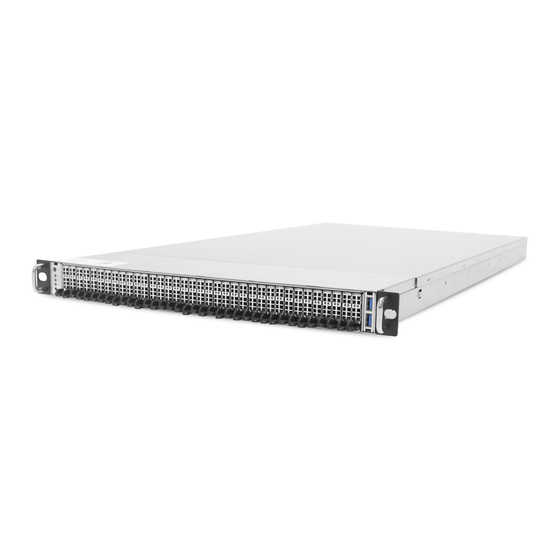
Chapter 1 Product Features 1�3 Features FB127-LX is a 1U Storage Server Barebone that is specifically designed to accomodate up to 36 front-serviceable NGSFF SSD bays and used for all flash servers. This Server barebone offers 5X the capacity relative to prior-generation U.2 devices. - Page 13 Chapter 1 Product Features • Major Components AC 1200W or 1600W 1+1 redundant hi-efficiency power supply 80+ 24 DIMM slots across 12 memory channels 7 x 40 x 56mm dual-rotor hot swap fan modules FB127-LX User's Manual...
-
Page 14: Chapter 2� Hardware Setup
2.1.1 Processor Support The server board includes two processor sockets (LGA3647) that supports up to two of the Intel® Xeon® Processor Scalable Family and provides a Thermal Design Power (TDP) of up to 165W on selected models. FB127-LX User's Manual... - Page 15 2.1.2 Processor Heat Sink Module and Processor Socket Assembly Each processor socket on the server board is pre-assembled with a loading mechanism that allows to secure the Processor Heat Sink Module (PHM) to the server board as shown below. FB127-LX User's Manual...
- Page 16 The PHM refers to the sub-assembly where the heat sink and processor are clipped together onto the server board prior installation. The PHM consists of the components as shown below. Processor Heat Sink Module (PHM) Sub-Assembly Processor Heatsink Module (PHM) FB127-LX User's Manual...
- Page 17 Failure t o tighten the heat sink screws i n the specified order may cause damage t o the processor socket assembly. Heat s ink screws should b e tightened t o 12 In-Lbs T orque o n indicated order on the top of the heat sink label. FB127-LX User's Manual...
-
Page 18: 2�2 System Memory
2�2 System Memory This server board supports up to twelve DDR4 2400/2666 Registered ECC SDRAM(RDIMM) / Load-Reduced DIMM (LRDIMM). CPU1 JDIMMJ1 JDIMMJ0 JDIMMK1 JDIMMK0 JDIMML1 JDIMML0 JDIMMC0 JDIMMC1 JDIMMB0 JDIMMB1 JDIMMA0 JDIMMA1 CPU0 JDIMMD1 JDIMMD0 JDIMME1 JDIMME0 JDIMMF1 JDIMMF0 FB127-LX User's Manual... - Page 19 JDIMMK0 JDIMMF1 JDIMML1 JDIMMF0 JDIMML0 CPU1 CPU0 JDIMMI1 JDIMMC1 JDIMMH1 JDIMMB1 JDIMM_I0 JDIMM_C0 JDIMMG1 JDIMMA1 JDIMM_H0 JDIMM_B0 8 DIMMs CPU1 CPU1 CPU0 CPU0 JDIMM_G0 JDIMM_A0 JDIMMD1 JDIMMJ1 JDIMMJ0 JDIMMD0 JDIMME1 JDIMMK1 JDIMME0 JDIMMK0 JDIMM_L0 JDIMM_F0 JDIMMF1 JDIMML1 FB127-LX User's Manual...
- Page 20 JDIMMK1 JDIMM_L0 JDIMM_F0 JDIMMF1 JDIMML1 CPU1 CPU0 JDIMM_I0 JDIMM_C0 JDIMM_I1 JDIMM_C1 JDIMM_H0 JDIMM_B0 JDIMM_H1 JDIMM_B1 18 DIMMs CPU1 CPU1 CPU0 CPU0 JDIMM_G0 JDIMM_A0 JDIMM_G1 JDIMM_A1 JDIMMJ1 JDIMMD1 JDIMM_J0 JDIMM_D0 JDIMME1 JDIMMK1 JDIMM_K0 JDIMM_E0 JDIMMF1 JDIMML1 JDIMM_L0 JDIMM_F0 FB127-LX User's Manual...
- Page 21 JDIMM_E0 JDIMM_L1 JDIMM_F1 JDIMM_L0 JDIMM_F0 CPU1 CPU0 JDIMM_I0 JDIMM_C0 JDIMM_I1 JDIMM_C1 JDIMM_H0 JDIMM_B0 JDIMM_H1 JDIMM_B1 JDIMM_G0 JDIMM_A0 24 DIMMs JDIMM_G1 JDIMM_A1 CPU1 CPU1 CPU0 CPU0 JDIMM_J1 JDIMM_D1 JDIMM_J0 JDIMM_D0 JDIMM_K1 JDIMM_E1 JDIMM_K0 JDIMM_E0 JDIMM_L1 JDIMM_F1 JDIMM_L0 JDIMM_F0 FB127-LX User's Manual...
- Page 22 2.2.2 DIMM Installation Procedure Unlock the DIMM socket by pressing the retaining clips outward. Insert module vertically and press down until the DImm snaps into place. Note: DIMM notch and socket bump must align as shown. DIMM notch FB127-LX User's Manual...
-
Page 23: 2�3 Removing And Installing Chassis Top Cover
2. Push the top cover vertically away from the front panel and pull upward to remove. 2.3.2 Installing the top cover of the chassis 1. Position the top cover onto the chassis. 2. Push the top cover vertically towards the front panel. FB127-LX User's Manual... -
Page 24: 2�4 Removing And Installing The Air Duct
Chapter 2 Hardware Setup 2�4 Removing and Installing the Air Duct 2.4.1 Removing the air duct Pull the air duct up and out of the chassis. 2.4.2 Installing the air duct Position the air duct into the enclosure. FB127-LX User's Manual... -
Page 25: 2�5 Removing And Installing The Power Supply Unit Module
1. Push the latch. 2. Hold the tray handle. 3. Pull the tray handle on the power supply module to remove. 2.5.2 Installing the power supply unit module 1. Push the tray handle on the power supply to install. FB127-LX User's Manual... -
Page 26: 2�6 Removing And Installing The Fan Module
Chapter 2 Hardware Setup 2�6 Removing and Installing the Fan Module 2.6.1 Removing the fan module Pull the fan module from the fan slot. 2.6.2 Installing the fan module Insert the fan module into the fan slot. FB127-LX User's Manual... -
Page 27: 2�7 Removing And Installing The Ocp Card/M�2 Card
2.7.3 Removing the M.2 card Pull the M.2 carefully to remove. 2.7.4 Installing the M.2 card Insert the carefully to install. Make certain to position the M.2 card in the correct slot. FB127-LX User's Manual... -
Page 28: 2�8 Removing And Installing The Pcie Card
2�8 Removing and Installing the PCIe Card 2.8.1 Removing the PCIe card Unscrew the screws x 2 pcs on the PCIe bracket to remove. 2.8.2 Installing the PCIe card Secure the screws x 2 pcs on the PCIe bracket to install. FB127-LX User's Manual... -
Page 29: 2�9 Removing And Installing The Ngsff Nvme Ssd
2.9.1 Removing the NGSFF NVMe SSD tray Press the tray lever upward and pull the tray out of the enclosure to remove. 2.9.2 Installing the hard disk drive tray Insert the tray into the enclosure to install. FB127-LX User's Manual... -
Page 30: 2�10 Tool-Less Blade Slide Installation
Chapter 2 Hardware Setup 2�10 Tool-less Blade Slide Installation 1. Pull on the ‘’Front-Release’’to unlock the inner channel from the Slide Assembly. 2. Release the Detent-Lock and push Middle Channel inwards to retract Middle Channel. FB127-LX User's Manual... - Page 31 Chapter 2 Hardware Setup Optional: Remove Metal Spacer for Aluminium Racks Metal Spacer 3. Aligning the Front Bracket with the Mounting Hole. 4. Push in to assembly the Front Bracket onto the Rack. FB127-LX User's Manual...
- Page 32 Chapter 2 Hardware Setup 5. Now the bracket is fixed onto the Rack. (Optional M6x10L screws are to secure the rails with posts if needed.) 6. Refer to Diagram 3. & 4. to assemble the End Bracket onto the Rack. FB127-LX User's Manual...
- Page 33 Chapter 2 Hardware Setup 7. Assemble the inner channel onto the chassis using thescrews provided. 8. Push the chassis with inner channels into Slide to complete Rack Installation. FB127-LX User's Manual...
-
Page 34: Chapter 3� Motherboard Settings
PCI Express x 16 Port3a(IOU2) Placement PCI Express x 16 Port2a(IOU1) PCI Express x 16 Port3a(IOU2) Port2a(IOU1) Port1a(IOU0) Port1a(IOU0) PCIEX48 Riser Slot CPU0 CPU1 CONN B PCI Express x 8 Port3c(IOU2) CONN C CONN A PCI Express x 8 Port3a(IOU2) FB127-LX User's Manual... -
Page 35: 3�2 Motherboard Placement
Chapter 3 Motherboard Settings 3�2 Motherboard Placement CPU0 CPU1 FB127-LX User's Manual... -
Page 36: 3�3 Motherboard Content List
JPMBUS FAN2B CONN SPI ROM Socket JSPI_BIOS FAN3A CONN BMC Reset JBMC_RST FAN3B CONN BMC Disable JBMC_DIS SAS IOC UART SAS IOC ACTIVITY BMC Buzzer JBUZZER System PG Lock JPG_LOCK SAS IOC ERROR LED SAS IOC ICE FB127-LX User's Manual... -
Page 37: 3�4 Internal Connectors/Jumpers
Chapter 3 Motherboard Settings 3�4 Internal Connectors/Jumpers Power Supply Connector Pin-out (JPWR6 / JPWR7) Power Supply Connector Pin-out (JPWR5) Power Supply Connector Pin-out (J9 / J10) SATA DOM Header definition (JDOM_PWR) +12V FB127-LX User's Manual... - Page 38 Chapter 3 Motherboard Settings Internal Connectors/Jumpers AUX Power Header definition (JPWR_AUX) AUX Power Header definition (JPWR1 / JPWR2 / JPWR3 / JPWR4) Front I/O USB Header definition (JUSB_INT1 / JUSB_INT2) Front I/O USB 2.0 Header definition (JUSB20) FB127-LX User's Manual...
- Page 39 Chapter 3 Motherboard Settings Internal Connectors/Jumpers SFF-8612 definition (JSYS_EXT) Front COM Header definition (JCOM1) FB127-LX User's Manual...
- Page 40 Chapter 3 Motherboard Settings Internal Connectors/Jumpers Front COM Header definition (JCOM4) Front VGA header definition (JVGA_INT) FB127-LX User's Manual...
- Page 41 Chapter 3 Motherboard Settings Internal Connectors/Jumpers BMC GPIO header definition (JBMC_GPIO1) BMC GPIO header definition (JBMC_GPIO2) Interposer header definition (JINTERPOSER) IPMB header definition (JBMC_I2C1) FB127-LX User's Manual...
- Page 42 Chapter 3 Motherboard Settings Internal Connectors/Jumpers BMC I2C header definition (JBMC_I2C10) Front Panel header definition (JFRNT_SSI) LCM header definition (JLCM) FB127-LX User's Manual...
- Page 43 Chapter 3 Motherboard Settings Internal Connectors/Jumpers PCH GPIO header definition (JPCH_GPIO) PCH GPIO header definition (JSGPIO) PCH GPIO header definition (JSSGPIO) Debug port header definition (JLPC_DP) Buzzer header definition (JBUZZER) FB127-LX User's Manual...
- Page 44 Chapter 3 Motherboard Settings Internal Connectors/Jumpers VROC KEY header definition (JRAID_KEY) PCIE Hot-Plug SMB header definition (JPCIE_HP) HFI header definition (JHFI1) FB127-LX User's Manual...
- Page 45 Chapter 3 Motherboard Settings Internal Connectors/Jumpers PCH GPIO header definition (JPCH_GPIO) VRM SMB header definition (JSMB_VR) Debug port header definition (JESPI) FAN 1 x 4 header definition (J4 / J21 / J22) +12V TACH FB127-LX User's Manual...
- Page 46 Internal Connectors/Jumpers FAN 1 x 6 header definition (J19 / J20 / J23 / J25 / J26 / J27 / J28) +12V TACH FAN_PRSNT_N LED_FAN_FAULT PMBus header definition (JPMBUS) SMB_PMBUS_CLK SMB_PMBUS_DATA PMBUS_ALERT_N +3.3V Power Supply header definition (JPMBUS_PDB) FB127-LX User's Manual...
- Page 47 Chapter 3 Motherboard Settings Internal Connectors/Jumpers NGFF Connector definition (JNGFF1 / JNGFF2) FB127-LX User's Manual...
- Page 48 Chapter 3 Motherboard Settings Internal Connectors/Jumpers FB127-LX User's Manual...
-
Page 49: 3�5 Leds
System power good is not ready Yellow Resume Well Reset ready RSMRST PGLED Resume Well Reset is not ready Blue UID activity detected UID LED No UID activity detected Blue (Blinking) NGFF activity detected NGFF LED No NGFF activity detected FB127-LX User's Manual... -
Page 50: Chapter 4. Bios Configuration Settings
INSTEAD OF POST MESSAGES. Press ESC to run the setup procedure. Choose the SCU to enter the Setup menu. Caution: For the official released version, the last digit of the BIOS Version must end in an "0." FB127-LX User's Manual... - Page 51 Chapter 4 BIOS Configuration Settings Identify the BIOS Version. Load Optimal Default setting. Save the setting and exit the BIOS setup utility. FB127-LX User's Manual...
-
Page 52: 4�1 Updating Bios
Chapter 4 BIOS Configuration Settings 4�1 Updating BIOS Important Notes: To identify the current BIOS version, please check out on BIOS setup. FB127-LX User's Manual... - Page 53 , H2offt-d.exe, and bin file in the same folder. Please follow the instructions to update whole flash part: Execute flash.bat to update Flash in the DOS environment. Reboot system. FB127-LX User's Manual...
-
Page 54: Chapter 5. Bmc Configuration Settings
BMC management port BMC management port (Dedicated NIC channel 1) (Share NIC channel 8) 5�1 Method 1 (Use the BIOS setup) 1. BIOS SETUP Advanced H2O IPMI configuration BMC configuration IPv4 source Static FB127-LX User's Manual... - Page 55 Chapter 5 BMC Configuration Settings FB127-LX User's Manual...
- Page 56 Chapter 5 BMC Configuration Settings 3. Type in the subnet mask address. 4. Type in the gateway address. FB127-LX User's Manual...
-
Page 57: 5�2 Method 2 (Use A Dos Tool - Syscheck)
5�2 Method 2 (Use a Dos tool - Syscheck) 1. Type in "sc –lanset." 2. Modify the IP setting. Note: type 1 for selecting static IP mode or type 2 for selecting DHCP mode. 3. Type in the IP address. FB127-LX User's Manual... - Page 58 The IP address below is an example using a default IP setting. The IP address is configurable. 5. Configure the gateway address to complete the BMC IP configuration. Note: Type sc.exe –langet command to obtain BMC IP and MAC address. FB127-LX User's Manual...
-
Page 59: 5�3 Connect To Bmc
: The default user name and password are in lower-case characters. note : Users who login with the root user name and password will have full administrative power. The root password can be changed after login. FB127-LX User's Manual... - Page 60 Chapter 5 BMC Configuration Settings 3. Dashboard: 4. Server Health - Sensor Readings: 5. Settings: FB127-LX User's Manual...
- Page 61 Chapter 5 BMC Configuration Settings Mouse Mode setting: • For Windows OS environment, set mode to absolute. • For Linux OS environment, set mode to relative. • For SLES-11 OS environment, set mode to other mode. 6. Remote Control: FB127-LX User's Manual...
- Page 62 Chapter 5 BMC Configuration Settings Launch KVM: Please refer to AIC BMC User Guide for more information on AIC BMC. FB127-LX User's Manual...
-
Page 63: 5�4 Updating Bmc Firmware
OB127C01 A:\ OB127C01>a.bat This is just an example. The latest BMC firmware version is available from the FAE or AIC website. 4. After updating the BMC firmware, please turn off and then turn on the system. Notes: 1. DO NOT USE EMM386 IN DOS ENVIRONMENT WHEN UPDATING FIRMWARE OR YOU WILL GET A FAIL. -
Page 64: Chapter 6� Technical Support
Chapter 1 Product Introduction Chapter 1 Product Introduction Chapter 6� Technical Support www�aicipc�com • TAIWAN Tel: +886 3 433 9188 Fax: +886 3 287 1818 Email: sales@aicipc�com�tw • CHINA Tel: +86�21�54961421, +86�21�54961422 Fax: Extension: 608 Email Technical Support: support@aicipc�com • AMERICA - West coast Tel: +1�909�895�8989 Fax: +1�909�895�8999 Email: sales@aicipc�com...
Need help?
Do you have a question about the FB127-LX and is the answer not in the manual?
Questions and answers