Table of Contents
Advertisement
Quick Links
Advertisement
Table of Contents

Subscribe to Our Youtube Channel
Related Manuals for AIC SB202-LB


Summary of Contents for AIC SB202-LB
- Page 1 SB202-LB Storage Server Barebone User's Manual UM_SB202-LB_v5.1_111918...
-
Page 2: Table Of Contents
Table of Contents Preface ������������������������������������������������������������������������������������������������� i Safety Instructions ������������������������������������������������������������������������������ ii About This Manual ������������������������������������������������������������������������������ iv Chapter 1� Product Features �������������������������������������������������������������� 1 1�1 Box Contents ������������������������������������������������������������������������������������1 1.2 Specifications������������������������������������������������������������������������������������2 1�3 Feature ����������������������������������������������������������������������������������������������3 Chapter 2� Hardware Setup ���������������������������������������������������������������� 6 2�1 Central Processing Unit (CPU) �����������������������������������������������������������6 2.1.1 Removing the processor ..................6 2.1.2 Installing the processor ..................8 2.1.3 CPU Heatsink .................... - Page 3 Chapter 3� Hardware Settings ���������������������������������������������������������� 38 3�1 Motherboard Block Diagram ������������������������������������������������������������38 3�2 Content List �������������������������������������������������������������������������������������39 3�3 Motherboard Layout ������������������������������������������������������������������������40 3�4 Connector and Jumper ��������������������������������������������������������������������41 3�5 System LEDs ����������������������������������������������������������������������������������49 3.5.1 Front Panel LED ....................49 3.5.2 Rear Panel LED ....................50 3.5.3 Internal LEDs ....................
- Page 4 4.4.5 USB Configuration ..................72 4.4.6 PCH Chipset Configuration ................72 4.4.7 Processor Configuration ................. 72 4.4.8 Advanced Power Management Configuration ..........73 4.4.9 Common RefCode Configuration ..............73 4.4.10 QPI Configuration ..................74 4.4.11 Memory Configuration .................. 75 4.4.12 IIO Configuration .................... 76 4.4.13 Console Redirection ..................
- Page 5 Copyright © 2015 AIC, Inc� All Rights Reserved� This document contains proprietary information about AIC products and is not to be disclosed or used except in accordance with applicable agreements.
- Page 6 Document Release History Release Date Version Update Content 2015 Release to public. August 1. Grammar error update 2018 1. Section 3.7 HDD backplane update November 2. Delete Chapter 6 2018 3. New cover...
-
Page 7: Preface
Disclaimer AIC shall not be liable for technical or editorial errors or omissions contained herein. The information provided is provided "as is" without warranty of any kind. To the extent permitted by law, neither AIC or its affiliates, subcontractors or suppliers will be liable for incidental, special or consequential damages including downtime cost;... -
Page 8: Safety Instructions
Safety Instructions Before getting started, please read the following important cautions: • All cautions and warnings on the equipment or in the manuals should be noted. • Most electronic components are sensitive to electrical static discharge. Therefore, be sure to ground yourself at all times when installing the internal components. •... - Page 9 • If the equipment is not used for a long time, disconnect the equipment from mains to avoid being damaged by transient over-voltage. • Never open the equipment. For safety reasons, only qualified service personnel should open the equipment. • If one of the following situations arise, the equipment should be checked by service personnel: 1.
-
Page 10: About This Manual
This document pellucidly presents a brief overview of the product design, device installation, and firmware settings for SB202-LB. For the latest version of this user's manual, please refer to the AIC website: http://www.aicipc.com/tw/productdetail/456. -
Page 11: Chapter 1� Product Features
SB202-LB User's Manual Chapter 1. Product Features SB202-LB User Manual SB202-LB is a high density storage server that includes mother board, chassis, power supply, and HDD backplane. For more information about our product, please visit our website at http://www.aicipc.com/en. Before removing the subsystem from the shipping carton, visually inspect the physical condition of the shipping carton. -
Page 12: 1.2 Specifications
SB202-LB User's Manual Chapter 1. Product Features 1.2 Specifications mm : 430 x 680 x 88.2 Dimensions (W x D x H) bracket area inches : 17 x 26.8 x 3.5 AIC Server Board Libra Rear I/O Motherboard 2 x USB 3.0 Type A... -
Page 13: 1�3 Feature
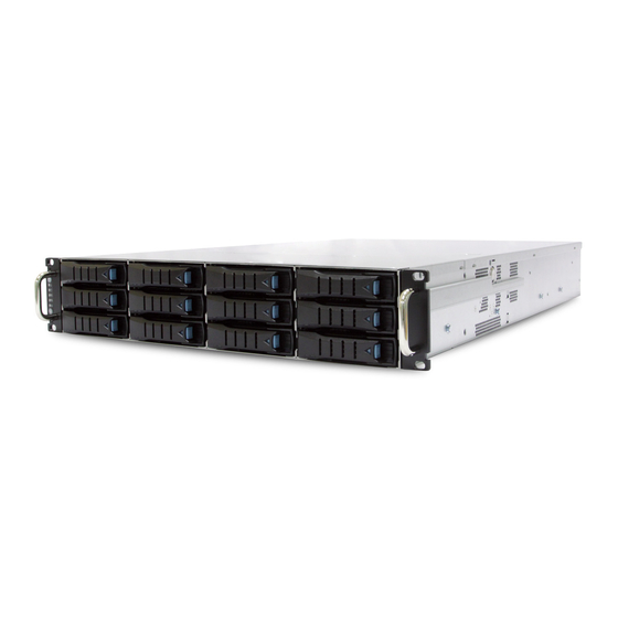
Chapter 1. Product Features 1�3 Feature SB202-LB is a reliable 2U storage server barebone with twelve 3.5” hotswap drive bays. This product is designed to accomodate the AIC-patented serverboard, Libra, which sup- ports two Intel® Xeon® Processors E5-2600 v3 and v4 processors and 16 DDR4 DIMM to offer greater perfomance, efficiency, and utility for our customers. - Page 14 SB202-LB User's Manual Chapter 1. Product Features Front Panel Power On/Off Button System Power LED System HDD Activity LED System LAN LED System Service ID Button Service ID Button System Reset Button Rear Panel 800W 1+1 redundant power supply 6 x PCIe 3.0 slots...
- Page 15 SB202-LB User's Manual Chapter 1. Product Features Major Components u 12 x 3.5" hotswap external HDD trays v 3 x 8038 mm fans w 800W 1+1 redundant PSU PMbus 1.2 80+ Gold x AIC Libra Server Board...
-
Page 16: Chapter 2� Hardware Setup
Chapter 2� Hardware Setup SB202-LB User's Manual Chapter 2 Hardware Setup 2�1 Central Processing Unit (CPU) 2�1�1 Removing the processor Step 1 Remove the heatsink. The heatsink is attached to the server board or -processor socket with captive fasteners. Use a #2 Phillips* screwdriver to loosen the screws x 4 located on the heatsink corners diagonally using the following procedure (1a) to (1b). - Page 17 SB202-LB User's Manual Chapter 2 Hardware Setup Step 2 Unlatch the CPU Load Plate by following procedures (2a) to (2b). (2a) Push the lever handle labeled “OPEN 1st” (see letter A) down and towards the CPU socket. Rotate the lever handle upward.
-
Page 18: Installing The Processor
SB202-LB User's Manual Chapter 2 Hardware Setup 2�1�2 Installing the processor CAUTION Processor must be appropriate: you may damage the server board if you install a processor that is inappropriate for your server. CAUTION ESD and handling processors: reduce the risk of electrostatic discharge (ESD) damage to the processor by doing the following: (1) Touch the metal chassis before touching the processor or server board. - Page 19 SB202-LB User's Manual Chapter 2 Hardware Setup Step 1 Remove the processor from its package by following procedures (1a) to (1b). (1a) Carefully remove the protective cover from the backside of the CPU. Take care not to touch any CPU contacts (see letter A).
- Page 20 SB202-LB User's Manual Chapter 2 Hardware Setup Step 2 Remove the socket cover from the load plate. NOTE The socket cover should be saved and re-used should the processor need to be removed at any time in the furture. Save the protective cover.
- Page 21 SB202-LB User's Manual Chapter 2 Hardware Setup Step 5 Installing the heatsink on top of the processor. NOTE The processor heatsink for CPU1 and CPU2 is different.. FXXCA91X91HS is for CPU1, while FXXEA91X91HS2 is for CPU2. Mislocating the heatsink will cause serious thermal damage.
-
Page 22: Cpu Heatsink
SB202-LB User's Manual Chapter 2 Hardware Setup 2�1�3 CPU Heatsink Carefully position heatsink over the CPU0 and CPU1, and align the heatsink screws with the screw holes in the motherboard. CAUTION Possible thermal damage may occur when moving the heatsink. Avoid moving the heatsink after it has contacted the top of the CPU. -
Page 23: 2�2 System Memory
SB202-LB User's Manual Chapter 2 Hardware Setup 2�2 System Memory This server board supports up to sixteen DDR4 1333/1600/1866/2133 Registered ECC SDRAM(RDIMM) / Load-Reduced DIMM (LRDIMM). JDIMMG0 JDIMMG1 JDIMMH0 JDIMMA0 JDIMMA1 JDIMMH1 JDIMMB0 JDIMMB1 JCPU1 JCPU0 JDIMMF1 JDIMMF0 JDIMME1 JDIMMD1... - Page 24 SB202-LB User's Manual Chapter 2 Hardware Setup 2�2�1 DIMM Installation Order Popoluate the DIMMs slots in the following order. JDIMMG0 JDIMMA0 JDIMMG1 JDIMMA1 JDIMMH0 JDIMMB0 JDIMMH1 JDIMMB1 DIMM Numbe rs DIMM A RRANGM ENT CPU1 CPU0 CPU1 CPU0 2 DIMMs...
- Page 25 SB202-LB User's Manual Chapter 2 Hardware Setup JDIMMG0 JDIMMA0 JDIMMG1 JDIMMA1 JDIMMH0 JDIMMB0 JDIMMH1 JDIMMB1 CPU1 CPU0 JDIMM_ G0 JDIMM_A0 JDIMM_ G1 JDIMM_A1 10 DIMMs CPU1 CPU0 JDIMM_ H0 JDIMM_B0 JDIMM_ F0 JDIMM_D0 JDIMM_ E0 JDIMM_C0 JDIMMF1 JDIMMD1 JDIMMF0 JDIMMD0...
-
Page 26: Dimm Installation
SB202-LB User's Manual Chapter 2 Hardware Setup 2�2�2 DIMM Installation Step 1 Unlock the DIMM socket by pressing the retaining clips outward. Step 2 Insert the memory module into the slot. Make sure that the DIMM notch is accurately positioned. -
Page 27: 2�3 Removing And Installing The Top Cover
SB202-LB User's Manual Chapter 2 Hardware Setup 2�3 Removing and Installing the Top Cover Push the release button on both sides and slide forward the top cover to open cover. -
Page 28: 2�4 Removing And Installing The Hard Disk Drive
SB202-LB User's Manual Chapter 2 Hardware Setup 2�4 Removing and Installing the Hard Disk Drive 2�4�1 Installing the Hard Disk Drive Place the HDD into tool-less HDD tray untli it snaps. Please check if the screw holes on the HDD match the dimples on HDD tray. -
Page 29: Installing The Hard Disk Drive Tray
SB202-LB User's Manual Chapter 2 Hardware Setup 2�4�2 Installing the Hard Disk Drive Tray Insert the drive tray into chassis HDD cage. Make sure the drive tray is correctly secured in place when its front edge aligns with the bay edge. Push the tray lever until... -
Page 30: 2�5 Removing And Installing The Fan Module
SB202-LB User's Manual Chapter 2 Hardware Setup 2�5 Removing and Installing the Fan Module 2�5�1 Removing the Fan Pull the fan module from the fan slot. -
Page 31: Installing The Fan
SB202-LB User's Manual Chapter 2 Hardware Setup Pull the fan module up gently and taking out the fan module by removing rubbers out from the fan bar. 2�5�2 Installing the Fan Make sure the 4 rubbers and connector insert firmly while fan module is inserted. -
Page 32: 2�6 Removing And Installing The Hdd Backplane Module
SB202-LB User's Manual Chapter 2 Hardware Setup 2�6 Removing and Installing the HDD Backplane Module 2�6�1 Removing the HDD Backplane Step 1 Unplug all connectors and HDDs from HDD backplane. Step 2 Release the lock pin. 2�6�2 Installing the HDD Backplane Step 1 Slide the HDD backplane module into the enclosure. -
Page 33: Installing The Hdd Backplane
SB202-LB User's Manual Chapter 2 Hardware Setup Step 3 Lift upward to remove. 2.6.3 Installing the HDD backplane module Step 1 Align the module with the hooks and insert it into the enclosure firmly. Step 2 Secure the module with the lock pin. -
Page 34: 2�7 Removing And Installing The Power Supply Unit Module
SB202-LB User's Manual Chapter 2 Hardware Setup 2�7 Removing and Installing the Power Supply Unit Module 2�7�1 Removing the Power Supply Unit Step 1 Remove power cable and loosen the thumb screw. Step 2 Push the latch and hold the tray handle. -
Page 35: 2�8 Removing And Installing The Pcie Card
SB202-LB User's Manual Chapter 2 Hardware Setup 2�8 Removing and Installing the PCIe Card Turn off your Storage Server Barebone and disconnect the power supply. 2�8�1 Installing the PCIe Card Step 1 Remove PCIe bracket slot cover. Step 2 Take the card and check for downside of the printedboard connectors. - Page 36 SB202-LB User's Manual Chapter 2 Hardware Setup 4. Locate the screws. Step 3 Insert the card gently by rolling in the side "right" between the edge of the motherboard and the wall of the enclosure. Step 4 Press the PCIe card firmly into the slot.
- Page 37 SB202-LB User's Manual Chapter 2 Hardware Setup Step 5 Check if your earthing is working properly . Step 6 Turn on your barebone. The system will automatically detect new hardware.
-
Page 38: 2�9 Removing And Installing The Rj45 Module
SB202-LB User's Manual Chapter 2 Hardware Setup 2�9 Removing and Installing the RJ45 Module Turn off your Storage Server Barebone and disconnect the power supply. 2�9�1 Installing the RJ45 Module Step 1 Remove the PCIe bracket slot cover. Step 2 Take the RJ45 module and insert onto the chassis. Be sure the RJ45... - Page 39 SB202-LB User's Manual Chapter 2 Hardware Setup • Type Step 1 Press out additional flashing on the I/O shield to make room for the RJ45 module. Step 2 Align the module to the top and botton of the I/O shield.
- Page 40 SB202-LB User's Manual Chapter 2 Hardware Setup 2.9.2 Configure the RJ45 function setting Insert one end of the cable into port LAN3 of the barebone. Insert the other end of the cable into the corresponding port LAN4 on site of the barebone.
- Page 41 SB202-LB User's Manual Chapter 2 Hardware Setup 2�10 Tool-less Blade Slide Installation Separate the tool-less slide rail 1. Pull the inner rail out of the outer rail until it is fully extended. Press the locking tab down to release the inner rail.
- Page 42 SB202-LB User's Manual Chapter 2 Hardware Setup 2. Place the inner rail firmly against the side of the chassis. Make sure that the hooks are straight and aligned with the holes in the inner rail. Screw Screw 3. Slide the inner rail forward until it clicks into the locked position.
- Page 43 SB202-LB User's Manual Chapter 2 Hardware Setup 4. Press the locking tab and push the middle rail back into the outer rail.
- Page 44 SB202-LB User's Manual Chapter 2 Hardware Setup 5. Hang the hooks of the rails on the rack holes and if necessary, secure with screws. Optional Screws...
- Page 45 SB202-LB User's Manual Chapter 2 Hardware Setup 6. Repeat step 5 to mount the four ends, extending the rails as necessary.
- Page 46 SB202-LB User's Manual Chapter 2 Hardware Setup 7. Pull the middle rail out of the front of the outer rail and make sure that the ball bearing shuttle is locked at the front of the middle rail. Ball Bearing Shuttle Align the inner rails with the middle rails and then push evenly on both sides of the chassis until it clicks into the fully extended position.
- Page 47 SB202-LB User's Manual Chapter 2 Hardware Setup 8. Depress the locking tabs on both sides of the chassis simultaneously and push the chassis all the way into the rear of the rack. Screw Screw If additional security is required, secure the chassis handles to the front of the rack with two screws (optional).
-
Page 48: Chapter 3� Hardware Settings
Chapter 3� Hardware Settings SB202-LB User's Manual Chapter 3 Hardware Settings This section describes the jumpers, internal connectors, and internal LEDs settings in the server barebone. 3�1 Motherboard Block Diagram... -
Page 49: 3�2 Content List
SB202-LB User's Manual Chapter 3 Hardware Settings 3�2 Content List Connector/Jumper/Header Location Connector/Jumper/Header Location Ethernet (Single LAN1, LAN2 Intruder JINTRUDER Port) Ethernet (Dual Port) RJ45 PMBUS JPMBUS USB Port (Dual Port ) USB3.0 SPI ROM Socket JSPI COM Port Speaker... -
Page 50: 3�3 Motherboard Layout
SB202-LB User's Manual Chapter 3 Hardware Settings 3�3 Motherboard Layout JDIMMG0 JPMBUS JPWR2 JDIMMG1 JDIMMH0 JDIMMA 0 JDIMMA 1 JDIMMH1 JDIMMB0 JPWR1 JDIMMB1 VG A RTL8201EL JVGA_INT RJ45& JCPU1 JCPU_XDP USB3.0 JCPU0 RJ45 (LAN2) RJ45 (LAN1) JDIMMF1 JDIMMF0 JDIMME1 JDIMMD1... -
Page 51: 3�4 Connector And Jumper
SB202-LB User's Manual Chapter 3 Hardware Settings 3�4 Connector and Jumper JDIMMG0 JDIMMG1 JDIMMH0 JDIMMA 0 JDIMMH1 JDIMMA 1 JDIMMB0 JDIMMB1 JDIMMD1 JDIMMD0 JCPU1 JDIMMC1 JDIMMC0 JCPU0 JPG_LOCK1 JDIMMF1 JDIMMF0 JDIMME1 JDIMMD1 JPWR3 JDOM_PWR JDIMME0 JDIMMD0 JDIMMC1 JDIMMC0 JPG_LOCK1 JBAT... - Page 52 SB202-LB User's Manual Chapter 3 Hardware Settings 15 JUSB_INT 49 a J19 52 b J17 49 b J20 52 c J18 PWM4 FAN7_TACH HM_TD7- +12V HM_TD7+ 53 a J11 53 b J12 53 c J13 53 d J14 53 e J15...
- Page 53 SB202-LB User's Manual Chapter 3 Hardware Settings JDIMMG0 JDIMMG1 JDIMMH0 JDIMMA 0 JDIMMA 1 JDIMMH1 JDIMMB0 JDIMMB1 JCPU1 JTPM JCPU0 JSGPIO JSSGPIO JDIMMF1 JDIMMF0 JCMOS JDIMME1 JDIMMD1 JNTB JDIMME0 JDIMMD0 JDIMMC1 JDIMMC0 JSPI I210 I217 JSPKR1 JTPM JBAT JSGPIO JSSGPIO...
- Page 54 SB202-LB User's Manual Chapter 3 Hardware Settings 40 JNTB 43 a JLAN1 43 b JLAN2 JNTB Setting Short Downstream port Open Upstream port (Default) 48 J10...
- Page 55 SB202-LB User's Manual Chapter 3 Hardware Settings 18 JLPC_DP JDIMMG0 JDIMMG1 JDIMMH0 JDIMMA 0 JDIMMA 1 JDIMMH1 JDIMMB0 JDIMMB1 JCPU1 JCPU0 JDIMMF1 JDIMMF0 JDIMME1 JDIMMD1 JDIMME0 JDIMMD0 JDIMMC1 JDIMMC0 JPCH_GPIO JLPC_DP CN 1 20 JBMC_DP JNGFF JBMC_DP JLCM JPCH_GPIO JLPC_DP...
- Page 56 SB202-LB User's Manual Chapter 3 Hardware Settings 47 J5 50 a CN1 50 b CN2 SFF-8643 CONN A1.NC C1.SIO1_SAS_DOUT A2.SIO1_SAS_CLK C2.GND A3.GND C3.GND A4.SAS_EXP_RX_P6 C4. SAS_EXP_TX_P6 A5. SAS_EXP_RX_N6 C5. SAS_EXP_TX_N6 A6.GND C6.GND A7. SAS_EXP_RX_P7 C7. SAS_EXP_TX_P7 A8. SAS_EXP_RX_N7 C8. SAS_EXP_TX_N7 A9.GND...
- Page 57 SB202-LB User's Manual Chapter 3 Hardware Settings 51 JNGFF 1. GND 2. VCC3_3_2 3. GND 4. VCC3_3_4 5. PERn3 6. NC 7. PERp3 8. NC 9. GND 10. DAS_DSS#(O)(OD) 11. PETn3 12. VCC3_3_12 13. PETp3 14. VCC3_3_14 15. GND 16. VCC3_3_16 17.
- Page 58 SB202-LB User's Manual Chapter 3 Hardware Settings 6 JPWR 1 JPWR JDIMMG0 JDIMMG1 JDIMMH0 JDIMMA 0 JDIMMA 1 JDIMMH1 +12V JDIMMB0 JPWR1 JDIMMB1 +12V RTL8201E L +12V JVGA_INT RJ45& JCPU1 +12V USB3. 0 JCPU0 RJ45 (LAN2) RJ45 (LAN1) 7 JPWR 2...
-
Page 59: 3�5 System Leds
SB202-LB User's Manual Chapter 3 Hardware Settings 3�5 System LEDs 3�5�1 Front Panel LED Green System is on. Power System is off. Yellow (Blinking) Disk activity detected. Hard Disk Drive No disk activity detected. LAN1 activity detected. Yellow (Blinking) LAN1 LAN1 is not active. -
Page 60: Rear Panel Led
SB202-LB User's Manual Chapter 3 Hardware Settings 3�5�2 Rear Panel LED Green (Blinking) LAN* activity detected. LAN* (Right) LAN* is not active. LAN cable is not connected. 100M: Green LAN* (Left) Status LED 10M/ No connection: Off Green (Blinking) LAN1 activity detected. -
Page 61: Internal Leds
SB202-LB User's Manual Chapter 3 Hardware Settings 3�5�3 Internal LEDs LED4 LED1 LED3 LED2 Heart Beat On (Blinking) BMC activity detected. (LED4) BMC is not active. SYS PG LED System power is ready. (LED2) System power is not ready. RSMRST PG LED Resume Well Reset is ready. -
Page 62: 3�6 Hdd Backplane: 12 Bay
SB202-LB User's Manual Chapter 3 Hardware Settings 3�6 HDD Backplane: 12 Bay 3�6�1 Placement PCBA Placement... - Page 63 SB202-LB User's Manual Chapter 3 Hardware Settings 3�6�2 Connector Location Connector Location JFAN1 JFAN2 JFAN3 JFAN3 JI2C3 JEXP2 JI2C4 JI2C0 JFAN4 SASHD3 SASHD3 JPMBUS JPMBUS JEXP_UART JEXP_UART JPWR1 JPWR1 SASHD2 SASHD2 JMCU_DBG JMCU_DBG JPWR2 JPWR2 JMCU_UART JMCU_UART SASHD1 SASHD1 JFRONT...
- Page 64 SB202-LB User's Manual Chapter 3 Hardware Settings 3�6�3 Connectors Power Connector – JPWR1 Description Description +12V +12V +3.3V MUTE_L +5VSTBY PSU_N1 PS_ON_L Power Connector – JPWR2 Description Description +12V +12V +12V +12V PMBUS Connector – JPMBUS Description PMBUS_CLOCK PMBUS_DATA...
- Page 65 SB202-LB User's Manual Chapter 3 Hardware Settings I2C Connector – JI2C0, JI2C3, JI2C4 Description I2C_CLOCK I2C_DATA FAN Connector – JFAN1, JFAN2, JFAN3, JFAN4 Description +12V TACH Console for Expander – JEXP_UART Description Description DEBUG_RXD SMART_RXD +12V DEBUG_TXD SMART_TXD Remote Power Control – JMCU_UART...
- Page 66 SB202-LB User's Manual Chapter 3 Hardware Settings Console for MCU – JMCU_DBG Description MCU_RXD MCU_TXD 2.54mm Header for Front I/O – JFRONT • Fan number select Pin[5,6] Pin [3,4] Pin [1,2] Fan no� support Active Fan Locate Close Close Close...
- Page 67 SB202-LB User's Manual Chapter 3 Hardware Settings • Mute SW Description Remark MUTE Input(-) Active Low • Power/ID LED Description Remark For External LED(+) LED Anode For External LED(-) LED Cathode • Power SW Description Remark Power SW Input(-) Active Low •...
- Page 68 SB202-LB User's Manual Chapter 3 Hardware Settings 3�6�4 LEDs LED1 LED1 LED2 LED2 SASHD Status LED SASHD Status LED LED5 LED5...
- Page 69 SB202-LB User's Manual Chapter 3 Hardware Settings Blue (On) HDD present HDD Activity LEDs Blue (Blinking) HDD Activity detected or Locate HDD(slow) HDD no connect or Power Off No control bit is set or set by any of the following bits: 1.
- Page 70 SB202-LB User's Manual Chapter 3 Hardware Settings 3�6�5 Jumpers JMCU_RST JMCU_RST JMD_SEL JMD_SEL Open Normal, default JMCU_RST Close Reset MCU Open Normal, default JMD_SEL Close Boot loader mode...
-
Page 71: Drive Slot Map
SB202-LB User's Manual Chapter 3 Hardware Settings 3�6�6 Drive Slot Map... -
Page 72: 3�7 Hdd Backplane: 2 Bay
SB202-LB User's Manual Chapter 3 Hardware Settings 3�7 HDD Backplane: 2 Bay 3�7�1 Placement Top view Bottom view... -
Page 73: Connector Location
SB202-LB User's Manual Chapter 3 Hardware Settings 3�7�2 Connector Location Top view HDD0 HDD0 HDD1 Bottom view SATA1 SATA0 JPWR JLED_E HD_ACT_SW HD_ACT_SW 3�7�3 Connector BP Power (JPWR) Activity Selection (HD_ACT_SW0/HD_ACT_SW1) HDDIN0 SASIN0 Open: Standard. 1. On : And 5Hz on DAS, for SSD320. -
Page 74: Led Indicator
SB202-LB User's Manual Chapter 3 Hardware Settings 3�7�4 LED Indicator LED0 LED0 LED1 LED1 Blue (On) Link up Blue (Blinking) Activity detected SATA HD Link Blue (Off) Link down Status(LED0,LED1) Red (On) HDD error (external control only) Red (Off) HDD Normal... -
Page 75: Chapter 4. Bios Configuration Settings
Chapter 4. BIOS Configuration Settings SB202-LB User's Manual Chapter 4 BIOS Configuration Settings This chapter demonstrates how to configure the UEFI BIOS settings in your system device. You can enter the BIOS screen during system startup. To enter BIOS configuration settings, •... -
Page 76: 4�2 Bios Setup
SB202-LB User's Manual Chapter 4 BIOS Configuration Settings 4�2 BIOS Setup 4�2�1 BIOS Menu Press and to select the options of the menu bar. Press Enter to access the option screen. Menu Description Displays system information such as CPU bus speed, system... - Page 77 SB202-LB User's Manual Chapter 4 BIOS Configuration Settings Step 4 Load Optimal Default setting. Step 5 Save the setting and exit the BIOS setup utility.
-
Page 78: Bios Update
SB202-LB User's Manual Chapter 4 BIOS Configuration Settings 4�2�3 BIOS Update To identify the current BIOS version, please check the BIOS setup. - Page 79 SB202-LB User's Manual Chapter 4 BIOS Configuration Settings Update BIOS by INSYDE H2OFFT-D utility under DOS environment If you need to update Flash in the DOS environment, please use H2OFFT-D utility. To use this utility, you must include the flash.bat , H2OFFT-D.exe, and bin file in the same folder.
-
Page 80: 4�3 Main
SB202-LB User's Manual Chapter 4 BIOS Configuration Settings 4�3 Main Main Option Key: 4�3�1 Main Option Key Description Language Configures the language used for your BIOS settings. System time Configures the current time. System date Configures the current date. -
Page 81: 4�4 Advanced
SB202-LB User's Manual Chapter 4 BIOS Configuration Settings 4�4 Advanced Advanced Option Key: 4.4.1 Peripheral Configuration Configure periperhal devices. Peripheral Configuration Serial Port A Auto Enable Disable Serial Port B Serial Port C Auto Enable Disable Base I/O Address Interrupt... -
Page 82: Pch Sata Configuration
SB202-LB User's Manual Chapter 4 BIOS Configuration Settings 4.4.2 PCH SATA Configuration Select the SATA controller and hard disk drive type installed in your system. PCH SATA Configuration SATA Controller Enable Disable HDC Configure As AHCI RAID SATA Speed 1.0 Gb/s 3.0 Gb/s... -
Page 83: Usb Configuration
SB202-LB User's Manual Chapter 4 BIOS Configuration Settings 4.4.5 USB Configuration Configure the USB support USB Configuration USB BIOS Support Enable Disable UEFI Only XHCI Pre-Boot Enable Disable Driver XHCI Enable Disable Auto Smart Auto XHCI Streams Enable Disable EHCI 1... -
Page 84: 4.4.8 Advanced Power Management Configuration
SB202-LB User's Manual Chapter 4 BIOS Configuration Settings 4.4.8 Advanced Power Management Configuration Displays and provides option to change Power Management Settings. Advanced Power Management Configuration EIST (GV3) Enable Disable Config TDP Enable Disable IOTG Setting Enable Disable Uncore CLR Freq... -
Page 85: 4.4.10 Qpi Configuration
SB202-LB User's Manual Chapter 4 BIOS Configuration Settings 4.4.10 QPI Configuration Displays and provides option to change the QPI Settings. QPI Configuration Link Speed Mode Slow Fast Link Frequency Auto 6.4GT/s 8.0GT/s 9.6GT/s Auto Select Limited QPI General Legacy VGA... -
Page 86: 4.4.11 Memory Configuration
SB202-LB User's Manual Chapter 4 BIOS Configuration Settings MMIOL Resources Min=0, Max=8 Allocation Ratio Disable Ports and IIO without memory hotplug IIO Disable Disable Ports Only with memory hotplug QPI Per Socket CPU 0/ CPU1 Configuration Socket IO Min=0x0, Max=0x10... -
Page 87: 4.4.12 Iio Configuration
SB202-LB User's Manual Chapter 4 BIOS Configuration Settings RMT On Cold Fast Auto Enable Disable Boot BDAT Enable Disable ADR Mode Enable Disable Memory Topology Set Throttling Disable OLTT CLTT Mode DIMM Temp Stat Min=0,Max=255 Memory Thermal Auto Phase Enable... - Page 88 SB202-LB User's Manual Chapter 4 BIOS Configuration Settings Auto PCI-E Port Enable Socket 0 Disable PcieD01F0 - Port PCI-E Port Enable Disable Link Socket 0 PcieD01F1 - Port Auto Gen 1 (2.5 GT/s) Socket 0 Link Speed Gen 2 (5 GT/s)
-
Page 89: Console Redirection
SB202-LB User's Manual Chapter 4 BIOS Configuration Settings 4�4�13 Console Redirection Displays and provides Console Redirection Settings. Console Redirection Console Serial Enable Disable Redirect 4�4�14 System Event Log Press Enter to view or change the event log configuration. System Event Log... -
Page 90: Oemboard Function
SB202-LB User's Manual Chapter 4 BIOS Configuration Settings BMC Warmup Time Min=0, Max=240 Boot Option Enable Disable Support Wait For BMC Enable Disable Virtual Device Watchdog Timer Enable Disable Support Watchdog Timer Min=0, Max=240 Timeout No Action Power Down Hard... -
Page 91: 4�5 Security
SB202-LB User's Manual Chapter 4 BIOS Configuration Settings 4�5 Security Security Option Key: 4�5�1 Set Supervisor password Set Supervisor Password: Install or change the password and the length of the password must be greater than one character. Set Supervisor password... -
Page 92: 4�6 Power
SB202-LB User's Manual Chapter 4 BIOS Configuration Settings 4�6 Power Power Option Key: 4�6�1 Power Wake on PME: Determines the action taken when the system power is off and the PCI Power Management Enable wake up event occurs. Auto Wake on S5: Auto Wake on S5, By Day of Month or Fixed time of every day. -
Page 93: 4�7 Boot
SB202-LB User's Manual Chapter 4 BIOS Configuration Settings 4�7 Boot Boot Option Key: 4�7�1 Boot Boot Type: Select boot type to Dual type, Legacy type or UEFI type. Quick Boot: Allows InsydeH20 to skip certain tests while booting. This will decrease the time to boot the system. -
Page 94: Boot
SB202-LB User's Manual Chapter 4 BIOS Configuration Settings Boot Boot Type Dual Boot Type Legacy Boot Type UEFI Boot Type Quick Boot Enable Disable Quiet Boot Enable Disable Network Stack Enable Disable PXE Boot Enable Disable Capability USB Boot Enable... -
Page 95: Chapter 5. Bmc Configuration Settings
Chapter 5. BMC Configuration Settings SB202-LB User's Manual Chapter 5 BMC Configuration Settings Insert Ethernet LAN cable into the BMC LAN port. There are two methods to setup BMC IP: BMC management port 5�1 Method 1 (Use the BIOS Setup) Step 1 BIOS SETUPServer MgmtBMC network configuration... - Page 96 SB202-LB User's Manual Chapter 5 BMC Configuration Settings Step 2 Input the IP address. Set static IP.
- Page 97 SB202-LB User's Manual Chapter 5 BMC Configuration Settings Step 3 Input the subnet mask address.
-
Page 98: 5�2 Method 2 (Use A Dos Tool - Syscheck)
SB202-LB User's Manual Chapter 5 BMC Configuration Settings 5�2 Method 2 (Use a Dos Tool - Syscheck) Step 1 Type in "sc –lanset." Step 2 Modify the IP setting. NOTE Type 1 for selecting static IP Mode and type 2 for selecting DHCP Mode. -
Page 99: 5�3 Connect To Bmc
SB202-LB User's Manual Chapter 5 BMC Configuration Settings 5�3 Connect to BMC NOTE This feature works with JAVA 6 Runtime installed Console Environment. The IP address below is an example using default IP setting. Users are allowed to change the IP address for individual purposes Step 1 Open the browser then type default BMC IP address: 192.168.22.22... -
Page 100: Dashboard
SB202-LB User's Manual Chapter 5 BMC Configuration Settings 5�4 Web UI 5�4�1 Dashboard The Dashboard page gives the overall information about the status of a device. To open the Dashboard page, click Dashboard from the menu bar. A sample screenshot... -
Page 101: Field Replaceable Unit(Fru)
SB202-LB User's Manual Chapter 5 BMC Configuration Settings 5�4�2 Field Replaceable Unit(FRU) The FRU Information Page displays the BMC FRU file information. The information displayed in this page is Basic Information, Common Header Information, Chassis Information, Board Information and Product Information of the FRU device. -
Page 102: Server Health
SB202-LB User's Manual Chapter 5 BMC Configuration Settings 5�4�3 Server Health Sensor Readings All sensor related information will be displayed here. Double click on a record to toggle (ON / OFF) the live widget for that particular sensor. Event Log Events generated by the system will be logged here. -
Page 103: 5.4.4 Configuration
SB202-LB User's Manual Chapter 5 BMC Configuration Settings 5.4.4 Configuration Active Directory Settings The 'Active Directory' is currently disabled. To enable Active Directory and configure its settings. Click on 'Advanced Settings' button. DNS Server Settings Manage DNS settings of the device. - Page 104 SB202-LB User's Manual Chapter 5 BMC Configuration Settings Mouse Mode Settings Redirection console mouse mode settings can be modified here. NCSI Settings The following options are for configuring the channel number and package ID information for the NCSI interface. Network Settings...
- Page 105 SB202-LB User's Manual Chapter 5 BMC Configuration Settings Network Link Configuration Manage network link settings of the device. PAM Ordering This page is used to configure the PAM Ordering for the user authentication. PEF Management Use this page to configure Event Filter, Alert Policy and LAN Destination.
- Page 106 SB202-LB User's Manual Chapter 5 BMC Configuration Settings SMTP Settings Manage SMTP settings of the device. SSL Certificate Configuration This page is used to configure SSL certificate into the BMC. Using this, the device can be accessed in a secured mode. Upload SSL option is used to upload the certificate and private key file into the BMC.
-
Page 107: Remote Control
SB202-LB User's Manual Chapter 5 BMC Configuration Settings 5�4�5 Remote Control Console Redirection Press the button to launch the redirection console and manage the server remotely. Power Control and Status The current server power status is shown below. To perform a power control operation, select one of the options below and press "Perform Action."... - Page 108 SB202-LB User's Manual Chapter 5 BMC Configuration Settings Environmental setting: Press “ALT+C” for local and remote OS mouse control switching.
-
Page 109: Auto Video Recording
SB202-LB User's Manual Chapter 5 BMC Configuration Settings 5�4�6 Auto Video Recording Triggers Configuration This page allows the user to configure the events that will trigger the auto video recording function of the KVM server. Video Recording This page shows a list of available recorded video files on the BMC. Select a video and click the "Play Video"... -
Page 110: Maintenance
SB202-LB User's Manual Chapter 5 BMC Configuration Settings 5�4�7 Maintenance Preserve Configuration This page allows you to select the specific configuration items to be preserved in the cases of "Restore Configuration," and "Firmware Update without Preserve Configuration option." Restore Configuration This page allows you to restore the default configuration for your device. - Page 111 SB202-LB User's Manual Chapter 5 BMC Configuration Settings 5�4�8 Firmware Update Firmware Update Upgrade firmware of the device. Press "Enter Update Mode" to put the device in update mode. Image Transfer Protocol The following option allows you to configure firmware image protocol information.
-
Page 112: 5�5 Updating Bmc Firmware
SB202-LB User's Manual Chapter 5 BMC Configuration Settings 5�5 Updating BMC Firmware Step 1 Boot to the DOS (MS-DOS or Free DOS is workable). Step 2 Enter BMC firmware directory [XXXXXZYY]; XXXXX: project name; YY: firmware version; Z: Identify character, C for official, B for Beta. -
Page 113: Chapter 6� Technical Support
Chapter 6� Technical Support Taiwain, Global Headquarters South California, United States Address: No� 152, Section 4, Address: 21808 Garcia Lane Linghang N� Rd, Dayuan District, City of Industry, CA 91789, Taoyuan City 337, Taiwan United States Tel: +886-3-433-9188 Toll free: +7-4997019998 Fax: +886-3-287-1818 Tel: +1-909-895-8989 Sales Email: sales@aicipc�com�tw...
Need help?
Do you have a question about the SB202-LB and is the answer not in the manual?
Questions and answers