Table of Contents
Advertisement
Quick Links
Advertisement
Table of Contents

Subscribe to Our Youtube Channel
Related Manuals for AIC SB201-LB


Summary of Contents for AIC SB201-LB
- Page 1 SB201-LB Storage Server Barebone User's Manual UM_SB201-LB_v3_062718...
-
Page 2: Table Of Contents
CONTENTS PREFACE ������������������������������������������������������������������������������������������� i SAFETY INSTRUCTIONS �������������������������������������������������������������������� ii CHAPTER OVERVIEW ��������������������������������������������������������������������� iv Chapter 1� Product Features ������������������������������������������������������� 1 1�1 Box Content ����������������������������������������������������������������������������������������1 1.2 Specifications �������������������������������������������������������������������������������������2 1�3 Features �����������������������������������������������������������������������������������������������3 1�4 Four option SKUs ���������������������������������������������������������������������������������6 Chapter 2� Hardware Setup ������������������������������������������������������ 10 2�1 Central Processing Unit (CPU) ���������������������������������������������������������10 2�2 System Memory ��������������������������������������������������������������������������������17 2�3 Removing and Installing Top Cover �����������������������������������������������21 2�4 Removing and Installing the Hard Disk Drive ��������������������������������22... - Page 3 Copyright © 2016 AIC, Inc� All Rights Reserved� This document contains proprietary information about AIC products and is not to be disclosed or used except in accordance with applicable agreements.
-
Page 4: Preface
• Disclaimer AIC shall not be liable for technical or editorial errors or omissions contained herein. The information provided is provided "as is" without warranty of any kind. To the extent permitted by law, neither AIC or its affiliates, subcontractors or suppliers will be liable for incidental, special or consequential damages including downtime cost;... -
Page 5: Safety Instructions
SAFETY INSTRUCTIONS Before getting started, please read the following important cautions: • All cautions and warnings on the equipment or in the manuals should be noted. • Most electronic components are sensitive to electrical static discharge. Therefore, be sure to ground yourself at all times when installing the internal components. •... - Page 6 • If the equipment is not used for a long time, disconnect the equipment from mains to avoid being damaged by transient over-voltage. • Never open the equipment. For safety reasons, only qualified service personnel should open the equipment. • If one of the following situations arise, the equipment should be checked by service personnel: 1.
-
Page 7: Chapter Overview
Chapter 7 Technical Support For more information or suggestion, please verify and contact the nearest AIC corporation representative in your district or visit the AIC website. It is our pleasure to provide the best service for our customers. SB201-LB User's Manual... -
Page 8: Chapter 1� Product Features
• Enclosure( Power supply, fan, 24 x 2.5'' at front + 2 x 2.5" at internal/rear HDD tray included) • 2.5" HDD Tray • Power cord • Screws kit x 1set • (Include console serial cable) • Slide rail x 1set ♦ PACKAGE CONTENT MAY VARY PER REGION. SB201-LB User's Manual... -
Page 9: 1.2 Specifications
(W x D x H) inches : 17 x 25.4 x 3. 5 Rear I/O 2 x USB 3.0 Type A Motherboard AIC Server Board Libr a 1 x DB-15 Processor Support product family 1 x DB-9 Serial Port... -
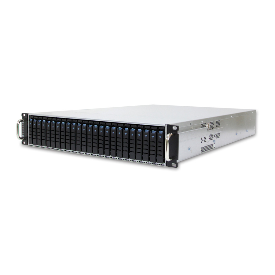
Page 10: 1�3 Features
Chapter 1 Product Features 1�3 Features SB201-LB is a reliable 2U storage server barebone with twenty-four 2.5” hotswap drive bays at front with two 2.5” hotswap drive bays at rear/internal. This product is designed to accomodate the AIC-patented serverboard, Libra, which supports two Intel®... - Page 11 Front Panel 1 x USB 3.0 port 24 x 2.5'' hot swap drive bays Rear Panel 2 x 2.5'' External hot swap drive bays (Option) AC 800W 1+1 redundant 6 x PCIe 3.0 slots(low-profile) high-efficiency power supply 80+ SB201-LB User's Manual...
- Page 12 Chapter 1 Product Features Top View 24 x 2.5” hot swap drive bays 3 x 80x38mm easy swap fans 3 x 80x38mm easy swap fans SB201-LB User's Manual...
-
Page 13: 1�4 Four Option Skus
Chapter 1 Product Features 1�4 Four option SKUs 1.4.1 12G Expander Backplane + rear hot swap O/S tray • 2U 24 bay Expander on Backplane. • 1U AC 750W/redundant power supply. • 2.5" x 2 External hot swap drive bays. SB201-LB User's Manual... - Page 14 Chapter 1 Product Features 1.4.2 12G Expander Backplane + internal O/S tray • 2U 24 bay Expander on Backplane. • 2U AC 800W 1+1 redundant high-efficiency power supply 80+. • 2.5" x 2 internal Drive Bracket. SB201-LB User's Manual...
- Page 15 Chapter 1 Product Features 1.4.3 12G Passive Backplane + rear hot swap O/S tray • 2U 24 bay Passive Expander on Backplane. • 750W/redundant power supply • 2.5" x 2 External hot swap drive bays SB201-LB User's Manual...
- Page 16 Chapter 1 Product Features 1.4.4 12G Passive Backplane + internal O/S tray • 2U 24 bay Passive Expander on Backplane. • AC 800W 1+1 redundant high-efficiency power supply 80+. • 2.5" x 2 internal Drive Bracket. SB201-LB User's Manual...
-
Page 17: Chapter 2� Hardware Setup
(1b) Proceed to screw 2 and loosen it by giving it two rotations and stop (see letter B). Similarly, loosen screws 3 and 4. Repeat steps A and B by giving each screw two rotations each time until all the screws are loosened. (1c) Lift the heatsink upward (see letter C). SB201-LB User's Manual... - Page 18 Remove the processor by carefully lifting it out of the socket, taking care NOT to drop the processor and not touching any pins inside the socket. Install the socket cover if a replacement processor is not going to be installed. SB201-LB User's Manual...
- Page 19 (1) Touch the metal chassis before touching the processor or server board. Keep part of your body in contact with the metal chassis to dissipate the static charge while handling the processor. (2) Avoid moving around unnecessarily. SB201-LB User's Manual...
- Page 20 The processor must align correctly with the socket opening before installation. DO NOT DROP the processor into the socket. NOTE : When possible, a CPU insertion tool should be used when installing the CPU. SB201-LB User's Manual...
- Page 21 Make sure the load plate tab engages under the socket lever when fully closed. (4b) Repeat the steps to latch the locking lever on the other side (see letter C). Latch the levers in the order as demonstrated. SB201-LB User's Manual...
- Page 22 (see letter D). Similarly, engage screws 3 and 4. (5c-3) Repeat steps C and D by giving each screw two rotations each time until each screw is lightly tightened up to a maximum of 8 inch-lbs torque (see letter E). CAUTION: Do not over-tighten fasteners. SB201-LB User's Manual...
- Page 23 Caution - Possible thermal damage. Avoid moving the heatsink after it has contacted the top of the CPU. Too much movement could disturb the layer of thermal compound, causing voids, and leading to ineffective heat dissipation and component damage. SB201-LB User's Manual...
-
Page 24: 2�2 System Memory
JDIMMD1 JDIMME0 JDIMMD0 JDIMMC1 JDIMMC0 JBMC_DP note : Slot 1 / Slot 3 Available ONLY When JCPU0 processor is installed. Slot 2 / Slot 4 / Slot 5 /Slot 6 Available ONLY When JCPU1 processor is installed. SB201-LB User's Manual... - Page 25 JDIMMD1 JDIMMF0 JDIMMD0 JDIMME1 JDIMMC1 JDIMMC0 JDIMME0 JDIMMG0 JDIMMA0 JDIMMG1 JDIMMA1 JDIMMB0 JDIMMH0 JDIMMB1 JDIMMH1 CPU1 CPU0 JDIMM_G0 JDIMM_A0 8 DIMMs JDIMM_H0 JDIMM_B0 CPU0 CPU1 JDIMM_F0 JDIMM_D0 JDIMM_E0 JDIMM_C0 JDIMMF1 JDIMMD1 JDIMMF0 JDIMMD0 JDIMME1 JDIMMC1 JDIMME0 JDIMMC0 SB201-LB User's Manual...
- Page 26 JDIMMA0 CPU1 CPU0 JDIMMG1 JDIMMA1 JDIMMH0 JDIMMB0 JDIMM_G0 JDIMM_A0 JDIMMH1 JDIMMB1 JDIMM_G1 JDIMM_A1 JDIMM_H0 JDIMM_B0 16 DIMMs JDIMM_H1 JDIMM_B1 CPU0 CPU1 JDIMM_F1 JDIMM_D1 JDIMM_F0 JDIMM_D0 JDIMM_E1 JDIMM_C1 JDIMMF1 JDIMMD1 JDIMMF0 JDIMMD0 JDIMM_E0 JDIMM_C0 JDIMME1 JDIMMC1 JDIMME0 JDIMMC0 SB201-LB User's Manual...
- Page 27 2.2.2 DIMM Installation Procedure Unlock a DIMM socket by pressing the retaining clips outward. Insert module vertically and press down until it snaps into place. Note: DIMM notch and socket bump must align as shown. DIMM notch SB201-LB User's Manual...
-
Page 28: 2�3 Removing And Installing Top Cover
Chapter 2 Hardware Setup 2�3 Removing and Installing Top Cover Push the release button on both sides of the cover and slide forward the top cover to open cover. SB201-LB User's Manual... -
Page 29: 2�4 Removing And Installing The Hard Disk Drive
Place the HDD into tool-less HDD tray untli it snaps. Please check if the screw holes on HDD match the dimples on HDD tray. The HDD can also be screwed on HDD tray by fastening two screws. SB201-LB User's Manual... - Page 30 Chapter 2 Hardware Setup 2.4.2 Insert the drive tray into chassis HDD cage. Make sure the drive tray is correctly secured in place. Push the tray lever until it reaches the end and clicks. SB201-LB User's Manual...
-
Page 31: 2�5 Removing And Installing The Fan Module
Chapter 2 Hardware Setup 2�5 Removing and Installing the Fan Module 2.5.1 Removing the fan module Pull to remove the fan module from the fan slot. AIRFLOW AIRFLOW AIRFLOW AIRFLOW SB201-LB User's Manual... - Page 32 Chapter 2 Hardware Setup Pull the fan module up gently. Remove the fan module by removing rubbers out from the fan bar. 2.5.2 Installing the fan module Make sure the 4 rubbers and connector insert firmly into the enclosure. SB201-LB User's Manual...
-
Page 33: 2�6 Removing And Installing The Hdd Backplane Module
Chapter 2 Hardware Setup 2�6 Removing and Installing the HDD Backplane Module 2.6.1 Removing the HDD backplane module Step 1 Unplug all the connectors and HDDs from HDD backplane. Step 2 Release the lock pin. SB201-LB User's Manual... - Page 34 Step 3 Loosen the screws x 9pcs on the backplane module. Step 4 Remove the backplane module. 2.6.2 Installing the HDD backplane module Step 1 Align the backplane with the hooks and insert it into the enclosure. Step 2 Secure the module with screws. SB201-LB User's Manual...
-
Page 35: 2�7 Removing And Installing The Power Supply Unit Module
Step 2 Push the latch and hold the tray handle. Step 3 Pull the tray handle out gently to slide the module out of the enclosure. 2.7.2 Installing the power supply unit module Push the module into the enclosure. SB201-LB User's Manual... -
Page 36: 2�8 Removing And Installing The Pcie Card
Step 2 Take the card and check for downside printedbord connectors. Keep the connector side downward. Locate the below positions: 1. Locate the external (connector) side of card. 2. Locate to fix right downside of the card. 3. Locate the PCI Slot to place the card printedbord connectors. SB201-LB User's Manual... - Page 37 (3a) Insert the card gently rolling in the side "right" between the edge of the motherboard and the wall of the Storage Server Barbone. (3b) Press firmly to completely plug the card into the PCI slot and the screws in Storage Server Barbone. SB201-LB User's Manual...
- Page 38 Chapter 2 Hardware Setup Step 4 Check if your earthing is working properly . Step 5 Turn on your Storage Server Barbone. The system will detect new hardware. SB201-LB User's Manual...
-
Page 39: 2�9 Removing And Installing The Rj45 Module
Turn off your Storage Server Barebone and disconnect the power supply. 2.9.1 Installing the RJ45 Module Step 1 Remove PCI Bracket Slot Cover. Step 2 Take the RJ45 module insert onto the chassis. Step 3 Make sure the RJ45 module is inserted to chassis properly. SB201-LB User's Manual... - Page 40 1. Punch out additional flashing on the I/O shield to make room for RJ45 module. 2. Align the module to the top and botton of the I/O shield for correct direction. 3. Secure the RJ45 module on the I/O shield using the screws. SB201-LB User's Manual...
- Page 41 2.9.2 Configure the RJ45 function setting Insert one end of the cable into port LAN3 of the barebone. Insert the other end of the LAN4 cable into the corresponding port on site of the barebone. 1. Type 2. Type SB201-LB User's Manual SB201-LB User's Manual...
-
Page 42: 2�10 Tool-Less Blade Slide Installation
Chapter 2 Hardware Setup 2�10 Tool-less Blade Slide Installation 2.10.1 Release and detach the inner rail from the slide. PUSH SB201-LB User's Manual... - Page 43 Chapter 2 Hardware Setup 2.10.2 Attach the inner rail to the system. Click! SB201-LB User's Manual...
- Page 44 Chapter 2 Hardware Setup 2.10.3 Attach the outer rail to the rack. Click! Click! PUSH SB201-LB User's Manual...
- Page 45 Chapter 2 Hardware Setup CAUTION:Verify ball bearing retainer is locked forward. 2.10.4 Pull out the middle chanel until the ball bearing retainer is locked forward. SB201-LB User's Manual...
- Page 46 Chapter 2 Hardware Setup 2.10.5 Slide the release tab and push the system into rack. SB201-LB User's Manual...
Need help?
Do you have a question about the SB201-LB and is the answer not in the manual?
Questions and answers