Table of Contents
Advertisement
Quick Links
Advertisement
Table of Contents

Related Manuals for AIC SB202-LE


Summary of Contents for AIC SB202-LE
- Page 1 SB202-LE Storage Sever Barebone User's Manual UM_SB202-LE_v1.1_042919...
-
Page 2: Table Of Contents
Table of Contents Preface ������������������������������������������������������������������������������������������������� i Safety Instructions ������������������������������������������������������������������������������ ii About This Manual ������������������������������������������������������������������������������ iv Chapter 1� Product Features �������������������������������������������������������������� 1 1.1 Box Contents ................... 1 1.2 Specifications ..................2 1.3 Feature ..................... 3 Chapter 2� Hardware Setup ���������������������������������������������������������������� 5 2.1 Central Processing Unit (CPU) .............. - Page 3 3.5 System LED Indicator ................26 3.5.1 Internal LED ...................... 26 3.5.2 Front Panel LED ....................28 3.5.3 Rear Panel LED ....................29 3.6 HDD Backplane: 2 Bay ................30 3.6.1 Placement ......................30 3.6.2 Connector ......................30 3.6.3 LED Indicator....................31 3.7 HDD Backplane: 12 Bay .................32 3.7.1 Placement ......................
- Page 4 4.7.1 FRB-2 Timer ..................... 48 4.7.2 OS Watchdog Timer ..................48 4.7.3 System Event Log .................... 49 4.7.4 BMC Network Configuration ................49 4.8 Boot ......................50 4.8.1 Boot ........................50 4.9 Save and Exit ..................51 4.9.1 Save and Exit ....................51 Chapter 5.
- Page 5 Document Release History Release Date Version Update Content April User's Manual release to public. 2019 Contents...
- Page 6 Copyright © 2019 AIC, Inc� All Rights Reserved� This document contains proprietary information about AIC products and is not to be disclosed or used except in accordance with applicable agreements.
-
Page 7: Preface
Disclaimer AIC shall not be liable for technical or editorial errors or omissions contained herein. The information provided is provided "as is" without warranty of any kind. To the extent permitted by law, neither AIC or its affiliates, subcontractors or suppliers will be liable for incidental, special or consequential damages including downtime cost;... -
Page 8: Safety Instructions
Safety Instructions Before getting started, please read the following important cautions: • All cautions and warnings on the equipment or in the manuals should be noted. • Most electronic components are sensitive to electrical static discharge. Therefore, be sure to ground yourself at all times when installing the internal components. •... - Page 9 • If one of the following situations arise, the equipment should be checked by service personnel: 1. The power cord or plug is damaged. 2. Liquid has penetrated the equipment. 3. The equipment has been exposed to moisture. 4. The equipment does not work well or will not work according to its user manual. 5.
-
Page 10: About This Manual
This document pellucidly presents a brief overview of the product design, device installation, and firmware settings for SB202-LE. For the latest version of this user's manual, please refer to the AIC website: http://www.aicipc.com/en/productdetail/50969. -
Page 11: Chapter 1� Product Features
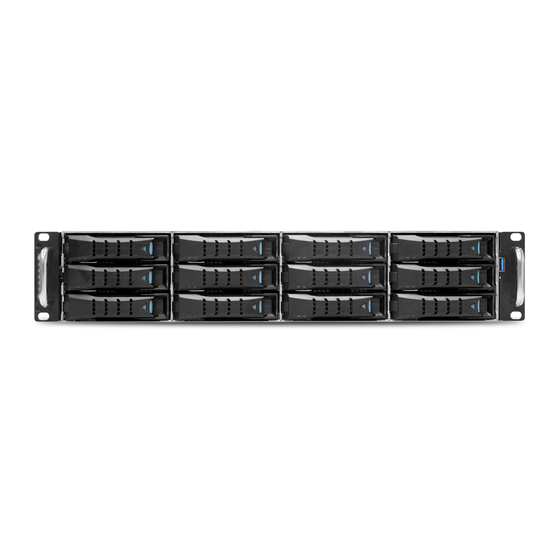
Chapter 1. Product Features SB202-LE User Manual Chapter 1. Product Features SB202-LE is a high density storage server that includes mother board, chassis, power supply, and fan. For more information about our product, please visit our website at http://www.aicipc.com/en. Before removing the subsystem from the shipping carton, visually inspect the physical condition of the shipping carton. -
Page 12: 1.2 Specifications
SB202-LE User Manual Chapter 1. Product Features 1.2 Specifications mm : 430 x 558.7 x 88.2 Expansion Dimensions PCIe 3.0 Slots (W x D x H) inches : 17 x 22 x 3.5 BIOS Type Motherboard AIC Server Board Lepus product family / 7th/6th Gen. - Page 13 SB202-LE User Manual Chapter 1. Product Features 1�3 Feature Front Panel ............................3.5" hotswap drive bays x 12 Power Switch System Power LED System HDD Activity LED LAN LED System Fault LED System ID LED System ID Switch System Reset Switch...
- Page 14 SB202-LE User Manual Chapter 1. Product Features Top view 550 W 1+1 redundant PSU 80+ Platinum 3 x 80x38mm hot swap fans...
-
Page 15: Chapter 2� Hardware Setup
Chapter 2� Hardware Setup SB202-LE User Manual Chapter 2. Hardware Setup 2�1 Central Processing Unit (CPU) 2�1�1 Processor Support The server board includes two processor sockets (LGA3647) that provides one or two processors of the Intel® Xeon® Processor Scalable Family and supports a Thermal Design Power (TDP) of up to 165W on selected models. - Page 16 Chapter 2. Hardware Setup SB202-LE User Manual While holding down the lever handle, with your other hand, lift open the Load Plate. Load plate Remove the protective cover from the CPU socket. Do not throw away the protective cover. It may be further used for RMA purposes.
- Page 17 SB202-LE User Manual Chapter 2. Hardware Setup Close the loading plate by pushing down the locking lever on the side. Slide the tip of the lever under the notch on the loading plate. Make sure the loading plate tab engages under the socket lever when fully closed.
-
Page 18: Cpu Heatsink Installation
Chapter 2. Hardware Setup SB202-LE User Manual 2�1�3 CPU Heatsink Installation Apply thermal grease onto the heatsink and position the heatsink onto the CPU socket. Make certain that the heatsink is accurately positioned. Tighten the four screws in a diagonal sequence. Secure the screws a couple of turns until the screws are tightly secured and the heatsink is fastened onto the server board. -
Page 19: System Memory Setup
SB202-LE User Manual Chapter 2. Hardware Setup 2�2 System Memory Setup This server board supports 4 DIMM memory slots with 2 channel and a memory capacity of up to 64G. 2�2�1 DIMM Installation Unlock the dimm socket by pressing the retaining clips outward. -
Page 20: Dimm Location
Chapter 2. Hardware Setup SB202-LE User Manual 2�2�2 DIMM Location 2�2�3 Dimm Slot Installation Order Populate the DIMM slots in the following order. DIMM NUMBER DIMM ARRANGEMENT JDIMMB1 JDIMMB0 CPU0 JDIMMA1 JDIMMA0 2 DIMMs JDIMM_A0 JDIMM_B0 CPU1 JDIMMB1 JDIMMB0 DIMM NUMBER... -
Page 21: Top Cover
SB202-LE User Manual Chapter 2. Hardware Setup 2�3 Top Cover 2�3�1 Removing the Top Cover Press the release button x 2 on both sides of the chassis. Slide the top cover towards the rear end of the system barebone. -
Page 22: Power Supply Unit Module
Chapter 2. Hardware Setup SB202-LE User Manual 2�4 Power Supply Unit Module 2�4�1 Replacing the Power Supply Unit Press the latch to release the module and pull the handle to remove the module out of the chassis. Push the replaced power supply unit into the chassis. Ensure that the module... -
Page 23: Fan Module
SB202-LE User Manual Chapter 2. Hardware Setup 2�5 Fan Module 2�5�1 Replacing the Fan Unplug the cables and connectors from the fan. Pull the fan module from the node. Check to carefully dislodge the rubber connectors from the attached bracket. -
Page 24: Hard Disk Drive
Chapter 2. Hardware Setup SB202-LE User Manual 2�6 Hard Disk Drive 2�6�1 Replacing the Hard Disk Drive Press the release button the tray lever to loosen the lever. Pull the tray lever outward completely. Pull the tray out of the system. -
Page 25: Hdd Backplane
SB202-LE User Manual Chapter 2. Hardware Setup 2�7 HDD Backplane 2�7�1 Replacing the HDD Backplane Detach the cables and hard disk drives from the backplane module. Release the module by shifting the hook. islodge the screws on the module. -
Page 26: Slide Blade Installation
Chapter 2. Hardware Setup SB202-LE User Manual 2�8 Slide Blade Installation Pull on the ‘’Front-Release’’to unlock the inner channel from the Slide Assembly. Release the Detent-Lock and push Middle Channel inwards to retract Middle Channel. - Page 27 SB202-LE User Manual Chapter 2. Hardware Setup Optional: Remove Metal Spacer for Aluminium Racks Metal Spacer Aligning the Front Bracket with the Mounting Hole. Push in to assembly the Front Bracket onto the Rack.
- Page 28 Chapter 2. Hardware Setup SB202-LE User Manual Now the bracket is fixed onto the Rack. (Optional M6x10L screws are to secure the rails with posts if needed.) Refer to step 3 and 4 to assemble the End Bracket onto the Rack.
- Page 29 SB202-LE User Manual Chapter 2. Hardware Setup Assemble the inner channel onto the chassis using thescrews provided. Push the chassis with inner channels into Slide to complete Rack Installation.
-
Page 30: Chapter 3�Hardware Settings
Chapter 3�Hardware Settings SB202-LE User Manual Chapter 3. Motherboard Settings This section provides illustrations that display the internal jumpers, connectors, and system LED indicators. 3�1 Block Diagram VCCcore = PXC1410A + TDA2132 x4 Mini-SAS HD Conn. VCCsa LSISAS3008 TDA2132 x1... -
Page 31: Content List
SB202-LE User Manual Chapter 3. Motherboard Settings 3�2 Content List Connector/Jumper/Header Location Connector/Jumper/Header Location DIMM_A0 SATA Port (SATA 3.0, (DDR4, Blue, J8C1 SATA3, J43 6 Gbit/s) Address:0xA0) CPU Fan, PIN SATA Port (SATA 3.0, SATA4, J42 Header 6 Gbit/s) System FAN5 Pin SATA Port (SATA 3.0,... - Page 32 SB202-LE User Manual Chapter 3. Motherboard Settings Connector/Jumper/Header Location Connector/Jumper/Header Location LAN3, LAN4 Port PCI Express Slot (RJ-45)*2 OPTIONAL (x1 Slot, w/x1 link) WITH BTO LSI SAS3008 LED1 USB Port (USB 3.0)*2 Action LED, Green LSI SAS3008 Error VGA Port (D-Sub) /...
-
Page 33: Layout
SB202-LE User Manual Chapter 3. Motherboard Settings 3�3 Layout 1 2 3 4... -
Page 34: Connector And Jumper
SB202-LE User Manual Chapter 3. Motherboard Settings 3�4 Connector and Jumper 2 CPU Fan (J14) 23 SATA SGPIO Pin 26 Front USB2.0 Header Header (J34) (blue) (FP_USB_1) 10 11 12 13 3 System Fan 1/Fan2/Fan3/ Fan4/Fan5: J50,J49, J48, J47, J15... - Page 35 SB202-LE User Manual Chapter 3. Motherboard Settings 33 Front Panel Header: 45 SPI Bus Select (J20) Jumper (J111) VCC3_AUX PWRLED+ IDLED+ IDLED- PWRLED- Setting J111 SYS_FAULT1- HDDLED+ PCH to SPI Default Pin1-3 and 4-6 Closed SYS_FAULT2- HDDLED- BMC to SPI...
-
Page 36: 3.5 System Led Indicator
SB202-LE User Manual Chapter 3. Motherboard Settings 3.5 System LED Indicator 3�5�1 Internal LED LED5 LED3 LED4 LED1 LED2... - Page 37 SB202-LE User Manual Chapter 3. Motherboard Settings State Description The LED shuts off when the SAS controller not active and can not SAS3008 be detected or properly initiated. Action LED The LED blinks per second to Blinking Green indicate that the SAS controller is active and working normally.
-
Page 38: Front Panel Led
SB202-LE User Manual Chapter 3. Motherboard Settings 3�5�2 Front Panel LED Green System is on. Power System is off. Yellow (Blinking) Disk activity is detected. Hard Disk Drive No disk activity is detected. LAN1 activity is detected. Yellow (Blinking) LAN1 LAN1 is not active. -
Page 39: Rear Panel Led
SB202-LE User Manual Chapter 3. Motherboard Settings 3�5�3 Rear Panel LED Green (Blinking) LAN* activity is detected. LAN* (Right) LAN* is not active. LAN cable is not connected. 100M: Green LAN* (Left) Status LED 10M/ No connection: Off Green (Blinking) LAN1 activity is detected. -
Page 40: Hdd Backplane: 2 Bay
SB202-LE User Manual Chapter 3. Motherboard Settings 3�6 HDD Backplane: 2 Bay 3�6�1 Placement Top view HDD0 HDD0 HDD1 Bottom view SATA1 SATA0 JPWR JLED_E HD_ACT_SW HD_ACT_SW 3�6�2 Connector BP Power (JPWR) Activity Selection (HD_ACT_SW0/HD_ACT_SW1) HDDIN0 SASIN0 Open: Standard. 1. On : And 5Hz on DAS, for SSD320. -
Page 41: Led Indicator
SB202-LE User Manual Chapter 3. Motherboard Settings 3�6�3 LED Indicator LED0 LED0 LED1 LED1 Blue (On) Link up Blue (Blinking) Activity detected SATA HD Link Blue (Off) Link down Status(LED0,LED1) Red (On) HDD error (external control only) Red (Off) HDD Normal... -
Page 42: Hdd Backplane: 12 Bay
SB202-LE User Manual Chapter 3. Motherboard Settings 3�7 HDD Backplane: 12 Bay 3�7�1 Placement Top view JMCU_UART JFAN1 JEXP_UART JI2C0 JFAN3 JMCU_DBG JI2C4 JPMBUS JFAN2 JI2C3 JEXP2 JFAN4 Flash Expander Sensor Sensor JPWR1 JPWR2 JFRONT SASHD3 SASHD2 SASHD1 Bottom view... -
Page 43: Connector
SB202-LE User Manual Chapter 3. Motherboard Settings 3�7�2 Connector Power Connector (JPWR1) Description Description +12V +12V +3.3V MUTE_L +5VSTBY PSU_N1 PS_ON_L Power Connector (JPWR2) Description Description +12V +12V +12V +12V... - Page 44 SB202-LE User Manual Chapter 3. Motherboard Settings I2C Connector (JI2C0, JI2C3, JI2C4) Description I2C_CLOCK I2C_DATA FAN Connector (JFAN1, JFAN2, JFAN3, JFAN4) Description +12V TACH Console for Expander (JEXP_UART) Description Description DEBUG_RXD SMART_RXD DEBUG_TXD SMART_TXD Console for MCU (JMCU_DBG) Description MCU_RXD...
-
Page 45: Led Indicator
SB202-LE User Manual Chapter 3. Motherboard Settings 3�7�3 LED Indicator Fail Fail Fail Fail SASHD Status LED LED2 LED1 LED5... - Page 46 SB202-LE User Manual Chapter 3. Motherboard Settings Blue (On) HDD present HDD Activity is detected or has located HDD Activity LEDs Blue (Blinking) HDD(slow) HDD is not connect or is power off. No control bit is set or set by any of the following bits: 1.
-
Page 47: Jumper
SB202-LE User Manual Chapter 3. Motherboard Settings 3�7�4 Jumper JMD_SEL JMCU_RST Open Normal, default JMCU_RST Close Reset MCU Open Normal, default JMD_SEL Close Boot loader mode 2.54mm Header for Front I/O (JFRONT) • Fan number select Pin[5,6] Pin [3,4] Pin [1,2] Fan no�... -
Page 48: Drive Slot Map
SB202-LE User Manual Chapter 3. Motherboard Settings 3�7�5 Drive Slot Map... -
Page 49: Chapter 4. Bios Configuration Settings
Chapter 4. BIOS Configuration Settings SB202-LE User Manual Chapter 4. BIOS Configuration Settings This chapter demonstrates how to configure the UEFI BIOS settings in your system device. You can enter the BIOS screen during system startup. To start the BIOS setup utiility, •... -
Page 50: Bios Menu
SB202-LE User Manual Chapter 4. BIOS Configuration Settings 4�2 BIOS Menu Press and to select the options of the menu bar. Press Enter to access the option screen. Menu Description Displays system information such as CPU bus speed, system memory speed, total installed Main memory, current EFI language, and system date &... -
Page 51: Main
SB202-LE User Manual Chapter 4. BIOS Configuration Settings 4�3 Main Lepus Main Option Key: 4�3�1 Main Main System time Configures current time. System date Configures current date. -
Page 52: Advanced
SB202-LE User Manual Chapter 4. BIOS Configuration Settings 4�4 Advanced Advanced Option Key: 4�4�1 Trusted Computing Displays Trusted Computing settings. Trusted Computing Security Device Support Enable Disable 4�4�2 ACPI Settings Displays system ACPI parameters. ACPI Settings Security Device Support Enable... -
Page 53: 4.4.3 Onboard Device Configuration
SB202-LE User Manual Chapter 4. BIOS Configuration Settings 4.4.3 Onboard Device Configuration Displays Onboard Device Configuration. Onboard Device Configuration Onboard LAN #1 Onboard LAN #2 Enable Disable Onboard LAN #3 Onboard LAN #4 Load Onboard LAN#1 Option ROM Load Onboard LAN#2... -
Page 54: S5 Rtc Wake Settings
SB202-LE User Manual Chapter 4. BIOS Configuration Settings 4�4�6 S5 RTC Wake Settings Enable system to wake from S5 using RTC alarm. S5 RTC Wake Settings Disable Fixed Time Dynamic Time Wake up hour Select 0-23. Wake up minute Wake System from S5 Wake up Minute Select 0-59 for Minute. -
Page 55: Chipset
SB202-LE User Manual Chapter 4. BIOS Configuration Settings 4�5 Chipset Chipset Option Key: 4.5.1 Intel Server Platform Services Configuration Displays Intel Server Platform Services Parameters. Intel Server Platform Services Configuration Intel Server Platform Enable Disable Services Power Measurement Enable Disable... -
Page 56: 4.5.3 South Bridge Configuration
SB202-LE User Manual Chapter 4. BIOS Configuration Settings 4.5.3 South Bridge Configuration Displays PCH Parameters. South Bridge Configuration Intel PCH RC Version Read only. Intel PCH SKU Name Read only. Intel PCH Rev ID Read only. DeepSx Power Policies Enable in S4-S5... -
Page 57: Security
SB202-LE User Manual Chapter 4. BIOS Configuration Settings 4�6 Security Security Option Key: 4�6�1 Security BIOS provide a supervisor password protection scheme during POST and Setup. Supervisor password can be used to prevent unauthorized users from gaining access to setup and booting the system. -
Page 58: Server Management
SB202-LE User Manual Chapter 4. BIOS Configuration Settings 4�7 Server Management Server Management Option Key: 4�7�1 FRB-2 Timer FRB-2 Timer: Configures FRB-2 timer (POST timer). FRB-2 Timer timeout: Enter value Between 3 to 6 min for FRB-2 Timer Expiration value. -
Page 59: System Event Log
SB202-LE User Manual Chapter 4. BIOS Configuration Settings OS Watchdog OS Watchdog Timer Enable Disable OS Wtd Timer timeout 5 minutes 10 minutes 15 minutes 20 minutes OS Wtd Timer Policy Do Nothing Reset Power Down Power Cycle 4�7�3 System Event Log A report mechanism that captures system exception events such as memory error, PCI-E error, etc. -
Page 60: Boot
SB202-LE User Manual Chapter 4. BIOS Configuration Settings 4�8 Boot Boot Option Key: 4�8�1 Boot Setup Prompt Timeout: Displays the number of seconds to wait for setup activation key. Bootup NumLock State:Select the keyboard NumLock state. Quiet Boot:Configures Quiet Boot option. -
Page 61: Save And Exit
SB202-LE User Manual Chapter 4. BIOS Configuration Settings 4�9 Save and Exit Save and Exit Option Key: 4�9�1 Save and Exit Save and Exit Save Changes and Exit Exit system setup after saving the changes. Discard Changes and Exit system setup without saving any changes. -
Page 62: Chapter 5. Bmc Configuration Settings
Chapter 5. BMC Configuration Settings SB202-LE User Manual Chapter 5. BMC Configuration Settings 5�1 Login NOTE This feature works with the JAVA 6 run time installed console environment. The IP address below is an example using the default IP setting. The IP address is configurable. -
Page 63: Web Gui
SB202-LE User Manual Chapter 5. BMC Configuration Settings 5�2 Web GUI 5�2�1 Menu Bar Click to select the options of the menu bar. Menu Description The Dashboard page gives the overall information about the status of a Dashboard device. Sensor The Sensor Readings page displays all the sensor related information. -
Page 64: User Information And Quick Button
SB202-LE User Manual Chapter 5. BMC Configuration Settings 5�2�2 User Information and Quick Button The user information and quick access buttons are located at the top right corner. It displays the logged-in user, his/her privilege and the four quick buttons allowing you to perform different functions. - Page 65 SB202-LE User Manual Chapter 5. BMC Configuration Settings 5�2�3 Dashboard The Dashboord page displays device, system, and network information. Click Dashboard on the menu bar to view the overall information of the server. 5�2�4 Sensor The Sensor page displays the status and records on related sensors.
-
Page 66: System Inventory
SB202-LE User Manual Chapter 5. BMC Configuration Settings 5�2�5 System Inventory The System Inventory page displays network information, including Vendor name, Model, and Sofware version. Click System Inventory on the menu bar to open. 5�2�6 FRU Information The FRU Information page displays Basic Information, Chassis Information, Board Information and Product Information of the FRU device. -
Page 67: Logs And Reports
SB202-LE User Manual Chapter 5. BMC Configuration Settings 5�2�7 Logs and Reports The System Inventory page displays IPMI Event Log and Video Log. Click Logs and Reports from the menu bar select Event Log or Video Log to view the contents. -
Page 68: Settings
SB202-LE User Manual Chapter 5. BMC Configuration Settings 5�2�8 Settings The Settings page displays the configuration settings for Date & Time, External User Services, KVM Mouse Setting, Log Settings, Media Redirection Settings, Network Settings, PAM Order Settings, Platform Event Filter, Services, SMTP Settings, SSL... - Page 69 SB202-LE User Manual Chapter 5. BMC Configuration Settings Settings Menu and Option Keys: Settings Date and Time LDAP/E-directory Active directory Radius Settings Settings Settings External User Services General Advanced General Role General Role Radius Radius Settings Groups Settings Groups Settings...
-
Page 70: Remote Control
SB202-LE User Manual Chapter 5. BMC Configuration Settings 5�2�9 Remote Control The Remote Control page displays the configuration for power control and remote KVM. Click Java Console to start the JViewer video redirection. - Page 71 SB202-LE User Manual Chapter 5. BMC Configuration Settings Click Launch KVM to open the Remote KVM page.
- Page 72 SB202-LE User Manual Chapter 5. BMC Configuration Settings Procedure To Start KVM Click Start KVM to start the H5Viewer video redirection. Click Browse to select CD Image. Click Start Media to redirect the selected CD image file to the Host.
- Page 73 SB202-LE User Manual Chapter 5. BMC Configuration Settings Remote KVM Menu and Option Keys: Button Description Start KVM Starts the H5Viewer video redirection. Stop KVM Stops the H5Viewer video redirection. Pause Video This option is used for pausing Console Redirection.
- Page 74 SB202-LE User Manual Chapter 5. BMC Configuration Settings This menu item can be used to act as the Right <Ctrl> right-side <CTRL> key when in Console Redirection. This menu item can be used to act as Right <Alt> the right-side <ALT> key when in Console Redirection.
-
Page 75: Power Control
SB202-LE User Manual Chapter 5. BMC Configuration Settings 5�2�10 Power Control The Power Control page allows you to view and control the power of your server. To open Power Control, click Power Control from the menu bar. The various options of Power Control are given below. -
Page 76: Chassis Identify Control
SB202-LE User Manual Chapter 5. BMC Configuration Settings 5�2�11 Chassis Identify Control The Chassis Identify Control page displays the BMC’s UID control information. Users can change the Identify LED behavior on this page. Click Chassis Identify Control from the menu bar. Select Off/On to control UID LED. - Page 77 SB202-LE User Manual Chapter 5. BMC Configuration Settings 5�2�13 Maintenance This Maintenance page displays the configuration settings for Backup Configuration, Firmware Image Location, Firmware Information, BIOS Information, Fimware Update, Preserve Configuration, Restore Configuration, Restore Configuration, and Restore Factory Defaults.
-
Page 78: Maintenance
SB202-LE User Manual Chapter 5. BMC Configuration Settings Maintenance Procedure 1. Click Check All to backup the selected configuration items. The Backup Configuration page will appear Click Download Config to save the backup file to the client system Backup Configuration 2. -
Page 79: Sign Out
SB202-LE User Manual Chapter 5. BMC Configuration Settings 5�2�14 Sign out To log out of the BMC: Method 1: Click Sign out from the menu bar. The Logout dialog box will pop out. Method 2: Click the root quick button on the top right corner of the screen. -
Page 80: Chapter 6� Technical Support
Chapter 6� Technical Support SB202-LE User Manual Chapter 5. BMC Configuration Settings Taiwain, Global Headquarters South California, United States Address: No� 152, Section 4, Address: 21808 Garcia Lane Linghang N� Rd, Dayuan District, City of Industry, CA 91789, Taoyuan City 337, Taiwan...
Need help?
Do you have a question about the SB202-LE and is the answer not in the manual?
Questions and answers