Table of Contents
Advertisement
Quick Links
Advertisement
Table of Contents

Related Manuals for AIC HA202-PV


Summary of Contents for AIC HA202-PV
- Page 1 HA202-PV Storage Barebone User's Manual UM_HA202-PV_v1.1_061119...
-
Page 2: Table Of Contents
Table of Contents Preface ������������������������������������������������������������������������������������������������� i Safety Instructions ������������������������������������������������������������������������������ ii About This Manual ������������������������������������������������������������������������������ iv Chapter 1� Product Features �������������������������������������������������������������� 1 1�1 Box Content ���������������������������������������������������������������������������������������1 1.2 Specifications������������������������������������������������������������������������������������2 1�3 Features ��������������������������������������������������������������������������������������������3 Chapter 2� Hardware Setup ���������������������������������������������������������������� 7 2�1 Central Processing Unit Setup ����������������������������������������������������������7 2.1.1 Processor Installation ..................7 2.1.2 CPU heatsink for each CPU ................ - Page 3 Chapter 3� Hardware Settings ���������������������������������������������������������� 24 3�1 Motherboard Block Diagram ������������������������������������������������������������24 3�2 Motherboard Content List ����������������������������������������������������������������25 3�3 Motherboard Layout ������������������������������������������������������������������������26 3�4 Internal Connectors/Jumpers ���������������������������������������������������������27 3�5 System LED Indicator ����������������������������������������������������������������������32 3.5.1 Front Panel LED ....................32 3.5.2 Rear I350 LAN LEDs..................32 3.5.3 Rear PCH LAN LEDs..................
- Page 4 4�8 Exit ��������������������������������������������������������������������������������������������������57 4.8.1 Exit ........................57 Chapter 5. BMC Configuration Settings �������������������������������������������� 58 5�1 Method 1 (Use the BIOS Setup) ��������������������������������������������������������58 5�2 Method 2 (Use a Dos Tool - Syscheck) ���������������������������������������������61 5�3 Login �����������������������������������������������������������������������������������������������63 5�4 Web GUI �����������������������������������������������������������������������������������������64 5.4.1 Menu Bar ......................64 5.4.2 User Information and Quick Button ...............
- Page 5 Copyright © 2018 AIC, Inc� All Rights Reserved� This document contains proprietary information about AIC products and is not to be disclosed or used except in accordance with applicable agreements.
- Page 6 Document Release History Release Date Version Update Content June User's Manual release to public. 2018 June Memory update 2019...
-
Page 7: Preface
Disclaimer AIC shall not be liable for technical or editorial errors or omissions contained herein. The information provided is provided "as is" without warranty of any kind. To the extent permitted by law, neither AIC or its affiliates, subcontractors or suppliers will be liable for incidental, special or consequential damages including downtime cost;... -
Page 8: Safety Instructions
Safety Instructions Before getting started, please read the following important cautions: • All cautions and warnings on the equipment or in the manuals should be noted. • Most electronic components are sensitive to electrical static discharge. Therefore, be sure to ground yourself at all times when installing the internal components. •... - Page 9 • If one of the following situations arise, the equipment should be checked by service personnel: 1. The power cord or plug is damaged. 2. Liquid has penetrated the equipment. 3. The equipment has been exposed to moisture. 4. The equipment does not work well or will not work according to its user manual. 5.
-
Page 10: About This Manual
This document pellucidly presents a brief overview of the product design, device installation, and firmware settings for HA202-PV. For the latest version of this user's manual, please refer to the AIC website: https://www.aicipc.com/en/productdetail/50946. -
Page 11: Chapter 1� Product Features
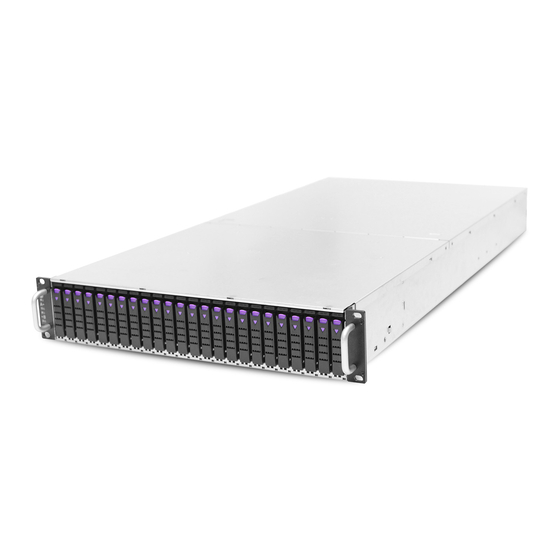
HA202-PV User Manual HA202-PV User Manual Chapter 1. Product Features HA202-PV is a 2U high density storage server with 24 hot swap bays for dual-port NVMe SSDs (U.2). For more information about our product, please visit our website at http://www.aicipc.com/en/index. -
Page 12: 1.2 Specifications
HA202-PV User Manual Chapter 1. Product Features 1.2 Specifications mm : 435 x 911 x 87 Expander Boards Dimensions 2 x 64-port Broadcom/PLX 9765 PCIe switch board (per node) (W x D x H) inches : 17.1 x 35.9 x 3.4... -
Page 13: 1�3 Features
Chapter 1. Product Features 1�3 Features HA202-PV is a reliable 2U storage server barebone with 24 hotswap drives bays. This product is designed to accommodate the AIC-patented serverboard, Pavo, which supports two Intel® Xeon® Scalable Processors and 16 DDR4 DIMM to offer greater perfomance, efficiency, and utility for our customers. - Page 14 HA202-PV User Manual Chapter 1. Product Features Front Panel HA202-PV provides 1 system button (power) and 2 LED indicators for each node (A & B node: power and warning LED). 24 x 2.5" hotswap drive bays Power Button Canister A Power LED...
- Page 15 Rear Panel HA202-PV provides 3 PCIe slots per node (1 x PCIe x16 , 1 x PCIe Gen3 x8 , and 1 x OCP Mezzanine card V2.0), 4 LAN ports (2x 10GbE SFP+, 2 x GbE Rj45), 1 GbE RJ45 port dedicated to BMC management, 2 USB ports (3.0 Type A), 1 VGA port, and 1 audio jack for...
- Page 16 HA202-PV User Manual Chapter 1. Product Features Major Components HA202-PV provides 24 x 2.5" external hotswap drive bays. HA202-PV Top view Node top view...
-
Page 17: Chapter 2� Hardware Setup
Chapter 2� Hardware Setup HA202-PV User Manual Chapter 2. Hardware Setup This section describes a simple instruction guide for installing the hardware components on the serverboard system. Turn off and unplug all system and peripheral devices before proceeding. 2�1 Central Processing Unit Setup The serverboard supports dual Xeon scalable processors and Socket P0 (LGA-3647). - Page 18 Chapter 2. Hardware Setup HA202-PV User Manual Processor Socket Assembly: The server board includes two processor sockets (LGA-3647), supports one or two of the Intel® Xeon® Processor Scalable Family and has a Thermal Design Power (TDP) of up to 165W on selected models.
- Page 19 HA202-PV User Manual Chapter 2. Hardware Setup The PHM sits level with the processor socket assembly. The PHM is NOT installed properly if it does not sit level with the processor socket assembly. Once the PHM is seated over the processor socket assembly, the four heat sink torque screws must be tightened in order as shown below.
-
Page 20: Cpu Heatsink For Each Cpu
Chapter 2. Hardware Setup HA202-PV User Manual 2�1�2 CPU heatsink for each CPU CPU 1 CPU 0 heatsink inside each node... -
Page 21: 2�2 System Memory
HA202-PV User Manual Chapter 2. Hardware Setup 2�2 System Memory 2�2�1 Dual Processor This server board supports up to sixteen DDR4 2400 and 2666 Registered ECC DRAM/ Load-Reduced DIMM (LRDIMM). DIMMC DIMMJ DIMMB DIMMH DIMMA1 DIMMG1 DIMMA2 DIMMG2 CPU0 CPU0... -
Page 22: Recommended Dimm Installation Order
Chapter 2. Hardware Setup HA202-PV User Manual 2�2�2 Recommended Dimm Installation Order JDIMMC JDIMMJ JDIMMB JDIMMH JDIMMA1 JDIMMG1 JDIMMA2 JDIMMG2 DIMM Numbers DIMM ARRANGMENT CPU0 CPU1 CPU0 CPU0 CPU1 CPU1 2 DIMMs JDIMM_C JDIMM_J JDIMMD2 JDIMMK2 JDIMMD1 JDIMMK1 JDIMME JDIMML... - Page 23 HA202-PV User Manual Chapter 2. Hardware Setup JDIMMC JDIMMJ JDIMMB JDIMMH JDIMMA1 JDIMMG1 JDIMMG2 JDIMMA2 JDIMM_J JDIMM_C JDIMM_B JDIMM_H CPU0 CPU0 CPU1 CPU1 JDIMM_A1 JDIMM_G1 JDIMM_D1 JDIMM_K1 JDIMM_F JDIMM_M JDIMMD2 JDIMMK2 JDIMMD1 JDIMMK1 JDIMME JDIMML JDIMMF JDIMMM JDIMMC JDIMMJ JDIMMB...
-
Page 24: Dimm Installation
Chapter 2. Hardware Setup HA202-PV User Manual 2�2�3 DIMM Installation Step 1 Unlock the dimm socket by pressing the retaining clips outward. Step 2 Insert the memory module into the slot. Make sure that the dimm notch is accurately positioned. -
Page 25: 2�3 Top Cover
HA202-PV User Manual Chapter 2. Hardware Setup 2�3 Top Cover 2�3�1 Installing the top cover Position the top cover on the chassis and secure the screws x 10 pcs. 2�3�2 Removing the top cover Remove the screws on the top cover to remove the cover. -
Page 26: 2�4 Power Supply Unit Module
Chapter 2. Hardware Setup HA202-PV User Manual 2�4 Power Supply Unit Module 2�4�1 Installing the Power Supply Unit Push module into the enclosure. Make certain that the module is fully inserted to complete installation. 2�4�2 Removing the Power Supply Unit Push the latch on the module and pull the tray handle to remove. -
Page 27: 2�5 Node
HA202-PV User Manual Chapter 2. Hardware Setup 2�5 Node 2�5�1 Installing the Node Loosen the retaining screw x 2 pcs on the module and pull the tray handle. 2�5�2 Removing the Node Push the module into the enclosure and tighten the retaining screws. Make certain to fully insert the module into the chassis before securing the screws. -
Page 28: 2�6 Fan Module
Chapter 2. Hardware Setup HA202-PV User Manual 2�6 Fan Module 2�6�1 Installing the fan module Insert the module into the node. Make certain that the four rubber connectors are firmly inserted. Secure the top cover of the node. ... -
Page 29: 2�7 Hard Disk Drive
HA202-PV User Manual Chapter 2. Hardware Setup 2�7 Hard Disk Drive 2�7�1 Installing the hard disk drive Insert the hard disk drive into the tray Secure the screws x 4 pcs (Screws may vary according to different types of hard drive disks). -
Page 30: 2�8 Hdd Backplane Module
Chapter 2. Hardware Setup HA202-PV User Manual 2�8 HDD Backplane Module 2�8�1 Installing the HDD Backplane Insert the HDD module into the HDD backplane slot and secure the screws x 9 pcs. 2�8�2 Removing the HDD Backplane Remove the screws on the HDD backplane and pull the module out of the enclosure. -
Page 31: 2�9 Slide Rail Installation
HA202-PV User Manual Chapter 2. Hardware Setup 2�9 Slide Rail Installation Removing the inner slide rail. Pull the slide rail open by pressing the trigger downward. Pull chassis inner rail out Press the trigger down to release Mounting the inner side of the slide rail. - Page 32 Chapter 2. Hardware Setup HA202-PV User Manual Attach the outer of cabinet to the slide rail. Insert the stag into the upper and lower square holes on rail from the back of rail. Push the safety lock forward to secure the bracket. Be certain to check if the safety lock is in disenaged position before mounting the brackets.
- Page 33 HA202-PV User Manual Chapter 2. Hardware Setup Mount the chassis into the cabinet. Insert the inner side of chassis into the cabinet. Check if the ball retainer is fully opened before installing the chassis. It may cause catastrophic damage to the chassis if ball retainer is not in fully open position while mounting the chassis.
-
Page 34: Chapter 3� Hardware Settings
Chapter 3� Hardware Settings HA202-PV User Manual Chapter 3. Hardware Settings This section describes the jumpers, internal connectors, and internal LED settings. 3�1 Motherboard Block Diagram... -
Page 35: 3�2 Motherboard Content List
HA202-PV User Manual Chapter 3. Hardware Settings 3�2 Motherboard Content List Connector/Jumper/Header Location Connector/Jumper/Header Location Power Supply J87: 12V & 5VSB 6A 23 ME Recovery Mode J35 Connector Pin-out per pin. VDR Supply AIC Open Rack J86: 12V Connector Pin-out... -
Page 36: 3�3 Motherboard Layout
HA202-PV User Manual Chapter 3. Hardware Settings 3�3 Motherboard Layout 16 DIMM Sockets 39 23 38 CPU0 CPU1 25 29 30 31 32 21 16 10 44 43... -
Page 37: 3�4 Internal Connectors/Jumpers
HA202-PV User Manual Chapter 3. Hardware Settings 3�4 Connector and Jumper 6 Front VGA Header: J7 7 & 8 COM Header: J11, J12 15 16 DDC_CLKO AVSYNCO VGA_5V AHSYNCO DACBO DDC_DATAO DACGO DACRO 13 Debug Port Header: J13 CLK_DP80 PCH_CS0_N... - Page 38 HA202-PV User Manual Chapter 3. Hardware Settings 25 29 30 16 10 10 Front USB 2.0: 14 BMC Debug 16 IPMB Header: 25 FAN Front Port: J14 Header: J39 34 VRM SMB Header: J24 28 LCM Header: J9 29 PCH SGPIO...
- Page 39 HA202-PV User Manual Chapter 3. Hardware Settings 9 Front USB 3.0 Port: J16 18 Intruder 37 BMC Fan Header: J51 Header: J47 INTRUDER...
- Page 40 1 Power Supply Connector 2 VRD Supply Connector 5 Front Panel Header: J81 Pin-out: J87 Pin-out: J86 +12V +12V +12V +12V +12V +12V +12V +12V +12V +5VSB POWER OK PS_ON# 24 AIC OPEN RACK Header: 26 MDI PHY Port Header:...
- Page 41 HA202-PV User Manual Chapter 3. Hardware Settings 31 32 15 CMOS Jumper Setting: 21 Speaker Header: J48 22 FLASH Security override: SPEAKER Setting Setting Pin1-2 Normal (Default) Short FLASH Security Pin2-3 Clear override CMOS Open Normal (Default) 32 Password Clear: J31...
-
Page 42: 3�5 System Led Indicator
HA202-PV User Manual Chapter 3. Hardware Settings 3�5 System LED Indicator 3�5�1 Front Panel LED Yellow System is On. System is in Standby; System is off, but has Power Blinking AC power. System has no AC power. Blue UID activity is detected. -
Page 43: Rear Pch Lan Leds
HA202-PV User Manual Chapter 3. Hardware Settings 3�5�3 Rear PCH LAN LEDs Green LAN1 activity is detected. LED5 LAN1 is not active. Green LAN1 link is detected LED7 LAN1 is not linked. Green LAN0 activity is detected LED6 LAN0 is not linked. -
Page 44: Rear Uid Led & Internal Led
HA202-PV User Manual Chapter 3. Hardware Settings 3�5�4 Rear UID LED & Internal LED UID activity is detected. LED1 UID is not active. BMC Rack LAN activity is detected (Only for LED2 Rack). BMC Rack LAN is not active (Only for Rack). -
Page 45: 3�6 Hdd Backplane
HA202-PV User Manual Chapter 3. Hardware Settings 3�6 HDD Backplane 3�6�1 Layout... -
Page 46: Internal Connectors/Jumpers
HA202-PV User Manual Chapter 3. Hardware Settings 3�6�2 Internal Connectors/Jumpers Power Supply Connector Pin-out (J1) PSU PMBUS (J4) for Bezel (JBezel1) Bezel1_5V Bezel1_3V PIC_SDA5_R Power Supply Connector Pin-out (J3) PIC_SCL5_R Front penal (J2) POWER_SW P_STATUS_LED_GN CANISTER_P_PON P_STATUS_LED_RN CANISTER_S_PON P_STATUS_LED_GN +3VSTBY... -
Page 47: 3�7 Bridge Board
HA202-PV User Manual Chapter 3. Hardware Settings 3�7 Bridge Board 3�7�1 Layout 11 15... -
Page 48: Connector
HA202-PV User Manual Chapter 3. Hardware Settings 3�7�2 Connector I2C8SCL_G3 BMC_EXTRST# I2C8SDA_G3 I2C1SCL JVBATT_I2C 2C1SCL GPION0 I2C1SDA I2C1SDA GPIOO0 PSU_SMBCLK GPION1 PSU_SMBDAT GPIOO1 POWER_PSON JMB_PGD1 20 19 7 14 MB_POK POWER_PSON +5VSB_MB +12V +12V SW_PWR_BTN# JPWR1 JPWR_SW1 +12V 2 MB_SW2... -
Page 49: Chapter 4. Bios Configuration Settings
Chapter 4. BIOS Configuration Settings HA202-PV User Manual Chapter 4. BIOS Configuration Settings This chapter demonstrates how to configure the UEFI BIOS settings in your system device. You can enter the BIOS screen during system startup. To enter BIOS configuration settings, •... -
Page 50: 4�2 Bios Setup
HA202-PV User Manual Chapter 4. BIOS Configuration Settings 4�2 BIOS Setup 4�2�1 Menu Press and to select the options of the menu bar. Press Enter to access the option screen. Menu Description Main Displays basic system information and date & time. - Page 51 HA202-PV User Manual Chapter 4. BIOS Configuration Settings Step 2 There will be a message “Entering SETUP” displayed on the diagnostics screen. Step 3 Identify the BIOS version. NOTE For the official released version, the last digit of the BIOS version must end in a “0.“...
- Page 52 HA202-PV User Manual Chapter 4. BIOS Configuration Settings Step 4 Load Optimal Default Setting. Step 5 Save the setting and exit the BIOS setup utility.
-
Page 53: 4�3 Main
HA202-PV User Manual Chapter 4. BIOS Configuration Settings 4�3 Main Main Option Key: 4�3�1 Main Option Key Description System time Configures the current time. System date Configures the current date. -
Page 54: 4�4 Advanced
HA202-PV User Manual Chapter 4. BIOS Configuration Settings 4�4 Advanced Advanced Option Key: 4.4.1 Peripheral Configuration Peripheral Configuration PCIe SR-IOV Enable Disable PCIe ARI Enable Disable ARI Forward Enable Disable Spread Enable Disable Spectrum Redfish On/ Enable Disable 4.4.2 Video Configuration... - Page 55 HA202-PV User Manual Chapter 4. BIOS Configuration Settings MSR Lock Control Enable Disable Processor Configuration Extended APIC Enable Disable 128M 256M MMCFG Size 512M Common MMIO High Base RefCode Configuration MMIO High Granularity Size 256G 1024G Disable Minimum Serial Debug Message...
- Page 56 HA202-PV User Manual Chapter 4. BIOS Configuration Settings Check Platform Detect Enable Disable Erase-Arm NVDIMMs Enable Disable Restore NVDIMMs Enable Disable Memory Configuration Interleave NVDIMMs Enable Disable Custom Refresh Rate Min=0, Max=40 Auto 100 KHz SMB Clock Frequency 400 KHz...
- Page 57 HA202-PV User Manual Chapter 4. BIOS Configuration Settings Single Power Enable Disable Domain (SPD) Max Performance Boot performance Max Efficient mode Set by Intel Node Manager CPU P State Control Energy Enable Disable Efficient Turbo Turbo Mode Enable Disable CPU Flex Ratio...
-
Page 58: 4.4.4 Pch Configuration
HA202-PV User Manual Chapter 4. BIOS Configuration Settings 4.4.4 PCH Configuration PCH Configuration PCH Devices PCH state after G3 Last State SATA Controller Configure SATA as AHCI RAID Support Aggressive Link Power Enable Disable Management Alternate Device ID on Enable... - Page 59 HA202-PV User Manual Chapter 4. BIOS Configuration Settings Smart Response Enable Disable Technology PCH SATA Configuration 2 Seconds 4 Seconds RAID OROM prompt delay 6 Seconds 8 Seconds sSATA Controller Enable Disable Configure sSATA as AHCI RAID Support Aggressive Link Power...
- Page 60 HA202-PV User Manual Chapter 4. BIOS Configuration Settings SLP_LAN# Low on DC Enable Disable Power K1 off Enable Disable FPK Port 1-4 Enable Management Disable PCI Delay Enable Disable Optimization Compliance Test Enable Disable Mode PCI-E ASPM Support Per individual port...
- Page 61 HA202-PV User Manual Chapter 4. BIOS Configuration Settings Enable Disable Enable Disable Enable Disable NFER Enable Disable Enable Disable SEFE Enable Disable SENFE Enable Disable SECE Enable Disable PME SCI Enable Disable Hot Plug Enable Disable Advanced Error Enable Disable...
-
Page 62: H2O Ipmi Configuration
HA202-PV User Manual Chapter 4. BIOS Configuration Settings Auto Non Snoop Latency Manual Override Disable Non Snoop Min=0, Max=102 Latency Value PCH sSATA PCH PCIe LTR Configuration Configuration 1 ns 32 ns Non Snoop Latency 1024 ns 32768 ns Multiplier... -
Page 63: H2O Event Log Config Manager
HA202-PV User Manual Chapter 4. BIOS Configuration Settings 4.4.6 H2o Event Log Config Manager H2o Event Log Config Manager Console Serial Enable Disable Redirect VT_100 VT_100+ Terminal Type VT_UTF8 PC_ANSI 1200 2400 4800 9600 Baud Rate 19200 38400 57600 115200... -
Page 64: 4�5 Security
HA202-PV User Manual Chapter 4. BIOS Configuration Settings 4�5 Security Security Option Key: 4�5�1 Security Security Current TPM Not Detected TPM 1.2 TPM 2.0 Device TrEE Protocol Version Available Hidden Availability Disable and No operation Enable and Activate Operation Deactivate... -
Page 65: 4�6 Power
HA202-PV User Manual Chapter 4. BIOS Configuration Settings 4�6 Power Power Option Key: 4�6�1 Power Power Wake on PME Enable Disable... -
Page 66: 4�7 Boot
HA202-PV User Manual Chapter 4. BIOS Configuration Settings 4�7 Boot Boot Option Key: 4�7�1 Boot Boot Boot Type Dual Boot Type Legacy Boot Type UEFI Boot Type Quick Boot Enable Disable Quiet Boot Enable Disable Network Enable Disable Stack PXE Boot to... -
Page 67: 4�8 Exit
HA202-PV User Manual Chapter 4. BIOS Configuration Settings 4�8 Exit Exit Option Key: 4�8�1 Exit Save and Exit Exit Saving Changes Exit system setup and save your changes. Save Change Without Save your changes without exiting the system. Exit Exit Discarding Discard your changes when existing the system. -
Page 68: Chapter 5. Bmc Configuration Settings
Chapter 5. BMC Configuration Settings HA202-PV Chapter 5. BMC Configuration Settings Chapter 5. BMC Configuration Settings Insert Ethernet LAN cable into the BMC LAN port. There are two methods to setup BMC IP: BMC management port 5�1 Method 1 (Use the BIOS Setup) Step 1 BIOS SETUP ... - Page 69 HA202-PV Chapter 5. BMC Configuration Settings...
- Page 70 HA202-PV Chapter 5. BMC Configuration Settings Step 3 Type in the subnet mask address. Step 4 Type in the gateway address.
-
Page 71: 5�2 Method 2 (Use A Dos Tool - Syscheck)
HA202-PV Chapter 5. BMC Configuration Settings 5�2 Method 2 (Use a Dos Tool - Syscheck) Step 1 Type in "sc –lanset" Step 2 Modify the IP setting. NOTE Type 1 for selecting Static IP Mode or type 2 for selecting DHCP Mode. - Page 72 HA202-PV Chapter 5. BMC Configuration Settings Step 4 Type in the submask address. The IP address below is an example using a default IP setting. The IP address is configurable. Step 5 Configure the gateway address to complete the BMC IP setting.
-
Page 73: 5�3 Login
HA202-PV Chapter 5. BMC Configuration Settings 5�3 Login NOTE This feature works with JAVA 6 Runtime installed Console Environment The IP source default is DHCP. You can change the IP source to DHCP or Static by the BIOS utility or the system check. -
Page 74: 5�4 Web Gui
HA202-PV Chapter 5. BMC Configuration Settings 5�4 Web GUI 5�4�1 Menu Bar Click to select the options of the menu bar. Menu Description The Dashboard page gives the overall information about the status of Dashboard a device. Sensor The Sensor Readings page displays all the sensor related information. -
Page 75: User Information And Quick Button
HA202-PV Chapter 5. BMC Configuration Settings 5�4�2 User Information and Quick Button The user information and quick access buttons are located at the top right corner. It displays the logged-in user, his/her privilege and the four quick buttons allowing you to perform different functions. -
Page 76: Fru Information
HA202-PV Chapter 5. BMC Configuration Settings 5�4�3 Dashboard: The Dashboard page gives the overall information about the status of adevice. 5�4�4 Sensor The Sensor Readings page displays all the sensor related information. 5�4�5 FRU Information The FRU Information page displays Basic Information, Chassis Information, Board Information and Product Information of the FRU device. -
Page 77: Logs And Report
HA202-PV Chapter 5. BMC Configuration Settings 5�4�6 Logs and Report The System Inventory page displays IPMI Event Log and Video Log. Click Logs and Reports from the menu bar. 5�4�7 Settings The Settings page allows you to access various configuration settings. -
Page 78: Kvm Mouse Setting
HA202-PV Chapter 5. BMC Configuration Settings 5�4�8 KVM Mouse Setting The KVM Mouse Setting page allows you to configure the mouse mode to relative, absolute, and other. • For Windows OS environment, set mode to absolute. • For Linux OS environment, set mode to relative. - Page 79 HA202-PV Chapter 5. BMC Configuration Settings Launch KVM:...
-
Page 80: Chapter 6� Technical Support
Chapter 6� Technical Support www�aicipc�com Taiwain, Global Headquarters South California, United States Address: No� 152, Section 4, Address: 21808 Garcia Lane Linghang N� Rd, Dayuan District, City of Industry, CA 91789, Taoyuan City 337, Taiwan United States Tel: +886-3-433-9188 Toll free: +7-4997019998 Fax: +886-3-287-1818 Tel: +1-909-895-8989 Sales Email: sales@aicipc�com�tw...
Need help?
Do you have a question about the HA202-PV and is the answer not in the manual?
Questions and answers