Table of Contents
Advertisement
Available languages
Available languages
Quick Links
Advertisement
Table of Contents

Subscribe to Our Youtube Channel
Related Manuals for MKS Baratron 121A


Summary of Contents for MKS Baratron 121A
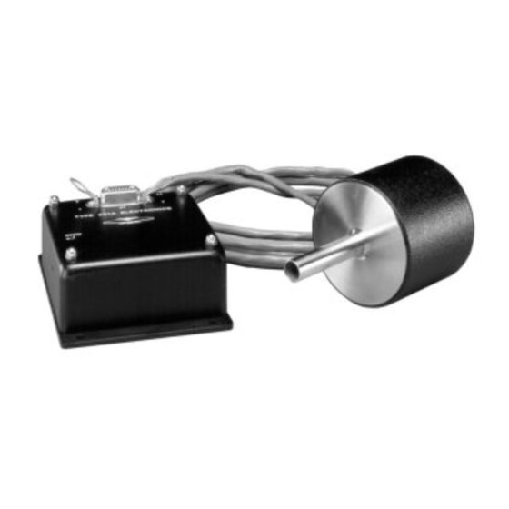
- Page 1 113733-P1 Rev C, 7/98 Instruction Manual ® MKS Baratron Type 121A Absolute Pressure Transducer Six Shattuck Road Fax: (978) 975-0093 Andover, MA 01810-2449 E-mail: mks@mksinst.com (800) 227-8766 or (978) 975-2350 Web site: http://www.mksinst.com...
- Page 2 MKS Instruments, Inc. (MKS) warrants that the equipment described above (the “equipment”) manufactured by MKS shall be free from defects in materials and workmanship for a period of one year from date of shipment and will for a period of two years from the date of shipment, correctly perform all date-related operations, including...
- Page 3 113733-P1 Rev C, 7/98 ® MKS Baratron Type 121A Absolute Pressure Transducer...
- Page 4 All rights reserved. No part of this work may be reproduced or transmitted in any form or by any means, electronic or mechanical, including photocopying and recording, or by any information storage or retrieval system, except as may be expressly permitted in writing by MKS Instruments, Inc.
-
Page 5: Table Of Contents
Table of Contents Table of Contents Pressure Transducer Safety Information.................. 1 Symbols Used in This Instruction Manual..............1 Symbols Found on the Unit ..................2 Safety Procedures and Precautions ................3 Sicherheitshinweise für den Druckmeßumformer..............5 In dieser Betriebsanleitung vorkommende Symbole ........... 5 Erklärung der am Gerät angebrachten Symbole ............ - Page 6 Table of Contents Setup..........................25 Sensor......................25 Electronics Unit .....................26 Pressure Connections ....................28 Standard Fitting .....................28 Optional Fittings....................28 Chapter Three: Overview .......................29 Type 121 Absolute Pressure Transducer ..............29 Sensor......................29 Electronics Unit .....................29 Electrical Connections....................30 Labels ........................31 Chapter Four: Operation ......................33 Warm Up and Start Up ....................33 How To Prepare for Maximum Bakeout ..............34 Disassembly ....................35 How To Reassemble the Unit After Bakeout ..............36...
- Page 7 Table of Contents Appendix D: High Pressure Fitting Selection ................. 49 Description ........................ 49 Index............................51...
- Page 8 Table of Contents...
- Page 9 List of Figures and Tables List of Figures and Tables Figures Figure 1: Sensor Dimensions....................25 Figure 2: Electronics Unit Horizontal Dimensions..............26 Figure 3: Electronics Unit Vertical Dimensions ..............27 Figure 4: Serial Number Label ....................31 Figure 5: Sensor Assembly....................34 Tables Table 1: Definition of Symbols Found on the Unit ..............2 Tabelle 2: Bedeutung der am Gerät angebrachten Symbole............6...
- Page 10 List of Figures and Tables viii...
-
Page 11: Pressure Transducer Safety Information
Pressure Transducer Safety Information Symbols Used in This Instruction Manual Pressure Transducer Safety Information Symbols Used in This Instruction Manual Definitions of WARNING, CAUTION, and NOTE messages used throughout the manual. Warning The WARNING sign denotes a hazard to personnel. It calls attention to a procedure, practice, condition, or the like, which, if not correctly performed or adhered to, could result in injury to personnel. -
Page 12: Symbols Found On The Unit
Symbols Found on the Unit Pressure Transducer Safety Information Symbols Found on the Unit The following table describes symbols that may be found on the unit. Definition of Symbols Found on the Unit Protective earth (ground) Off (Supply) Earth (ground) On (Supply) IEC 417, No.5019 IEC 417, No.5017... -
Page 13: Safety Procedures And Precautions
DO NOT SUBSTITUTE PARTS OR MODIFY INSTRUMENT Do not install substitute parts or perform any unauthorized modification to the instrument. Return the instrument to an MKS Calibration and Service Center for service and repair to ensure that all safety features are maintained. - Page 14 Safety Procedures and Precautions Pressure Transducer Safety Information CHECK FOR LEAK-TIGHT FITTINGS Carefully check all vacuum component connections to ensure leak-tight installation. OPERATE AT SAFE INLET PRESSURES Never operate at pressures higher than the rated maximum pressure (refer to the product specifications for the maximum allowable pressure).
-
Page 15: Sicherheitshinweise Für Den Druckmeßumformer
Sicherheitshinweise für den Druckmeßumformer In dieser Betriebsanleitung vorkommende Symbole Sicherheitshinweise für den Druckmeßumformer In dieser Betriebsanleitung vorkommende Symbole Bedeutung der mit WARNUNG!, VORSICHT! und HINWEIS gekennzeichneten Absätze in dieser Betriebsanleitung. Warnung! Das Symbol WARNUNG! weist auf eine Gefahr für das Bedienpersonal hin. -
Page 16: Erklärung Der Am Gerät Angebrachten Symbole
Erklärung der am Gerät angebrachten Symbole Sicherheitshinweise für den Druckmeßumformer Erklärung der am Gerät angebrachten Symbole Nachstehender Tabelle sind die Bedeutungen der Symbole zu entnehmen, die am Gerät angebracht sein können. Bedeutung der am Gerät angebrachten Symbole Ein (Energie) Aus (Energie) Erdanschluß... -
Page 17: Sicherheitsvorschriften Und Vorsichtsmaßnahmen
Ersetzen Sie keine Teile mit baugleichen oder ähnlichen Teilen, und nehmen Sie keine eigenmächtigen Änderungen am Gerät vor. Schicken Sie das Gerät zwecks Wartung und Reparatur an den MKS-Kalibrierungs- und -Kundendienst ein. Nur so wird sichergestellt, daß alle Schutzvorrichtungen voll funktionsfähig bleiben. - Page 18 Sicherheitsvorschriften und Vorsichtsmaßnahmen Sicherheitshinweise für den Druckmeßumformer Anweisungen zum Installieren der Armaturen! Alle Anschlußstücke und Armaturenteile müssen mit der Gerätespezifikation übereinstimmen, und mit dem geplanten Einsatz des Gerätes kompatibel sein. Der Einbau, insbesondere das Anziehen und Abdichten, muß gemäß den Anweisungen des Herstellers vorgenommen werden. Verbindungen auf Undichtigkeiten prüfen! Überprüfen Sie sorgfältig alle Verbindungen der Vakuumkomponenten auf undichte Stellen.
-
Page 19: Informations Relatives À La Sécurité Pour Le Transducteur De Pression
Informations relatives à la sécurité pour le Symboles utilisés dans ce manuel d'utilisation transducteur de pression Informations relatives à la sécurité pour le transducteur de pression Symboles utilisés dans ce manuel d'utilisation Définitions des indications AVERTISSEMENT, ATTENTION, et REMARQUE utilisées dans ce manuel. -
Page 20: Symboles Apparaissant Sur L'unité
Symboles apparaissant sur l'unité Informations relatives à la sécurité pour le transducteur de pression Symboles apparaissant sur l'unité Le tableau suivant décrit les symboles pouvant apparaître sur l'unité. Définition des symboles apparaissant sur l'unité Marche Terre de protection (sous tension) Arrêt (hors tension) Terre (masse) (masse) -
Page 21: Mesures De Sécurité Et Précautions
Ne pas installer des pièces de substitution ou effectuer des modifications non autorisées sur l'appareil. Renvoyer l'appareil à un centre de service et de calibrage MKS pour tout dépannage ou réparation afin de garantir le l'intégrité des dispositifs de sécurité. - Page 22 Mesures de sécurité et précautions Informations relatives à la sécurité pour le transducteur de pression VÉRIFICATION DE L'ÉTANCHÉITÉ DES CONNEXIONS Vérifier attentivement toutes les connexions des composants pour le vide afin de garantir l'étanchéité de l'installation. EXPLOITATION AVEC DES PRESSIONS D'ENTRÉE NON DANGEREUSES Ne jamais utiliser des pressions supérieures à...
-
Page 23: Medidas De Seguridad Del Transductor De Presión
Medidas de seguridad del transductor de presión Símbolos usados en este manual de instrucciones Medidas de seguridad del transductor de presión Símbolos usados en este manual de instrucciones Definiciones de los mensajes de advertencia, precaución y de las notas usados en el manual. Advertencia El símbolo de advertencia indica la posibilidad de que se produzcan daños personales. -
Page 24: Símbolos Hallados En La Unidad
Símbolos hallados en la unidad Medidas de seguridad del transductor de presión Símbolos hallados en la unidad La tabla siguiente contiene los símbolos que puede hallar en la unidad. Definición de los símbolos hallados en la unidad Encendido Apagado (alimentación eléctrica) (alimentación eléctrica) Puesta a tierra Protección a tierra... -
Page 25: Procedimientos Y Precauciones De Seguridad
No instale piezas que no sean originales ni modifique el instrumento sin autorización. Para asegurar el correcto funcionamiento de todos los dispositivos de seguridad, envíe el instrumento al Centro de servicio y calibración de MKS toda vez que sea necesario repararlo o efectuar tareas de mantenimiento. - Page 26 Procedimientos y precauciones de seguridad Medidas de seguridad del transductor de presión USE ACCESORIOS ADECUADOS Y REALICE CORRECTAMENTE LOS PROCEDIMIENTOS DE AJUSTE Todos los accesorios del instrumento deben cumplir las especificaciones del mismo y ser compatibles con el uso que se debe dar al instrumento. Arme y ajuste los accesorios de acuerdo con las instrucciones del fabricante.
-
Page 27: Chapter One: General Information
MKS (or MKS-compatible) display unit can be used for direct pressure readout. The 121 instrument is available in ranges from 1 to 25,000 Torr (mmHg). The Type 121 instrument measures down to 1x10 - Torr (1 Torr Full Scale). -
Page 28: How This Manual Is Organized
Appendix B: Model Code Explanation, describes the model code used to order the instrument. Appendix C: Companion Products and Cables, lists other products offered by MKS. Appendix D: High Pressure Fitting Selection, defines the pressure range for each fitting option. -
Page 29: Customer Support
Calibration and Service Center before shipping. The ERA Number expedites handling and ensures proper servicing of your instrument. Please refer to the inside of the back cover of this manual for a list of MKS Calibration and Service Centers. Warning All returns to MKS Instruments must be free of harmful, corrosive, radioactive, or toxic materials. - Page 30 Customer Support Chapter One: General Information This page intentionally left blank.
-
Page 31: Chapter Two: Installation
Chapter Two: Installation How To Unpack the Type 121 Unit MKS has carefully packed the Type 121 unit so that it will reach you in perfect operating order. Upon receiving the unit, however, you should check for defects, cracks, broken connectors, etc., to be certain that damage has not occurred during shipment. -
Page 32: Interface Cables
The electronics unit also has a micro-ribbon cable connector for power supply/readout units. The ribbon interface cable can be supplied by MKS, in a nominal 10” (3 m) length. MKS offers cables to connect to MKS readouts and controllers, as listed in Table 5. -
Page 33: Sensor
Note An optional cable is available up to 20 feet (part number CA-105434- SPCB). Consult the MKS if you need a longer length cable. Generic Shielded Cable Guidelines Should you choose to manufacture your own cables, follow the guidelines listed below: 1. -
Page 34: Environmental Requirements
The 1 Torr F.S. units are the most sensitive; any vibration that does exist should be isolated from the unit with vibration isolation mounting and a bellows coupling (MKS-supplied or MKS-compatible). -
Page 35: Setup
Chapter Two: Installation Setup Setup Follow the guidelines in this section when installing a 121 transducer. Sensor Connect the instrument to the vacuum system in either a horizontal or vertical (port down) position, at the point where pressure is to be measured. Refer to Figure 1 for the sensor dimensions. -
Page 36: Electronics Unit
Setup Chapter Two: Installation Electronics Unit 1. Place the electronics unit within an 8 ft. radius (standard cable length) of the sensor. 2. Mount the unit in either a horizontal or vertical position. Refer to Figure 2 for horizontal dimensions and Figure 3, page 27, for vertical dimensions. -
Page 37: Figure 3: Electronics Unit Vertical Dimensions
Chapter Two: Installation Setup 4.62 Zero (117) Adjust 0.12 (3.05) 1.65 (41.9) Figure 3: Electronics Unit Vertical Dimensions... -
Page 38: Pressure Connections
Pressure Connections Chapter Two: Installation Pressure Connections Standard Fitting ® The standard tubing is ½ inch (12.7 mm). To connect the sensor to a Swagelok Ultra-Torr compression fitting, follow the steps below: 1. Be sure the tubing is clean and free of axial scratches. 2. -
Page 39: Chapter Three: Overview
Chapter Three: Overview Type 121 Absolute Pressure Transducer Chapter Three: Overview Type 121 Absolute Pressure Transducer The Type 121 Absolute Pressure Transducer converts pressure to a linear DC output voltage using a variable capacitance measurement technique. The instrument has a total pressure measurement range of over four decades and a 0 to 10 VDC output linear with pressure. -
Page 40: Electrical Connections
Electrical Connections For use of a Type 121 Absolute Pressure Transducer with any equipment other than complimentary MKS power supply/readout units, consult the manufacturers’ specifications for connection, and for proper electrical and power characteristics. Refer to Appendix A: Product Specifications, page 43, for electrical requirements of the Type 121 pressure transducer. -
Page 41: Labels
An example serial number label is shown in Figure 4. Serial #: 123456789 Model #: 121AA-00010B Range: 10 Torr Input: +/-15 VDC Output: 0 - 10 VDC MKS Instruments, Inc. Made in the USA Figure 4: Serial Number Label... - Page 42 Labels Chapter Three: Overview This page intentionally left blank.
-
Page 43: Chapter Four: Operation
To put the Type 121 Absolute Pressure Transducer into operation, follow the steps below. 1. Plug the sensor cable into the electronics unit at the Type “D” connection (taking care not to crimp the cable). 2. Plug the micro-ribbon cable (MKS or non-MKS supplied) into the electronics unit at the micro-ribbon connection. Note The other end of the ribbon cable should be attached to an MKS (or MKS-compatible) power supply/readout unit. -
Page 44: How To Prepare For Maximum Bakeout
How To Prepare for Maximum Bakeout Chapter Four: Operation How To Prepare for Maximum Bakeout The Type 121 sensor is bakeable up to 200° C with the sensor housing removed and the cable disconnected. The following tools are required to remove the sensor housing: •... -
Page 45: Disassembly
Chapter Four: Operation How To Prepare for Maximum Bakeout Disassembly To remove the sensor housing: 1. Turn off power to the instrument. 2. Use a flat head screwdriver to loosen the two cable strain relief screws. 3. Use a Phillips screwdriver to loosen and remove the two top housing screws that hold the metal housing over the sensor. -
Page 46: How To Reassemble The Unit After Bakeout
How To Reassemble the Unit After Bakeout Chapter Four: Operation How To Reassemble the Unit After Bakeout To put the 121 transducer back into normal operation, it must be reassembled. Reassembly To reassemble the sensor housing: 1. Put the cable clamping assembly into position on the faceplate. 2. -
Page 47: Warm Up And Start Up
Allow a minimum of 15 minutes for the electronics to stabilize. 3. Zero the output of the transducer by adjusting the zero potentiometer on the electronics unit or on the power supply/readout unit (if using an MKS power supply/readout unit). The instrument is ready for normal operation. - Page 48 How To Reassemble the Unit After Bakeout Chapter Four: Operation This page intentionally left blank.
-
Page 49: Chapter Five: Theory Of Operation
Chapter Five: Theory of Operation Basic Design The MKS Type 121 Pressure Transducer is a high accuracy general purpose absolute sensor that utilizes a single-sided, dual-electrode/AC bridge circuit design. In this design, two capacitance electrodes are deposited upon a ceramic disc in a concentric “bull’s-eye” arrangement. This disc ®... - Page 50 Overpressure Considerations Chapter Five: Theory of Operation This page intentionally left blank.
-
Page 51: Chapter Six: Maintenance
It is recommended that the instrument be recalibrated annually if no other time interval has been established by the user. Note Refer to the inside of the back cover of this instruction manual for a complete list of MKS Calibration and Service centers. - Page 52 General Information Chapter Six: Maintenance This page intentionally left blank.
-
Page 53: Appendix A: Product Specifications
Appendix A: Product Specifications Type 121 Transducer Appendix A: Product Specifications Type 121 Transducer Accuracy (includes non-linearity, 0.5% of Reading hysteresis, and non-repeatability) (± temperature coefficients) CE Compliance Electromagnetic Compatibility EMC Directive 89/336/EEC Fittings: Standard ½ inch (12.7 mm) O.D. tubulation ®... - Page 54 Type 121 Transducer Appendix A: Product Specifications Temperature Coefficients: Zero 0.02% of F.S./°C (200 ppm) Span 0.04% Reading/°C (400 ppm) Volume (Px side) 7.0 cc Due to continuing research and development activities, these product specifications are subject to change without notice.
-
Page 55: Appendix B: Model Code Explanation
Appendix B: Model Code Explanation Model Code Appendix B: Model Code Explanation Model Code The options of your unit are identified in the model code. The model code is identified as follows: 121AXXXXXY where: XXXXX Y 121A Type Number Full Scale Range Fittings Type Number (121A) This designates the model number of the instrument. - Page 56 Model Code Appendix B: Model Code Explanation Fittings (Y) The choice of fittings is designated by a one letter code. Note The fitting choice is restricted for high pressure units. Refer to Appendix D: High Pressure Fitting Selection, page 49, for additional information. Fittings Ordering Code ½”...
-
Page 57: Appendix C: Companion Products And Cables
• PDR-C-2C (two channel unit with two set point relays) • PDR-5B (five channel unit with five set point relays) The 121 transducer is compatible with all MKS automatic pressure controllers for accurate, closed-loop pressure, flow, or flow ratio control. - Page 58 Companion Products Appendix C: Companion Products and Cables This page intentionally left blank.
-
Page 59: Table 8: Pressure And Fitting Matrix For High Pressure Applications
Appendix D: High Pressure Fitting Selection Description Appendix D: High Pressure Fitting Selection Description A high pressure application is defined as an application with a pressure greater than 1000 Torr. Table 8 lists the pressure range for each fitting choice. Pressure and Fitting Matrix for High Pressure Applications Fitting Ordering... - Page 60 Description Appendix D: High Pressure Fitting Selection This page intentionally left blank.
- Page 61 Index Index Bakeout, 34 Maintenance, 41 Manual organization, 18 Model code, 45 Cabling, 17, 23, 47 Calibration, 41 CE Mark, 22, 31, 43, 47 Output, 17, 29, 43 Connections, 28 Overpressure, 39 Connectors, 30, 43 Overpressure limit, 24, 43 Customer support, 19 Pinouts, 30 Dimensions, 25 Power supply, 17, 24, 33, 43...
- Page 62 Index...
Need help?
Do you have a question about the Baratron 121A and is the answer not in the manual?
Questions and answers