
Subscribe to Our Youtube Channel
Related Manuals for MKS 107B


Summary of Contents for MKS 107B
- Page 1 (217) 352-9330 | Click HERE Find the MKS Instruments 107BA at our website:...
-
Page 2: Table Of Contents
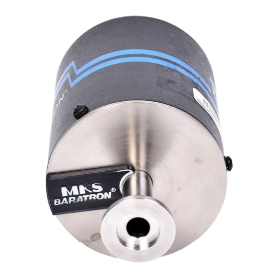
OPERATION General Theory of Operation SECTION 4 MAINTENANCE General Troubleshooting SECTION 1 GENERAL INFORMATION DESCRIPTION The MKS Type 107B Transducer is the result of over twenty five years experience with capacitance manometers and the addition of a new sensor design... -
Page 3: Specifications
When coupled with MKS Type 116 or 146 Power Supply/Readouts, the 107B can replace two or more pressure instruments in applications such as data logging or process control, where environmental and process conditions are particularly demanding. - Page 4 Environmental: Operating ambient Temperature: 15-40 ° C. Humidity: 0-95% non-condensing. * Accuracy is the system accuracy when used with either a 116 or 146 Power Supply/ Readout.
- Page 5 TABLE 1-1 Pressure Specification...
-
Page 6: Unpacking And Inspection
SECTION 2 INSTALLATION UNPACKING AND INSPECTION Reasonable care has been taken to pack the Type 107B in a manner that it reach you in perfect operating condition. However, upon receiving these units you should check for defects, cracks, broken connectors, etc. to be certain that damage has not occurred during shipment. -
Page 7: Cabling And Interconnections
CABLING Since each 107B transducer comes with its own linearity correction data stored in EEPROM memory on board, a 107B may be used with any 116 or 146 readout. The cable supplied with the 107B is a CB107-1 or CB107-2 which requires that two screws be tightened on each end. -
Page 8: Operation
Minimum resolvable readings are 1 milliTorr and the 107B's full scale is 1000 Torr. The variable capacitance sensor has rigidly attached electrodes located in an evacuated chamber behind the metal diaphragm. - Page 9 With the transducer held to zero pressure (high vacuum) the two capacitances will be equal and the bridge arrangement will have zero output. (For calibration purposes, at zero the 107B really develops between -50 millivolts and -125 millivolts output.) As the pressure increases, the sensor capacitance will increase and the bridge circuit will be unbalanced causing a DC voltage across the bridge.
- Page 10 Figure 3-1 107B Block Diagram Setting the output for a specific value is not needed since the transducer's complete output curve is described by the data stored in EEPROM on board the transducer. The circuitry needed to perform this task consists of a 5 volt...
-
Page 11: Maintenance
However, by monitoring and recording the 107B output voltage at zero pressure (and other pressures if available) as part of routine maintenance, these problems can be identified or anticipated. 107B output at zero pressure should normally be between -125 millivolts and -50 millivolts, although the transducer will operate satisfactorily with shifts of ±50 milli-volts outside of this range.
Need help?
Do you have a question about the 107B and is the answer not in the manual?
Questions and answers