Advertisement
Quick Links
DC MOTOR
2
click
1. Introduction
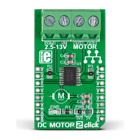
DC MOTOR 2 click carries the TB6593FNG
driver IC for direct current motors. With two
pairs of screw terminals (power supply and
outputs), the click board can drive motors
with voltages from 2.5 to 13V (output
current of up to 1.2 amps with peaks up to
3.2 amps). DC MOTOR 2 click communicates
with the target microcontroller through
mikroBUS
PWM, INT (here SLP), RST and CS
™
pins (here IN2 and IN1). The board can use
either a 3.3V or a 5V power supply.
2. Soldering the headers
Before using your click board
™
, make sure
to solder 1x8 male headers to both left and
right side of the board. Two 1x8 male headers
are included with the board in the package.
2
Turn the board upside down so that
the bottom side is facing you upwards.
Place shorter pins of the header into the
appropriate soldering pads.
1
3
Turn the board upward again. Make sure
to align the headers so that they are
perpendicular to the board, then solder the
pins carefully.
3. Plugging the board in
Once you have soldered the headers your
board is ready to be placed into the desired
mikroBUS
socket. Make sure to align the cut
™
in the lower-right part of the board with the
markings on the silkscreen at the mikroBUS
socket. If all the pins are aligned
correctly, push the board all the
way into the socket.
4. Essential features
The PWM signal drives the motor while the
IN1 and IN2 pins provide binary direction
signals that set the direction of the motor
(clockwise or counter clockwise), or apply
stop or short break functions. Stop mode cuts
off the power supply so the motor continues
spinning until it runs out of momentum.
Short break brings it to an abrupt stop (it
also blocks the rotor so it resists spinning
even when external momentum is applied).
The Standby is power saving, putting the
chip in sleep mode when in low logic level.
click
BOARD
™
www.mikroe.com
™
DC Motor 2 click manual
ver 1.00
0 1 0 0 0 0 0 0 8 1 4 0 2
Advertisement

Related Manuals for mikroElektronika DC MOTOR 2 click


Summary of Contents for mikroElektronika DC MOTOR 2 click
- Page 1 1. Introduction DC MOTOR 2 click carries the TB6593FNG 3. Plugging the board in click driver IC for direct current motors. With two pairs of screw terminals (power supply and...
- Page 2 WIDTH the present schematic are subject to change 17.5 HEIGHT* DC MOTOR 2 click features an SMD jumper at any time without notice. (zero ohm resistor) that let’s you switch 42.9 mm / 1690 mils between a 3.3V or a 5V power supply.
Need help?
Do you have a question about the DC MOTOR 2 click and is the answer not in the manual?
Questions and answers