
Related Manuals for mikroElektronika MINI-M0


Summary of Contents for mikroElektronika MINI-M0
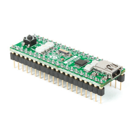
- Page 1 MINI-M0 ™ development board for STM32 The whole STM32 development board fitted in DIP40 form factor, containing high-performance STM32F051R8 ARM Cortex-M0 microcontroller. MINI...
- Page 2 TO OUR VALUED CUSTOMERS I want to express my thanks to you for being interested in our products and for having confidence in MikroElektronika. The primary aim of our company is to design and produce high quality electronic products and to constantly improve the performance thereof in order to better suit your needs.
-
Page 3: Table Of Contents
Introduction to MINI-M0 for STM32 Key features System Specification 1. Programming with mikroBootloader step 1 – Connecting MINI-M0 for STM32 step 2 – Browsing for .HEX file step 3 – Selecting .HEX file step 4 – Uploading .HEX file step 5 – Finish upload 2. -
Page 4: Introduction To Mini-M0 For Stm32
DATA LED If there is need for external programmers (mikroProg or ST- ™ LINK V2) attach it to MINI-M0 for STM32 via pads marked STAT LED with PA14 (TCK/SWC), PA13... -
Page 5: System Specification
System Specification power supply 3.3V via pads or 5V via USB power consumption depends on MCU state (max current into 3.3V pad is 300mA) board dimensions 50.8 x 17.78mm (2 x 0.7“) weight ~6g (0.013 lbs) Page 5... -
Page 6: Programming With Mikrobootloader
1. Programming with mikroBootloader mikroBootloader software You can program the microcontroller with bootloader which note is preprogrammed into the device by default. To transfer Before starting mikroBootloader software, connect MINI M0 for .HEX file from a PC to MCU you need bootloader software STM32 to a PC using a USB cable provided with the package (UART mikroBootloader) which can be downloaded from:... - Page 7 Identifying device COM port step 1 – Choosing COM port Figure 2-2: Identifying COM port Figure 2-3: Choosing COM port Device Manager Open window and expand Click the Change Settings button Ports section to see which COM port is assigned From the drop down list, select appropriate to MINI M0 for STM32 (in this case it is COM3) port...
-
Page 8: Step 2 - Browsing For .Hex File
step 2 - Establishing Connection step 3 - Browsing for .HEX file Figure 2-4: Connecting with mikroBootloader Figure 2-5: Browse for HEX Reset Browse for HEX Press the button on MINI M0 for STM32 board Click the button and from a and click the Connect button within 5s, otherwise the... -
Page 9: Step 3 - Selecting .Hex File
step 4 - Selecting .HEX file step 5 - Uploading .HEX file Figure 2-6: Locating and selecting .hex file Figure 2-7: Begin uploading Select .HEX file using open dialog window. To start .HEX file bootloding click the Begin uploading button Click the Open button... -
Page 10: Schematic
2. Schematic VDD-3.3V VDD-3.3V 10uF VCC-USB 287K 100nF 100nF 100nF 2.2uF EN ADJ AP7331-ADJ VDD-3.3V PC13 VDD-3.3V PC12 RST# VDD-3.3V VDD-3.3V RST# PB12 RESET 100nF 10pF VBAT PC13 32.768KHz PC13 OSC32_IN PA13 VDD-3.3V PC14 PA13 10pF OSC32_OUT PC15 PA12 OSC_IN PA11 OSC_OUT VDD-3.3V... -
Page 11: Pinout
3. Pinout Pin functions Pin functions SPI0-MISO nMCLR SPI0-MOSI SPI0 SPI0-SCK Analog I/O SPI0-SS PA14 TCK/SWC TMS/SWD PA13 INT0 SPI1-SS PB12 INT1 3.3V 3.3V Power supply INT2 3.3V Power supply 3.3V PB10 I2C-SCL PB11 I2C-SDA U0RX INT3 UART0 U0TX PWM0 PWM1 PB15 SPI1-MOSI... -
Page 12: Dimensions
4. Dimensions 50.8 2000 2.54 Legend mils Page 12... - Page 13 Notes: Page 13...
- Page 14 Notes: Page 14...
- Page 15 No part of this manual, including product and software described herein, may be reproduced, stored in a retrieval system, translated or transmitted in any form or by any means, without the prior written permission of MikroElektronika. The manual PDF edition can be printed for private or local use, but not for distribution.
- Page 16 If you are experiencing some problems with any of our products or just need additional information, please place your ticket at www.mikroe.com/support/ If you have any questions, comments or business proposals, MINI-M0 for STM32 ver. 1.00 do not hesitate to contact us at office@mikroe.com...
- Page 17 Mouser Electronics Authorized Distributor Click to View Pricing, Inventory, Delivery & Lifecycle Information: MikroElektronika MIKROE-1518...
Need help?
Do you have a question about the MINI-M0 and is the answer not in the manual?
Questions and answers