Table of Contents
Advertisement
Quick Links
Advertisement
Table of Contents

Related Manuals for mikroElektronika mikromedia+


Summary of Contents for mikroElektronika mikromedia+
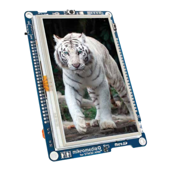
- Page 1 mikromedia+ for STM32 ARM ® Amazingly compact, all-on-single-pcb development board carring 4.3’’ TFT Touch Screen and lots of multimedia peripherals, all driven by powerful STM32F407ZG microcontroller from ARM Cortex -M4 family ® ™ Downloaded from DatasheetLib.com - datasheet search engine...
- Page 2 TO OUR VALUED CUSTOMERS I want to express my thanks to you for being interested in our products and for having confidence in MikroElektronika. The primary aim of our company is to design and produce high quality electronic products and to constantly improve the performance thereof in order to better suit your needs.
-
Page 3: Table Of Contents
Table of Contents Introduction to mikromedia+ for STM32 ARM 4. RTC Battery and Reset Button ® System Specification 5. Crystal oscillator and 2.048V reference Package Contains 6. MicroSD Card Slot 1. Power supply 7. Touch Screen 2. STM32F407ZG microcontroller 8. Audio Module Key microcontroller features 9. -
Page 4: Introduction To Mikromedia+ For Stm32 Arm
Introduction to mikromedia+ for STM32 ARM ® System Specification mikromedia+ for STM32 ARM is a compact development ® system with lots of on-board peripherals which allow development of devices with multimedia contents. The central power supply Cortex -M4 STM32F407ZG part of the system is a 32-bit ®... -
Page 5: Package Contains
PRODUCT DVD www.mikroe.com www.libstock.com Copyright ©2012 Mikroelektronika. All rights reserved. MikroElektronika, MikroElektronika logo and other MikroElektronika trademarks are the property of MikroElektronika. All other trademarks are the property of their respective owners. Unauthorised copying, hiring, renting, public performance and broadcasting of this DVD is strictly prohibited. -
Page 6: Power Supply
1. Power supply Figure 1-1: Figure 1-2: Figure 1-3: USB power supply Battery power supply Screw terminals power supply The mikromedia+ for STM32 ARM board can be powered in three different ways: via USB connector using MINI-B USB cable provided ®... - Page 7 VCC-3.3V VCC-5V VCC-3.3V USB-VBUS_ER VBUS_ER USB-PSW VCC-3.3V USB-VBUS_ER USB-VBUS USB-CONN VBUS USB-ID 1.5uH Vusb_OUT VCC-5V DC-VBUS# DC-VBUS# TPS2041B C138 PDTC114EU 100nF 10uF VOUT PWR-EN PGND VAUX 100K TPS63060 C139 C140 C141 USB-PSW 22uF B340A 22uF 22uF 22uF 100nF 10nF 100pF 10pF Vusb_IN VBUS...
-
Page 8: Stm32F407Zg Microcontroller
2. STM32F407ZG microcontroller The mikromedia+ for STM32 ARM development board ® comes with the 144-pin Cortex -M4 STM32F407ZG ® ™ microcontroller. This high-performance 32-bit microcontroller with its integrated modules and in combination with other on-board modules is ideal for multimedia applications. Key microcontroller features 210 DMIPS - Up to... -
Page 9: Programming The Microcontroller
3. Programming the microcontroller Figure 3-1: STM32F407ZG Cortex ® ™ Microcontroller The microcontroller can be programmed in two ways: Using USB mikroBootloader Using external mikroProg for STM32 or ST-LINK programmer ™ Page 9 Downloaded from DatasheetLib.com - datasheet search engine... -
Page 10: Programming With Mikrobootloader
Programming with mikroBootloader step 1 – Connecting mikromedia You can program the microcontroller with bootloader which is pre programmed into the device by default. To transfer .HEX file from a PC to MCU you need bootloader software (mikroBootloader HID) which can be downloaded from: http://www.mikroe.com/downloads/get/1976/mikro- media_plus_mikrobootloader_v210.zip After software is downloaded unzip it to desired location and... -
Page 11: Step 2 - Browsing For .Hex File
step 2 – Browsing for .HEX file step 3 – Selecting .HEX file Figure 3-3: Browse for HEX Figure 3-4: Selecting HEX Click the Browse for HEX button and from a Select .HEX file using open dialog window. pop-up window (Figure 3.4) choose the .HEX file Click the Open button. -
Page 12: Step 4 - Uploading .Hex File
step 4 – Uploading .HEX file Figure 3-5: Begin uploading Figure 3-6: Progress bar To start .HEX file uploading click the You can monitor .HEX file uploading via progress bar Begin uploading button. Page 12 Downloaded from DatasheetLib.com - datasheet search engine... -
Page 13: Step 5 - Finish Upload
step 5 – Finish upload Figure 3-7: Restarting MCU Figure 3-8: mikroBootloader ready for next job Click the button after uploading is finished. Board will automatically reset and after 5 seconds your new program will execute. Page 13 Downloaded from DatasheetLib.com - datasheet search engine... -
Page 14: Programming With Mikroprog ™ Programmer
Programming with mikroProg programmer ™ Figure 3-9: mikroProg ™ JTAG connector mikroProg for STM32 programmer mikroProg Suite for ARM software. The microcontroller can be programmed with external ™ ™ ® The external programmer is connected to the development system via JTAG connector, Figure 3-9. mikroProg is a fast USB 2.0 ™... - Page 15 VCC-3.3V TMS-SWDIO TCK-SWCLK VCC-3.3V VCC-3.3V RESET# Vbat_mcu JTAG R86 100K BAT1 3000TR C107 2.2uF OSC32_IN VCC-3.3V OSC32_OUT VCAP2 TMS-SWDIO PA13 PA12 32.768KHz VBAT PA11 C108 C109 PC13 PA10 OSC32_IN 10pF 10pF PC14 OSC32_OUT PC15 VCC-3.3V OSC_IN STM32F407ZG OSC_OUT 25MHz PF10 C110 C111 OSC_IN...
-
Page 16: Mikroprog Suite ™ For Arm ® Software
DVD://download/eng/software/development-tools/arm/stellaris/ mikroprog/mikroprog_suite_for_arm_v110.zip Copyright ©2012 Mikroelektronika. All rights reserved. MikroElektronika, MikroElektronika logo and other MikroElektronika trademarks are the property of MikroElektronika. All other trademarks are the property of their respective owners. Unauthorised copying, hiring, renting, public performance and broadcasting of this DVD is strictly prohibited. -
Page 17: Software Installation Wizard
Software installation wizard Start Installation Accept EULA and continue Install for all users Choose destination folder Installation in progress Finish installation Page 17 Downloaded from DatasheetLib.com - datasheet search engine... -
Page 18: Rtc Battery And Reset Button
4. RTC Battery and Reset Button Reset Button The board is equipped with reset button, which is located on the front side of the board. If you want to reset the circuit, press the reset button. It will generate low voltage level on the microcontroller reset pin (input). - Page 19 VCC-3.3V VCC-3.3V Vbat_mcu R86 100K BAT1 3000TR C107 2.2uF VCC-3.3V VCC-3.3V VCAP2 RESET# PA13 PA12 VBAT PA11 PC13 PA10 RESET PC14 100nF PC15 VCC-3.3V VCC-3.3V HDR2 RESET# STM32F407ZG PF10 PD15 PD14 RESET# NRST VCC-3.3V PD13 PD12 PD11 PD10 VSSA VREF+ VDDA PB15 PB14...
-
Page 20: Crystal Oscillator And 2.048V Reference
5. Crystal oscillator and 2.048V reference 25MHz The board is equipped with crystal oscillator (X5) circuit that provides external clock waveform to the microcontroller OSCO and OSCI pins. This base frequency is suitable for further clock multipliers and ideal for generation of necessary USB clock, which ensures proper operation of bootloader and your custom USB- 32.768... - Page 21 VCC-3.3V VCC-3.3V Vbat_mcu R86 100K BAT1 3000TR C107 2.2uF VCC-3.3V VCAP2 PA13 PA12 VBAT PA11 PC13 PA10 OSC32_IN PC14 OSC32_OUT PC15 32.768KHz C108 C109 10pF 10pF VCC-3.3V STM32F407ZG PF10 OSC_IN PD15 OSC_OUT PD14 NRST 25MHz PD13 C110 C111 VCC-3.3V PD12 22pF 22pF PD11...
-
Page 22: Microsd Card Slot
6. microSD Card Slot Board contains microSD card slot for using microSD cards in your projects. It enables you to store large amounts of data externally, thus saving microcontroller memory. microSD cards use Serial Peripheral Interface (SPI) for communication with the microcontroller. Ferrite and capcitor are provided to Figure 6-1: compensate the voltage and current glitch that can occur when pushing-in and pushing- microSD card slot... - Page 23 VCC-MMC SD-DAT2 DAT2 SD-DAT3 VCC-3.3V DAT3 SD-CMD Vbat_mcu +3.3V SD-CLK R86 100K BAT1 SD-DAT0 DAT0 3000TR SD-DAT1 DAT1 C107 SD-CD# 2.2uF VCAP2 PA13 PA12 VCC-3.3V VBAT PA11 PC13 PA10 OSC32_IN OSC32_IN PC14 OSC32_OUT OSC32_OUT PC15 SD-DAT1 SD-DAT0 32.768KHz C108 C109 10pF 10pF VCC-3.3V...
-
Page 24: Touch Screen
7. Touch Screen 4.3‘‘ The development system features a TFT 480x272 display covered with a resistive touch panel. Together they touch form a functional unit called a screen, Figure 7-1. It enables data to be entered and displayed at the same time. The TFT display is capable of showing graphics in 256K... - Page 25 TFT1 AT043B35-15I-10 VCC-3.3V VCC-1.2V VCC-3.3V Vbat_mcu R86 100K BAT1 3000TR C107 2.2uF OSC32_IN OSC32_OUT VDDD VCAP2 VDDIO PA13 PA12 32.768KHz VDDIO VDDD VBAT PA11 C108 C109 PC13 PA10 10pF 10pF OSC32_IN VDDD PC14 TFT-D0 OSC32_OUT PC15 TFT-D1 TFT-D2 OSC_IN TFT-D3 OSC_OUT TFT-D4 LCD-R2...
-
Page 26: Audio Module
8. Audio Module Figure 8-1: On-board VS1053 MP3 codec mikromedia+ for STM32 ARM features stereo audio codec ® VS1053. This module enables audio reproduction sound stereo headphones with microphone recording by using connected to the system via a 3.5mm connector CN2. All functions of this module controlled microcontroller over... - Page 27 LINE-OUT_L 10uF 3.3nF 100K VCC-3.3V VCC-1.8V VCC-3.3V Vbat_mcu LINE-OUT_R C132 R86 100K 10uF 10uF 100nF 100nF 100nF 100nF 100nF 100nF 100nF 100nF 100nF 100nF BAT1 3.3nF 100K 3000TR C107 2.2uF R17 1K C44 1uF VCC-3.3V 100nF VCAP2 MICP PA13 PA12 GBUF VBAT PA11...
-
Page 28: Usb Device Connection
9. USB DEVICE connection Figure 9-1: Connecting USB cable to MINI-B USB connector Cortex -M4 STM32F407ZG microcontroller has integrated USB module, which enables ® ™ you to implement USB communication functionality to your mikromedia board. Connection with target USB host is establish over MINI-B USB connector. - Page 29 Vusb_IN VCC-3.3V VCC-3.3V Vbat_mcu VBUS USB-D_N USB-D_P R86 100K USB-ID BAT1 3000TR C107 2.2uF USB MINIB USB-VBUS VCC-3.3V VCAP2 PA13 USB-D_P PA12 USB-D_N VBAT PA11 USB-ID PC13 PA10 OSC32_IN OSC32_IN USB-VBUS PC14 OSC32_OUT OSC32_OUT PC15 32.768KHz C108 C109 10pF 10pF VCC-3.3V STM32F407ZG PF10...
-
Page 30: Usb Host Connection
10. USB HOST connection Figure 10-1: Connecting USB cable to MINI-B USB connector via USB adapter mikromedia+ for STM32 ARM® can also be used as USB HOST which enables microcontroller to establish a connection with the target device (eg. USB keyboard, USB mouse, etc). The board provides necessary power supply to the target via TPS2041B IC. - Page 31 VCC-3.3V VCC-3.3V VCC-5V VCC-3.3V VCC-3.3V USB-VBUS_ER Vbat_mcu R86 100K Vusb_OUT BAT1 VCC-3.3V 3000TR TPS2041B C138 C107 100nF 2.2uF 10uF PMEG3010ER VCAP2 PA13 USB-PSW USB-D_P PA12 USB-D_N VBAT PA11 USB-ID PC13 PA10 OSC32_IN USB-VBUS PC14 VCC-3.3V OSC32_OUT PC15 VBUS USB-D_N USB-D_P USB-ID 10uF 10uF...
-
Page 32: Accelerometer
11. Accelerometer On board ADXL345 accelerometer is used to measure Figure 11-1: acceleration in three axis: x, y and z. The accelerometer Accelerometer function is defined by the user in the program loaded module into the microcontroller. Communication between the accelerometer and the microcontroller is performed via the interface. - Page 33 VCC-3.3V VCC-3.3V VCC-3.3V I2C1_SCL VCC-3.3V I2C1_SDA VCC-3.3V ACCEL-ADR Vbat_mcu R86 100K INT2 ACCEL-INT BAT1 INT1 3000TR VCC-3.3V I2C1_SCL C107 ADXL345 I2C1_SDA 2.2uF ACCEL-INT VCAP2 PA13 PA12 VBAT PA11 VCC-3.3V VCC-3.3V PC13 PA10 OSC32_IN OSC32_IN PC14 OSC32_OUT OSC32_OUT PC15 VCC-3.3V C133 100nF 100nF 32.768KHz...
-
Page 34: Flash Memory
12. Flash Memory Figure 12-1: Since multimedia applications are getting increasingly Flash memory demanding, it is necessary to provide additional module memory space to be used for storing more data. The flash memory module enables the microcontroller to use additional 8Mbit flash memory. - Page 35 VCC-3.3V Vbat_mcu VCC-3.3V VCC-3.3V VCC-3.3V R86 100K C128 BAT1 3000TR C107 100nF 2.2uF SF_CS SPI2_MISO HOLD SPI2_SCK R100 27 SPI2_MOSI VCAP2 M25P80 PA13 PA12 VBAT PA11 VCC-3.3V PC13 PA10 OSC32_IN PC14 OSC32_OUT PC15 OSC32_IN OSC32_OUT 32.768KHz C108 C109 STM32F407ZG 10pF 10pF VCC-3.3V PF10...
-
Page 36: Rf Transceiver
13. RF Transceiver Figure 13-1: Figure 13-2: RF transceiver antenna RF transceiver module RF transceiver 2.4GHz chip antenna. It is suitable for wireless operation mikromedia+ for STM32 ARM board features chip with ® in the world wide ISM frequency band at 2.400 - 2.4835 GHz with air data rate up to 2Mbps. RF transceiver module is connected to the microcontroller via the Serial Peripheral Interface (SPI). - Page 37 VCC-3.3V OSC32_IN OSC32_OUT VCC-3.3V Vbat_mcu 32.768KHz C109 C108 R86 100K 10pF 10pF BAT1 3000TR C107 2.2uF OSC_IN VCC-3.3V OSC_OUT 25MHz VCAP2 C111 C110 PA13 22pF 22pF PA12 VBAT PA11 PC13 PA10 OSC32_IN PC14 OSC32_OUT PC15 VCC-3.3V VCC-3.3V VCC-RF FERRITE STM32F407ZG 10uF 100nF 100nF...
-
Page 38: Ethernet Transceiver
14. Eternet Transceiver 14. Ethernet transceiver Figure 14-1: Ethernet transceiver module The development system features a Ethernet transceiver module ideal for local area networking (LAN). Communication over Ethernet is based on data packets called frames. Each frame contains source and destination addresses and error-cheching data so that damaged data can be detected and re-transmitted. - Page 39 VCC-3.3V C135 VCC-3.3V 12K1 100nF VCC-3.3V Vbat_mcu R86 100K LINK LAN-TXD1 BAT1 VDD2A TXD1 LAN-LED2 LAN-TXD0 3000TR LED2 TXD0 LAN-LED1 LAN-TXEN C107 LED1 TXEN LAN8720A LAN-RST# 2.2uF XTAL2 nRST LAN-CLK LAN-INT# XTAL1 nINT LAN-MDC ACTIVE VDDCR VCAP2 VCC-3.3V PA13 PA12 C136 C137 VBAT...
-
Page 40: Buzzer
15. Buzzer The board is also equipped with piezo buzzer. It is an electric component which can be used to create sound waves when provided with electrical signal. Microcontroller can create Figure 15-1: sound by generating a PWM signal. Frequency Buzzer module of the signal determines the pitch of the sound and duty cycle of the signal can be used to... - Page 41 VCC-5V VCC-3.3V Vbat_mcu BUZZER R86 100K BAT1 3000TR C107 PDTC114EU 2.2uF BUZZER VCAP2 PA13 PA12 VBAT PA11 PC13 PA10 OSC32_IN OSC32_IN PC14 OSC32_OUT OSC32_OUT PC15 32.768KHz C108 C109 10pF 10pF VCC-3.3V STM32F407ZG PF10 OSC_IN OSC_IN PD15 OSC_OUT OSC_OUT PD14 NRST 25MHz PD13 C110...
-
Page 42: Other Modules
16. Other modules The board also contains additional peripherals that can be very useful, such as PIN photodiode, IR receiver, RGB led diode and analog temperature sensor. PIN photodiode is a type of photo detector capable of converting light into the voltage with high sensitivity and speed of response. - Page 43 27K4 100K VCC-5V VCC-3.3V U17A LM358 AN-PD 150K VCC-3.3V PDTC114EU Vbat_mcu U17B LM358 C149 LED_R PD15 R86 100K 100nF BAT1 3000TR C107 2.2uF VCC-3.3V VCC-3.3V C103 100nF VCC-5V VCAP2 PA13 PA12 VBAT PA11 PC13 PA10 OSC32_IN PC14 OSC32_IN OSC32_OUT PDTC114EU PC15 OSC32_OUT LED_G...
-
Page 44: Pads
17. Pads Interrupt UART Analog lines 5V pwr. Reset pin Ground 3.3V 3.3V pwr. Audio out Audio in Analog lines PD12 PD13 PD14 GPIO PWM lines PC13 PD15 PB12 PB13 SPI2 lines PB14 PB15 Interrupt lines CAN lines PA15 I2C2 lines SPI1 lines UART2 lines LAN-TX... - Page 45 VCC-3.3V VCC-3.3V VCC-3.3V Vbat_mcu R86 100K VCC-3.3V BAT1 3000TR VCC-3.3V C107 VCC-5V 2.2uF HDR2 HDR1 HDR-RST# HDR-INT2 HDR-INT3 HDR-LN_OUT_L HDR-GPIO1 HDR-AN0 VCAP2 HDR-LN_OUT_R HDR-PWM4 HDR-AN1 PA13 HDR-LN_IN_L HDR-PWM5 HDR-AN2 PA12 HDR-LN_IN_R HDR-AN3 VBAT PA11 HDR-PWM0 HDR-GPIO2 HDR-AN4 PC13 PA10 HDR-PWM1 OSC32_IN HDR-AN5 PC14...
-
Page 46: Mikromedia+ Accessories
mikromedia+ for STM32 shield We have prepared an extension board pin-compatible with your mikromedia+ board, which enables you to easily expand your basic board functionality. It is mikromedia+ SHIELD for called STM32 ARM . The shield contains ® FTDI USB-UART chip with USB MINI-B connector, transceiver with CAN screw... - Page 47 VCC-3.3V VCC-5V VCC-3.3V VCC-5V VCC-3.3V VCC-5V VCC-3.3V VCC-5V PA4/AN1 PD12/PWM1 PB0/AN2 PD13/PWM2 PB1/AN3 PD14/PWM3 PC0/AN4 PD15/PWM4 PE1/INT2 PB12 PE2/INT3 PE0/INT1 PE3/INT4 PA3/UART1-RX PC13 PA3/UART1-RX PA15 PA3/UART1-RX PA3/UART1-RX PA5/SPI-SCK PD5/UART1-TX PA5/SPI-SCK PD5/UART1-TX PA5/SPI-SCK PD5/UART1-TX PA5/SPI-SCK PD5/UART1-TX PA6/SPI-MISO PF1/I2C-SCL PA6/SPI-MISO PF1/I2C-SCL PA6/SPI-MISO PF1/I2C-SCL PA6/SPI-MISO PF1/I2C-SCL...
-
Page 48: What's Next
GUI. It will automatically create necessary code which is compatible with mikroElektronika compilers. Visual TFT is rich with examples, which are an excellent starting point for your future projects. Just load the example, read well commented code, and see how it works on hardware. - Page 49 Notes: Page 49 Downloaded from DatasheetLib.com - datasheet search engine...
- Page 50 Notes: Page 50 Downloaded from DatasheetLib.com - datasheet search engine...
- Page 51 No part of this manual, including product and software described herein, may be reproduced, stored in a retrieval system, translated or transmitted in any form or by any means, without the prior written permission of MikroElektronika. The manual PDF edition can be printed for private or local use, but not for distribution.
- Page 52 If you want to learn more about our products, please visit our website at www.mikroe.com If you are experiencing some problems with any of our products or just need additional information, please place your ticket at www.mikroe.com/esupport If you have any questions, comments or business proposals, mikromedia Plus for STM32 ARM ®...
Need help?
Do you have a question about the mikromedia+ and is the answer not in the manual?
Questions and answers