Advertisement
Quick Links
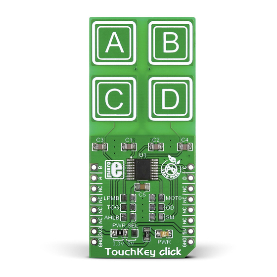
TouchKey
click
1. Introduction
TouchKey click has four capacitive pads
powered by TTP224, a touchpad detector IC.
The board outputs an interrupt singnal for
each pad: OUTA, OUTB, OUTC and OUTD (in
place of default mikroBUS
RST, AN, PWM
™
and INT pins, respectivelly, respectively).
TouchKey click is designed to work either
with a 3.3V or 5V power supply.
2. Soldering the headers
Before using your click board
™
, make sure
to solder 1x8 male headers to both left and
right side of the board. Two 1x8 male headers
are included with the board in the package.
2
Turn the board upside down so that
the bottom side is facing you upwards.
Place shorter pins of the header into the
appropriate soldering pads.
1
3
Turn the board upward again. Make sure
to align the headers so that they are
perpendicular to the board, then solder the
pins carefully.
3. Plugging the board in
Once you have soldered the headers your
board is ready to be placed into the desired
mikroBUS
socket. Make sure to align the
™
cut in the lower-right part of the board with
the markings on the silkscreen at the
mikroBUS
socket. If all the
™
pins are aligned correctly,
push the board all the way
into the socket.
4. Essential features
TouchKey
click
offers
a
replacement
for standard mechanical switches and
buttons. It can be used in a wide variety of
applications and under diverse conditions,
but perhaps the most interesting feature is
that the keys can be toggled even through a
layer of glass, paper, or similar non-isolating
materials. The response time is just 100mS
at fast mode and 200mS at low power mode.
click
BOARD
™
www.mikroe.com
TouchKey click manual
ver 1.00
0 1 0 0 0 0 0 0 8 0 2 7 6
Advertisement

Related Manuals for mikroElektronika TouchKey click


Summary of Contents for mikroElektronika TouchKey click
- Page 1 1.00 and INT pins, respectivelly, respectively). pins are aligned correctly, TouchKey click is designed to work either push the board all the way 0 1 0 0 0 0 0 0 8 0 2 7 6 with a 3.3V or 5V power supply.
- Page 2 HEIGHT* CMOS active Open drain at any time without notice. Multi-key Single-key 57.15 / 2250 mils TouchKey click has three jumpers for putting Copyright © 2015 MikroElektronika. * without headers the TTP224 IC into different operating modes. All rights reserved.
Need help?
Do you have a question about the TouchKey click and is the answer not in the manual?
Questions and answers