Table of Contents
Advertisement
Quick Links
Advertisement
Table of Contents

Related Manuals for Supermicro SuperServer 5019A-FTN10P


Summary of Contents for Supermicro SuperServer 5019A-FTN10P
- Page 1 SuperServer ® 5019A-FTN10P USER'S MANUAL Revision 1.0...
- Page 2 State of California, USA. The State of California, County of Santa Clara shall be the exclusive venue for the resolution of any such disputes. Supermicro's total liability for all claims will not exceed the price paid for the hardware product.
- Page 3 About this Manual This manual is written for professional system integrators and PC technicians. It provides information for the installation and use of the SuperServer 5019A-FTN10P. Installation and maintenance should be performed by experienced technicians only. Please refer to the 5019A-FTN10P server specifications page on our website for updates on supported memory, processors, and operating systems (http://www.supermicro.com).
-
Page 4: Table Of Contents
Preface Contents Chapter 1 Introduction 1.1 Overview ..........................8 1.2 Unpacking the System ......................8 1.3 System Features ........................9 1.4 Server Chassis Features ....................10 Control Panel ........................10 Front Features ........................11 1.5 Motherboard Layout ......................12 Quick Reference Table ......................13 Chapter 2 Server Installation 2.1 Overview ..........................16 2.2 Preparing for Setup ......................16 Choosing a Setup Location ....................16... - Page 5 SuperServer 5019A-FTN10P User's Manual Hard Drives ........................25 Installing 3.5" Fixed Hard Drives ...................26 Installing 2.5" Fixed Hard Drives ...................27 Expansion Card .........................28 System Cooling .........................29 System Fan Failure .......................29 Checking the Chassis Airflow ..................30 Power Supply ........................30 Chapter 4 Motherboard Connections 4.1 Power Connections ......................32...
- Page 6 Preface Appendix A BIOS Codes Appendix B UEFI BIOS Recovery Appendix C System Specifications Appendix D Standardized Warning Statements for AC Systems Appendix E Standardized Warning Statements (Traditional Chinese) Appendix F Dual Boot Block...
- Page 7 SuperServer 5019A-FTN10P User's Manual Contacting Supermicro Headquarters Address: Super Micro Computer, Inc. 980 Rock Ave. San Jose, CA 95131 U.S.A. Tel: +1 (408) 503-8000 Fax: +1 (408) 503-8008 Email: marketing@supermicro.com (General Information) support@supermicro.com (Technical Support) Website: www.supermicro.com Europe Address: Super Micro Computer B.V.
-
Page 8: Overview
*Note: Required for configurations with four 2.5" HDDs. 1.2 Unpacking the System Inspect the box that the SuperServer 5019A-FTN10P was shipped in and note if it was damaged in any way. If any equipment appears damaged, file a damage claim with the carrier who delivered it. -
Page 9: System Features
Chapter 1: Introduction 1.3 System Features The following table provides an overview of the main features of the 5019A-FTN10P. Refer to Appendix C for additional specifications. System Features Motherboard A2SDV-8C-LN10PF Chassis SC505-203B Intel Atom processor C3758 Socket Type FCBGA1310 Memory Supports up to 256GB of ECC RDIMM or 64GB of ECC/non-ECC UDIMM DDR4 memory in four DIMM slots Chipset Intel Atom SoC chipset... -
Page 10: Server Chassis Features
SuperServer 5019A-FTN10P User's Manual 1.4 Server Chassis Features Control Panel The switches and LEDs located on the control panel are described below. The control panel is located next to the left handle of the chassis. See Chapter 4 for details on the control panel connections. -
Page 11: Front Features
Chapter 1: Introduction Information LED Status Description Continuously on and An overheat condition has occurred (possibly caused by cable congestion). Blinking red (1Hz) Fan failure. Check for an inoperative fan. Blinking red (0.25Hz) Power supply failure. Local UID is active. Use this function to identify Solid blue the server in a rack mount environment. -
Page 12: Motherboard Layout
SuperServer 5019A-FTN10P User's Manual 1.5 Motherboard Layout Below is a layout of the A2SDV-8C-LN10PF with jumper, connector, and LED locations shown. See the table on the following page for descriptions. For detailed descriptions, pinout information, and jumper settings, refer to Chapter 4. -
Page 13: Quick Reference Table
Chapter 1: Introduction Quick Reference Table Jumper Description Default Setting JBR1 BIOS Recovery Pins 1-2 (Normal) JBT1 CMOS Clear Open (Normal) C1, JI SMB to PCI-E Slots Enable/Disable Pins 2-3 (Disabled) JPG1 Onboard VGA Enable/Disable Pins 1-2 (Enabled) JPL1 LAN1 SFP Port Enable/Disable Pins 1-2 (Enabled) JPL2 LAN2 SFP Port Enable/Disable... - Page 14 SuperServer 5019A-FTN10P User's Manual Connector Description Power Supply SMBus I C Header JPH1 4-pin Power Connector for HDD use JPW1 24-pin ATX Power Connector JPV1 4-pin 12V DC Power Connector (To provide alternative power for a special enclosure when the 24-pin ATX power is not in use.)
- Page 15 Chapter 1: Introduction CPLD SMBUS2 LCMXO2-1200HC AST2400 COM1 HEADER UART1 FAN X5 TACHOMETER RTL8211F RJ45 RGMII2 GIGALAN TPM Header SVID VR13 HSIO[14] , PCIE X1 USB 2.0 [0] PCIE X4 SLOT 6 (OPTION) DDR4 (CHA) Intel DIMMA1,A2 PCIe 3.0_x4 2400MHz HSIO[3:0] , PCIE x4 PCIE X4 SLOT 7 FCBGA1310...
-
Page 16: Chapter 2 Server Installation
SuperServer 5019A-FTN10P User's Manual Chapter 2 Server Installation 2.1 Overview This chapter provides advice and instructions for mounting your system in a server rack. If your system is not already fully integrated with processors, system memory, etc., refer to Chapter 4 for details on installing those components. -
Page 17: Server Precautions
Chapter 2: Server Installation • In single-rack installations, stabilizers should be attached to the rack. In multi-rack instal- lations, the racks should be coupled together. • Always verify that the rack is stable before extending a server or other component from the rack. -
Page 18: Mechanical Loading
SuperServer 5019A-FTN10P User's Manual Mechanical Loading Equipment should be mounted into a rack so that a hazardous condition does not arise due to uneven mechanical loading. Circuit Overloading Consideration should be given to the connection of the equipment to the power supply circuitry and the effect that any possible overloading of circuits might have on overcurrent protection and power supply wiring. -
Page 19: Installing The System Into A Rack
Chapter 2: Server Installation 2.3 Installing the System into a Rack This section provides information on installing the 505-203B chassis into a rack unit. Due to the variety of rack units on the market, the assembly procedure might differ slightly. Also refer to the installation instructions that came with the rack unit you are using. -
Page 20: Chapter 3 Component Installation And Maintenance
SuperServer 5019A-FTN10P User's Manual Chapter 3 Component Installation and Maintenance This chapter provides instructions on installing and replacing main system components. To prevent compatibility issues, only use components that match the specifications and part numbers given. Remove power from the system and remove the top cover before installing or replacing components. - Page 21 Chapter 3: Component Installation and Maintenance Figure 3-1. Removing the Chassis Cover...
-
Page 22: Motherboard Components
SuperServer 5019A-FTN10P User's Manual 3.3 Motherboard Components Installing Memory Memory Support The A2SDV-8C-LN10PF supports up to 256GB of ECC RDIMM or 64GB of Non-EC/ECC UDIMM DDR4 memory in four DIMM slots. Refer to the table below for additional memory information. -
Page 23: Dimm Installation
Press both ends straight down into the memory slot. Notches Release Tabs Figure 3-3. Installing DIMMs Note: Visit the product page on the Supermicro website for possible updates to memory support (www.supermicro.com). -
Page 24: Motherboard Battery
SuperServer 5019A-FTN10P User's Manual Motherboard Battery The motherboard uses non-volatile memory to retain system information when system power is removed. This memory is powered by a lithium battery residing on the motherboard. Replacing the Battery Begin by removing power from the system as described in Section 3.1 and removing the cover as described in Section 3.2. -
Page 25: Chassis Components
Chapter 3: Component Installation and Maintenance 3.4 Chassis Components Hard Drives The chassis supports up to two 3.5" or four 2.5" HDDs, and one PCI-E expansion card. The following configurations are supported: • One 3.5" HDD and a low-profile PCI-E expansion card. •... -
Page 26: Installing 3.5" Fixed Hard Drives
SuperServer 5019A-FTN10P User's Manual Installing 3.5" Fixed Hard Drives You can install one 3.5" HDD and a PCI-E expansion card, or you can install two 3.5" HDDs and no expansion card. Installing 3.5" Hard Drives Begin by removing power from the system as described in Section 3.1 and removing the cover as described in Section 3.2. -
Page 27: Installing 2.5" Fixed Hard Drives
Chapter 3: Component Installation and Maintenance Installing 2.5" Fixed Hard Drives You can install between one and four 2.5" HDDs in various configurations. If two or fewer 2.5" HDDs are installed, you can also add a full-height, half-length PCI-E expansion card. If you want to install four 2.5"... -
Page 28: Expansion Card
SuperServer 5019A-FTN10P User's Manual Figure 3-8. Four 2.5" HDDs in Two Brackets, No Expansion Card Expansion Card The chassis supports one PCI-E expansion card installed with one 3.5" or two 2.5" HDDs. Refer to the supported configurations list in Section 3.4. -
Page 29: System Cooling
1. Disconnect the fan power cable from the motherboard and remove the broken fan. 2. Replace the failed fan with an identical 4028mm 13K RPM 4-pin PWM fan (available from Supermicro). 3. Position the new fan into the space vacated by the failed fan previously removed. An audible click indicates that the fan is fully installed. -
Page 30: Checking The Chassis Airflow
- 240V input voltage. If the power supply module fails, the system shuts down and you must replace the module. Replacement units can be ordered directly from Supermicro. Replacing the Power Supply Begin by removing power from the system as described in Section 3.1 (even if the server is offline) and removing the cover as described in Section 3.2. - Page 31 Chapter 3: Component Installation and Maintenance Mounting Through-Holes Power Supply Module Rear Mounting Screws Insert Bottom Mounting Screws from Underside Figure 3-11. Replacing the Power Supply...
-
Page 32: Power Connections
SuperServer 5019A-FTN10P User's Manual Chapter 4 Motherboard Connections This section describes the connections on the motherboard and provides pinout definitions. Depending on how the system is configured, not all connections are required. The LEDs on the motherboard are also described here. A motherboard layout indicating component locations can be found in Chapter 1. - Page 33 Chapter 4: Motherboard Connections 12V DC Power Connector The 4-pin (JPV1) connector is used to provide alternative power for a special enclosure when JTPM1 the 24-pin ATX power is not in use. JTGLED1 +12V 4-pin Power Pin Definitions JPV1 Pin# Definition JUIDB JWD1...
-
Page 34: Headers And Connectors
SuperServer 5019A-FTN10P User's Manual 4.2 Headers and Connectors Fan Headers The A2SDV-8C-LN10PF has three 4-pin fan headers (FAN1-3). These headers are backward compatible with the traditional 3-pin fans. However, fan speed control is available for 4-pin fans only by Thermal Management via the IPMI 2.0 interface. Refer to the table below for pin definitions. - Page 35 Chapter 4: Motherboard Connections General Purpose I/O Header JGP1 is a 10-pin general purpose I/O header. Each pin can be configured to be an input or output pin. The GPIO is controlled via the PCA9554 8-bit GPIO expansion. The base address is 0xF040(D31:F4).
- Page 36 SuperServer 5019A-FTN10P User's Manual BMC External I2C Header A System Management Bus header for IPMI 2.0 is located at JIPMB1. Connect the appropriate cable here to use the IPMB I C connection on your system. Refer to the table below for pin definitions.
- Page 37 Chapter 4: Motherboard Connections SATA Ports Five SATA 3.0 ports (I-SATA0/1/2/3/4) are available. SATA 3.0 Port Pin Definitions Pin# Signal Ground SATA_TXP SATA_TXN Ground SATA_RXN SATA_RXP Ground M.2 B-Key JMD1 is a B-key connector supporting a PCI-E 3.0 x2/SATA/USB device in 3042 or 2280 lengths.
- Page 38 Front RJ45 Link and Activity LED Header JFPCLED1 is the 1GbE RJ45 link and activity LED header. Attach a cable from this header to the Supermicro LED board (Part Number: FPB-FPE300-LED10) to display the status of the RJ45 LAN link and activity LED.
-
Page 39: Control Panel
JF1 contains header pins for various buttons and indicators that are normally located on a control panel at the front of the chassis. These connectors are designed specifically for use with Supermicro chassis. See the figure below for the descriptions of the front control panel buttons and LED indicators. - Page 40 SuperServer 5019A-FTN10P User's Manual Power Fail LED Connect an LED cable to Power Fail connections on pins 5 and 6 of JF1 to provide warnings for a power failure. Refer to the table below for pin definitions. Power Indicator Status...
- Page 41 Chapter 4: Motherboard Connections Power LED The Power LED connection is located on pins 15 and 16 of JF1. Refer to the table below for pin definitions. Power LED Pin Definitions (JF1) Pin# Definition +3.3V PWR LED NMI Button The non-maskable interrupt button header is located on pins 19 and 20 of JF1. Refer to the table below for pin definitions.
-
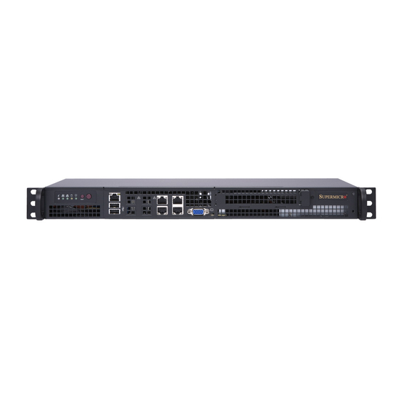
Page 42: Ports
SuperServer 5019A-FTN10P User's Manual 4.3 Ports Figure 4-2. I/O Ports Rear I/O Ports Description Description IPMI LAN LAN8 USB1 LAN7 USB0 LAN10 LAN4 LAN9 LAN3 LAN2 LAN6 LAN1 LAN5 VGA Port A VGA port is located on the I/O back panel. Use this port to connect to a compatible VGA display. - Page 43 Note: UID can also be triggered via IPMI on the motherboard. For more information on IPMI, please refer to the IPMI User's Guide posted on our website at https://www.supermicro.com/ support/manuals/. UID Button...
-
Page 44: Jumpers
SuperServer 5019A-FTN10P User's Manual 4.4 Jumpers Explanation of Jumpers To modify the operation of the motherboard, jumpers can be used to choose between optional settings. Jumpers create shorts between two pins to change the function of the connector. Pin 1 is identified with a square solder pad on the printed circuit board. See the diagram below for an example of jumping pins 1 and 2. - Page 45 Chapter 4: Motherboard Connections LAN Port Enable/Disable JPL1 Use JPL1 to enable/disable LAN1 SFP port. JPL2 Use JPL1 to enable/disable LAN2 SFP port. JPL3 Use JPL3 to enable/disable LAN3-6 RJ45 ports. JPL4 Use JPL4 to enable/disable LAN7-10 RJ45 ports. LAN Enable/Disable Jumper Settings Jumper Setting Definition...
- Page 46 SuperServer 5019A-FTN10P User's Manual Manufacturing Mode Select Close pins 2-3 of jumper JPME2 to bypass SPI flash security and force the system to operate in the manufacturing mode, which will allow the user to flash the system firmware from a host server for system setting modifications.
-
Page 47: Led Indicators
Chapter 4: Motherboard Connections 4.5 LED Indicators LAN LEDs Eight RJ45 LAN ports and two SFP LAN ports are located on the I/O back panel. Each Ethernet LAN port has two LEDs. One LED indicates activity, while the other Link LED may be green, amber, or off to indicate the speed of the connection. -
Page 48: Chapter 5 Software
USB/SATA DVD drive, or a USB flash drive, or the IPMI KVM console. 2. Retrieve the proper RST/RSTe driver. Go to the Supermicro web page for your motherboard and click on "Download the Latest Drivers and Utilities", select the proper driver, and copy it to a USB flash drive. - Page 49 Chapter 5: Software 4. During Windows Setup, continue to the dialog where you select the drives on which to install Windows. If the disk you want to use is not listed, click on “Load driver” link at the bottom left corner. Figure 5-2.
-
Page 50: Driver Installation
The Supermicro website contains drivers and utilities for your system at https://www. supermicro.com/wftp/driver. Some of these must be installed, such as the chipset driver. After accessing the website, go into the CDR_Images (in the parent directory of the above link) and locate the ISO file for your motherboard. Download this file to to a USB flash drive or a DVD. -
Page 51: Superdoctor ® 5
5.3 SuperDoctor ® The Supermicro SuperDoctor 5 is a program that functions in a command-line or web-based interface for Windows and Linux operating systems. The program monitors such system health information as CPU temperature, system voltages, system power consumption, fan speed, and provides alerts via email or Simple Network Management Protocol (SNMP). -
Page 52: Ipmi
SuperServer 5019A-FTN10P User's Manual 5.4 IPMI The A2SDV-8C-LN10PF supports the Intelligent Platform Management Interface (IPMI). IPMI is used to provide remote access, monitoring and management. There are several BIOS settings that are related to IPMI. For general documentation and information on IPMI, please visit our website at:... -
Page 53: Chapter 6 Uefi Bios
Chapter 6: UEFI BIOS Chapter 6 UEFI BIOS 6.1 Introduction This chapter describes the AMIBIOS™ Setup utility for the motherboard. The BIOS is stored on a chip and can be easily upgraded using a flash program. Note: Due to periodic changes to the BIOS, some settings may have been added or deleted and might not yet be recorded in this manual. -
Page 54: Main Setup
SuperServer 5019A-FTN10P User's Manual 6.2 Main Setup When you first enter the AMI BIOS setup utility, you will enter the Main setup screen. You can always return to the Main setup screen by selecting the Main tab on the top of the screen. - Page 55 Chapter 6: UEFI BIOS Memory Information Total Memory This feature displays the total size of memory available in the system. Memory Speed This feature displays the default speed of the memory modules installed in the system.
-
Page 56: Advanced Setup Configurations
SuperServer 5019A-FTN10P User's Manual 6.3 Advanced Setup Configurations Use this menu to configure Advanced settings. Warning: Take caution when changing the Advanced settings. An incorrect value, a very high DRAM frequency or an incorrect BIOS timing setting may cause the system to malfunction. - Page 57 Chapter 6: UEFI BIOS Watch Dog Function If enabled, the Watch Dog timer will allow the system to reboot when it is inactive for more than five minutes. The options are Disabled and Enabled. Power Button Function This feature controls how the system shuts down when the power button is pressed. Select 4 Seconds Override for the user to power off the system after pressing and holding the power button for four seconds or longer.
- Page 58 SuperServer 5019A-FTN10P User's Manual Select Enable to activate TM1 support for system thermal monitoring. TM1 allows the CPU to regulate its power consumption based upon the modulation of the CPU Internal clock when the CPU temperature reaches a pre-defined overheating threshold. The options are Disable and Enable.
- Page 59 Chapter 6: UEFI BIOS L2 Prefetcher If enabled, the hardware prefetcher will prefetch streams of data and instructions from the main memory to the L2 cache to improve CPU performance. The options are Enable and Disable. ACPI 3.0 T-States Select Enable to support ACPI (Advanced Configuration and Power Interface) 3.0 T-States to determine how the processor will report to the operating system during CPU-Throttling states.
- Page 60 SuperServer 5019A-FTN10P User's Manual Lock PACKAGE_RAPL_LIMIT Use this feature to lock the MSR 0x610 bit. The options are Disable and Enable. *If the feature above is set to Disable, the next three features will be available for configuration: PL1 Time Window Use this feature to define the Running Average Power Limit (RAPL) time window 1 in miliseconds.
- Page 61 Chapter 6: UEFI BIOS VT-d Interrupt remapping Use this feature to enable Interrupt Remapping support, which detects and controls external interrupt requests. The options are Disabled and Enabled. Fast Boot Use this feature to enable or disable fast path through the memory reference code. The options are Disabled and Enabled.
- Page 62 SuperServer 5019A-FTN10P User's Manual Demand Scrub Enable Demand Scrubbing is a process that allows the CPU to correct correctable memory errors found in a memory module. When the CPU or I/O issues a demand-read command, and the read data from memory turns out to be a correctable error, the error is corrected and sent to the requestor (the original source).
- Page 63 Chapter 6: UEFI BIOS South Bridge Configuration South Bridge Configuration • USB Module Version • USB Controllers: • USB Devices: Legacy USB Support Select Enabled to support onboard legacy USB devices. Select Auto to disable legacy support if there are no legacy USB devices present. Select Disable to have all USB devices available for EFI applications only.
- Page 64 SuperServer 5019A-FTN10P User's Manual SATA Configuration SATA0 SATA 0 Enable controller This item enables or disables the onboard SATA controller supported by the processor. The options are Enabled and Disabled. SATA 0 ALPM When this feature is set to Enabled, the SATA AHCI controller manages the power usage of the SATA link.
- Page 65 Chapter 6: UEFI BIOS SATA1 SATA 1 Enable controller This item enables or disables the onboard SATA controller supported by the processor. The options are Enabled and Disabled. SATA 1 ALPM When this feature is set to Enabled, the SATA AHCI controller manages the power usage of the SATA link.
- Page 66 SuperServer 5019A-FTN10P User's Manual Intel Server Platform Services General ME Configuration • Operational Firmware Version • ME Firmware Type • Backup Firmware Version • Recovery Firmware Version • ME Firmware Features • ME Firmware Status #1 • ME Firmware Status #2 •...
- Page 67 Chapter 6: UEFI BIOS Maximum Read Request Select Auto for the system BIOS to automatically set the maximum size for a read request for a PCI-E device to enhance system performance. The options are Auto, 128 Bytes, 256 Bytes, 512 Bytes, 1024 Bytes, 2048 Bytes, and 4096 Bytes. ASPM Support Use this item to set the Active State Power Management (ASPM) level for a PCI-E device.
- Page 68 SuperServer 5019A-FTN10P User's Manual *If "Network Stack" is set to Enabled, the next four features will be available for configuration: Ipv4 PXE Support Use this feature to enable Ipv4 PXE Boot Support. If this feature is disabled, it will not create the Ipv4 PXE Boot option.
- Page 69 Chapter 6: UEFI BIOS Serial Port Console Redirection COM 1 Console Redirection Select Enabled to enable COM Port 1 for Console Redirection, which will allow a client machine to be connected to a host machine at a remote site for networking. The options are Enabled and Disabled.
- Page 70 SuperServer 5019A-FTN10P User's Manual COM1 Flow Control Use this item to set the flow control for Console Redirection to prevent data loss caused by buffer overflow. Send a "Stop" signal to stop sending data when the receiving buffer is full. Send a "Start" signal to start sending data when the receiving buffer is empty. The options are None and Hardware RTS/CTS.
- Page 71 Chapter 6: UEFI BIOS SOL Bits per second Use this feature to set the transmission speed for a serial port used in Console Redirection. Make sure that the same speed is used in the host computer and the client computer. A lower transmission speed may be required for long and busy lines.
- Page 72 SuperServer 5019A-FTN10P User's Manual Serial Port for Out-of-Band Management/Windows Emergency Management Services (EMS) Use the features in this submenu to configure Console Redirection settings to support Out- of-Band Serial Port management. EMS (Emergency Management Services) Console Redirection Select Enabled to use a COM port selected by the user for EMS Console Redirection. The options are Disabled and Enabled.
- Page 73 Chapter 6: UEFI BIOS Data Bits Parity Stop Bits ACPI Settings ACPI Settings WHEA Support Select Enabled to support the Windows Hardware Error Architecture (WHEA) platform and provide a common infrastructure for the system to handle hardware errors within the Windows OS environment to reduce system crashes and to enhance system recovery and health monitoring.
- Page 74 SuperServer 5019A-FTN10P User's Manual Device Select Use this feature to select the TPM version. TPM 1.2 will restrict support to TPM 1.2 devices. TPM 2.0 will restrict support to TPM 2.0 devices. Select Auto to enable support for both versions. The default setting is Auto.
- Page 75 Chapter 6: UEFI BIOS Pending operation Use this item to schedule a TPM-related operation to be performed by a security device for system data integrity. Your system will reboot to carry out a pending TPM operation. The options are None and TPM Clear. Platform Hierarchy Use this item to disable or enable platform hierarchy for platform protection.
- Page 76 SuperServer 5019A-FTN10P User's Manual Intel® I210 Gigabit Fiber Network Connection - 0C:C4:7A:... Intel® I210 Gigabit Fiber Network Connection - 0C:C4:7A:... Intel® I350 Gigabit Network Connection - 0C:C4:7A:XX:XX:XX Intel® I350 Gigabit Network Connection - 0C:C4:7A:XX:XX:XX Intel® I350 Gigabit Network Connection - 0C:C4:7A:XX:XX:XX ...
- Page 77 Chapter 6: UEFI BIOS PCI Device ID This feature displays the device ID number. PCI Address This feature displays the PCI address for this computer. PCI addresses are three two-digit hexadecimal numbers. Link Status This feature displays the connection status. MAC Address This feature displays the MAC address for this computer.
-
Page 78: Event Logs
SuperServer 5019A-FTN10P User's Manual 6.4 Event Logs Use this menu to configure Event Log settings. Change SMBIOS Event Log Settings Enabling/Disabling Options PCIe ELog Support Use this feature to enable or disable PCIe error logging support. The options are Disabled and Enabled. - Page 79 Chapter 6: UEFI BIOS Erase Event Log Select Enabled to erase all error events in the SMBIOS (System Management BIOS) log before an event logging is initialized at bootup. The options are No, Yes, Next reset, and Yes, Every reset. When Log is Full Select Erase Immediately to immediately erase all errors in the SMBIOS event log when the event log is full.
-
Page 80: Ipmi
SuperServer 5019A-FTN10P User's Manual 6.5 IPMI Use this menu to configure Intelligent Platform Management Interface (IPMI) settings. BMC Firmware Revision This feature indicates the IPMI firmware revision used in your system. IPMI Status This feature indicates the status of the IPMI firmware installed in your system. - Page 81 Chapter 6: UEFI BIOS When SEL is Full This feature allows the user to determine what the BIOS should do when the system event log is full. Select Erase Immediately to erase all events in the log when the system event log is full.
- Page 82 IPMI features. The Disable option is for applications that require faster power on time without using Supermicro Update Manager (SUM) or extended IPMI features. The BMC network configuration in the BIOS setup will also be invalid when IPMI Extended Instruction is disabled.
-
Page 83: Security
Chapter 6: UEFI BIOS 6.6 Security Use this menu to configure Security settings. Password Check Select Setup for the system to check for a password at Setup. Select Always for the system to check for a password at bootup or upon entering the BIOS Setup utility. The options are Setup and Always. - Page 84 SuperServer 5019A-FTN10P User's Manual Enable Secure Boot Select Enable for secure boot support to ensure system security at bootup. The options are Disabled and Enabled. Secure Boot Mode This feature allows the user to select the desired secure boot mode for the system. The options are Standard and Custom.
- Page 85 Chapter 6: UEFI BIOS Erase Select Yes to delete the PK from NVRAM. The options are Yes and No. Key Exchange Keys Save to File Select Yes to save the KEK to a storage device. Set New Select Yes to load the KEK from the manufacturer's defaults. Select No to load the KEK from a file.
- Page 86 SuperServer 5019A-FTN10P User's Manual Append Select Yes to add the dbx from the manufacturer's defaults to the existing dbx. Select No to load the dbx from a file. The options are Yes and No. Erase Select Yes to delete the dbx from NVRAM. The options are Yes and No.
-
Page 87: Boot
Chapter 6: UEFI BIOS 6.7 Boot Use this menu to configure Boot settings: Boot mode select Use this feature to select the boot mode for bootable devices in the system. The options are LEGACY, UEFI, and DUAL. Fixed Boot Order Priorities This option prioritizes the order of bootable devices that the system boots from. - Page 88 SuperServer 5019A-FTN10P User's Manual • LEGACY/UEFI/DUAL Boot Option #8 • LEGACY/UEFI/DUAL Boot Option #9 UEFI Application Boot Priorities • Boot Option # - This feature sets the system boot order of detected devices. The options are [the list of detected boot device(s)] and Disable.
-
Page 89: Save & Exit
Chapter 6: UEFI BIOS 6.8 Save & Exit Use this menu to save settings and exit the BIOS. Save Options Save Changes and Reset When you have completed the system configuration changes, select this option to save all changes made and reset the system. Discard Changes and Exit Select this option to quit the BIOS Setup without making any permanent changes to the system configuration and reboot the computer. - Page 90 SuperServer 5019A-FTN10P User's Manual Restore Optimized Defaults To set this feature, select Restore Optimized Defaults and press <Enter>. These are factory settings designed for maximum system performance but not for maximum stability. Save as User Defaults To set this feature, select Save as User Defaults from the Exit menu and press <Enter>. This enables the user to save any changes to the BIOS setup for future use.
- Page 91 Appendix A: BIOS Codes Appendix A BIOS Codes A.1 BIOS Error POST (Beep) Codes During the POST (Power-On Self-Test) routines, which are performed each time the system is powered on, errors may occur. Non-fatal errors are those which, in most cases, allow the system to continue the bootup process.
- Page 92 When BIOS performs the Power On Self Test, it writes checkpoint codes to I/O port 0080h. If the computer cannot complete the boot process, a diagnostic card can be attached to the computer to read I/O port 0080h (Supermicro p/n AOC-LPC80-20). For information on AMI updates, please refer to http://www.ami.com/products/.
- Page 93 Warning: Do not upgrade the BIOS unless your system has a BIOS-related issue. Flashing the wrong BIOS can cause irreparable damage to the system. In no event shall Supermicro be liable for direct, indirect, special, incidental, or consequential damages arising from a BIOS update. If you need to update the BIOS, do not shut down or reset the system while the BIOS is updating to avoid possible boot failure.
- Page 94 SuperServer 5019A-FTN10P User's Manual The file system supported by UEFI is FAT (including FAT12, FAT16, and FAT32), which is installed on a bootable or non-bootable USB-attached device. However, the BIOS might need several minutes to locate the SUPER.ROM file if the media size becomes too large due to the huge volumes of folders and files stored in the device.
- Page 95 Appendix B: UEFI BIOS Recovery 4. After locating the new BIOS binary image, the system will enter the BIOS Recovery menu as shown below. Note: At this point, you may decide if you want to start the BIOS recovery. If you decide to proceed with BIOS recovery, follow the procedures below.
- Page 96 SuperServer 5019A-FTN10P User's Manual 6. After the BIOS recovery process is completed, press any key to reboot the system. 7. Using a different system, extract the BIOS package into a USB flash drive. 8. When a DOS prompt appears, enter FLASH.BAT BIOSname.### at the prompt.
- Page 97 Appendix B: UEFI BIOS Recovery 10. When the UEFI Shell prompt appears, type fs# to change the device directory path. Go to the directory which contains the BIOS package extracted earlier from Step 7. Enter flash.nsh BIOSname.### at the prompt to start the BIOS update process. Note: Do not interrupt this process until the BIOS flashing is complete.
- Page 98 SuperServer 5019A-FTN10P User's Manual Appendix C System Specifications Processors Intel Atom processor C3758 Chipset Intel Atom SoC chipset BIOS AMI® UEFI BIOS Memory Supports up to 256GB of ECC RDIMM or 64GB of ECC/non-ECC UDIMM DDR4 memory in four DIMM slots On select SKUs, 2400MHz modules can be used but will operate at a lower speed.
- Page 99 Appendix C: System Specifications Regulatory Compliance Electromagnetic Emissions: FCC Class A, EN 55032 Class A, EN 61000-3-2/3-3, CISPR 32 Class A Electromagnetic Immunity: EN 55024/CISPR 24, (EN 61000-4-2, EN 61000-4-3, EN 61000-4-4, EN 61000-4-5, EN 61000-4-6, EN 61000-4-8, EN 61000-4-11) Safety: CSA/EN/IEC/UL 60950-1 Compliant, UL or CSA Listed (USA and Canada), CE Marking (Europe) Other: VCCI-CISPR 32 and AS/NZS CISPR 32 Environmental: Directive 2011/65/EU and Delegated Directive (EU) 2015/863 and Directive 2012/19/EU...
- Page 100 Supermicro's Technical Support department for assistance. Only certified technicians should attempt to install or configure components. Read this appendix in its entirety before installing or configuring components in the Supermicro chassis. These warnings may also be found on our website at http://www.supermicro.com/about/...
- Page 101 Appendix D: Standardized Warning Statements Warnung WICHTIGE SICHERHEITSHINWEISE Dieses Warnsymbol bedeutet Gefahr. Sie befinden sich in einer Situation, die zu Verletzungen führen kann. Machen Sie sich vor der Arbeit mit Geräten mit den Gefahren elektrischer Schaltungen und den üblichen Verfahren zur Vorbeugung vor Unfällen vertraut. Suchen Sie mit der am Ende jeder Warnung angegebenen Anweisungsnummer nach der jeweiligen Übersetzung in den übersetzten Sicherheitshinweisen, die zusammen mit diesem Gerät ausgeliefert wurden.
- Page 102 SuperServer 5019A-FTN10P User's Manual . ٌ ا ك ً ف حالة و ٌ يك أى تتسبب ف اصابة جسذ ة ٌ هذا الزهز ع ٌ خطز !تحذ ز قبل أى تعول عىل أي هعذات،يك عىل علن بالوخاطز ال ا ٌجوة عي الذوائز...
- Page 103 Appendix D: Standardized Warning Statements Warnung Vor dem Anschließen des Systems an die Stromquelle die Installationsanweisungen lesen. ¡Advertencia! Lea las instrucciones de instalación antes de conectar el sistema a la red de alimentación. Attention Avant de brancher le système sur la source d'alimentation, consulter les directives d'installation. .יש...
- Page 104 SuperServer 5019A-FTN10P User's Manual Warnung Dieses Produkt ist darauf angewiesen, dass im Gebäude ein Kurzschluss- bzw. Überstromschutz installiert ist. Stellen Sie sicher, dass der Nennwert der Schutzvorrichtung nicht mehr als: 250 V, 20 A beträgt. ¡Advertencia! Este equipo utiliza el sistema de protección contra cortocircuitos (o sobrecorrientes) del edificio.
- Page 105 Appendix D: Standardized Warning Statements Power Disconnection Warning Warning! The system must be disconnected from all sources of power and the power cord removed from the power supply module(s) before accessing the chassis interior to install or remove system components. 電源切断の警告...
- Page 106 SuperServer 5019A-FTN10P User's Manual يجب فصم اننظاو من جميع مصادر انطاقت وإ ز انت سهك انكهرباء من وحدة امداد انطاقت قبم انىصىل إىن امنناطق انداخهيت نههيكم نتثبيج أو إ ز انت مكىناث الجهاز 경고! 시스템에 부품들을 장착하거나 제거하기 위해서는 섀시 내부에 접근하기 전에 반드시 전원...
- Page 107 Appendix D: Standardized Warning Statements Attention Il est vivement recommandé de confier l'installation, le remplacement et la maintenance de ces équipements à des personnels qualifiés et expérimentés. !אזהרה .צוות מוסמך בלבד רשאי להתקין, להחליף את הציוד או לתת שירות עבור הציוד واملدربيه...
- Page 108 SuperServer 5019A-FTN10P User's Manual Warnung Diese Einheit ist zur Installation in Bereichen mit beschränktem Zutritt vorgesehen. Der Zutritt zu derartigen Bereichen ist nur mit einem Spezialwerkzeug, Schloss und Schlüssel oder einer sonstigen Sicherheitsvorkehrung möglich. ¡Advertencia! Esta unidad ha sido diseñada para instalación en áreas de acceso restringido. Sólo puede obtenerse acceso a una de estas áreas mediante la utilización de una herramienta especial,...
- Page 109 Appendix D: Standardized Warning Statements Battery Handling Warning! There is the danger of explosion if the battery is replaced incorrectly. Replace the battery only with the same or equivalent type recommended by the manufacturer. Dispose of used batteries according to the manufacturer's instructions. 電池の取り扱い...
- Page 110 SuperServer 5019A-FTN10P User's Manual هناك خطر من انفجار يف حالة اسحبذال البطارية بطريقة غري صحيحة فعليل اسحبذال البطارية فقط بنفس النىع أو ما يعادلها مام أوصث به الرشمة املصنعة جخلص من البطاريات املسحعملة وفقا لحعليامت الرشمة الصانعة 경고! 배터리가 올바르게 교체되지 않으면 폭발의 위험이 있습니다. 기존 배터리와 동일하거나 제...
- Page 111 Appendix D: Standardized Warning Statements ¡Advertencia! Puede que esta unidad tenga más de una conexión para fuentes de alimentación. Para cortar por completo el suministro de energía, deben desconectarse todas las conexiones. Attention Cette unité peut avoir plus d'une connexion d'alimentation. Pour supprimer toute tension et tout courant électrique de l'unité, toutes les connexions d'alimentation doivent être débranchées.
- Page 112 SuperServer 5019A-FTN10P User's Manual Backplane Voltage Warning! Hazardous voltage or energy is present on the backplane when the system is operating. Use caution when servicing. バックプレーンの電圧 システムの稼働中は危険な電圧または電力が、 バックプレーン上にかかっています。 修理する際には注意く ださい。 警告 当系统正在进行时,背板上有很危险的电压或能量,进行维修时务必小心。 警告 當系統正在進行時,背板上有危險的電壓或能量,進行維修時務必小心。 Warnung Wenn das System in Betrieb ist, treten auf der Rückwandplatine gefährliche Spannungen oder Energien auf.
- Page 113 Appendix D: Standardized Warning Statements هناك خطز مه التيار الكهزبايئ أوالطاقة املىجىدة عىل اللىحة عندما يكىن النظام يعمل كه حذ ر ا عند خدمة هذا الجهاس 경고! 시스템이 동작 중일 때 후면판 (Backplane)에는 위험한 전압이나 에너지가 발생 합니다. 서비스 작업 시 주의하십시오. Waarschuwing Een gevaarlijke spanning of energie is aanwezig op de backplane wanneer het systeem in gebruik is.
- Page 114 SuperServer 5019A-FTN10P User's Manual תיאום חוקי החשמל הארצי !אזהרה .התקנת הציוד חייבת להיות תואמת לחוקי החשמל המקומיים והארציים تركيب املعدات الكهربائية يجب أن ميتثل للقىاويه املحلية والىطىية املتعلقة بالكهرباء 경고! 현 지역 및 국가의 전기 규정에 따라 장비를 설치해야 합니다.
- Page 115 Appendix D: Standardized Warning Statements Attention La mise au rebut ou le recyclage de ce produit sont généralement soumis à des lois et/ou directives de respect de l'environnement. Renseignez-vous auprès de l'organisme compétent. סילוק המוצר !אזהרה .סילוק סופי של מוצר זה חייב להיות בהתאם להנחיות וחוקי המדינה التخلص...
- Page 116 SuperServer 5019A-FTN10P User's Manual Warnung Gefährlich Bewegende Teile. Von den bewegenden Lüfterblätter fern halten. Die Lüfter drehen sich u. U. noch, wenn die Lüfterbaugruppe aus dem Chassis genommen wird. Halten Sie Finger, Schraubendreher und andere Gegenstände von den Öffnungen des Lüftergehäuses entfernt.
- Page 117 Verbindungskabeln, Stromkabeln und/oder Adapater, die Ihre örtlichen Sicherheitsstandards einhalten. Der Gebrauch von anderen Kabeln und Adapter können Fehlfunktionen oder Feuer verursachen. Die Richtlinien untersagen das Nutzen von UL oder CAS zertifizierten Kabeln (mit UL/CSA gekennzeichnet), an Geräten oder Produkten die nicht mit Supermicro gekennzeichnet sind.
- Page 118 حجم املوصل والقابس السليم. استخدام أي كابالت ومحوالت أخرى قد يتسبب يف عطل أو حريق. يحظر قانون السالمة لألجهزة الكهربائية واملعدات استخدام الكابالت املعتمدة من قبلUL أوCSA ( والتي تحمل عالمةUL/CSA) مع أي معدات أخرى غري املنتجات املعنية واملحددة من قبلSupermicro.
- Page 119 사항을 준수하여 제공되거나 지정된 연결 혹은 구매 케이블, 전원 케이블 및 AC 어댑터를 사용하십시오. 다른 케이블이나 어댑터를 사용하면 오작동이나 화재가 발생할 수 있습니다. 전기 용품 안전법은 UL 또는 CSA 인증 케이블 (코드에 UL / CSA가 표시된 케이블)을 Supermicro 가 지정한 제품 이외의 전기 장치에 사용하는 것을 금지합니다. Stroomkabel en AC-Adapter...
- Page 120 SuperServer 5019A-FTN10P User's Manual Appendix E Standardized Warning Statements (Traditional Chinese) Traditional Chinese versions of warning statements are included in this appendix. 安全警告(注意這些警告標誌) 以下的警告標誌對於安全使用本設備非常重要,可以避免操作人員遭遇危險,以及財產 受到任 何損失。 錯誤使用本機器或忽視這本手冊,所引起的傷害或損失等級分類如下: WARNING(警告) 此注意標誌提醒未能依照正確指示使用機器,可能導致生命危險 或造成嚴重傷害。 CAUTION(注意) 此注意標誌提醒未能依照正確指示使用機器,可能導致受傷或財產損失。 此標誌提示絕對不可做的動作。 此標誌提示一般性務必要採取的行為。...
- Page 121 Appendix E: Standardized Warning Statements (Traditional Chinese) WARNINGS 警告 本機器必須用接地線與地面確實連接。 否則受到電擊或閃電時,將對您造成危險。如 果電源插座沒有接地端子,或是有無法接地情況,請務必洽詢專業技術人員,妥善安 裝這些設施。 1. 電源必須在 100V 至 240V 正負 10%之間 2. 使用額定合格開關來提供電源迴路。 3. 機器安裝愈接近電源插座愈好。 4. 移動機器必須由維護工程師來處理。 1. 勿使用多孔插座或延長線,否則可能造成溫度過高而引起火災。 2. 勿在電源線放置重物,否則可能引起火災或受到電擊。 3. 勿踏在電源線上,及勿損傷或任意處理電源線,否則可能引起火災或 受到電擊。 4. 勿綁住或紮緊電源線,否則可能引起火災或受到電擊。 5. 勿將花瓶、花盆或盛水容器放在機器上,如果水滴濺出,可能引起火 災或受到電 擊。 1. 機器如果產生怪味或不正常聲響,必需立即關閉機器電源開關,然後 從插座取下 插頭。...
- Page 122 SuperServer 5019A-FTN10P User's Manual 拔取電源線時,確實抓住插頭部位,否則導致插頭破裂可能引起火 災或受到電擊。 不可企圖拆解或擅自修改機器,否則可能引起火災或受到電擊。 不可將機器安裝在下列場所: 1. 濕氣高及多灰塵的地方。 2. 地板不穩的地方。如果機器傾倒,可能造成傷害。 關閉上機蓋時,千萬不可將手放在上機蓋與主機體之間。 1. 移動機器前,必須記住拔下插頭,否則插頭可能受損而引起火災 或受到電擊。 2. 為安全起見,夜晚無人使用伺服器時,必須確實將它的電源關閉。 3. 連續假日長期無人使用伺服器時,必須確實將它的電源關閉。 4. 插座周圍必須淨空,以便隨時可以很輕易的拔下插頭。 警告使用者: 這是甲類的資訊產品,在居住的環境中使用時,可能會造成射頻干擾, 在這種情況下,使用者會被要求採取某些適當的對策...
- Page 123 Appendix E: Standardized Warning Statements (Traditional Chinese) 限用物質含有情況標示聲明書 Declaration of the Presence Condition of the Restricted Substances Marking 設備名稱:工作站/ Server 型號(型式):505 -2(系列型號:SYS-5019A-FTN4) Equipment name Type designation (Type) 限用物質及其化學符號 Restricted substances and its chemical symbols 單元 六價鉻 多溴聯苯 多溴二苯醚 Hexavalent Polybrominated Polybrominated 鉛Lead 汞Mercury...
- Page 124 SuperServer 5019A-FTN10P User's Manual Appendix F Dual Boot Block F.1 Introduction This motherboard supports the Dual Boot Block feature, which is the last-ditch mechanism to recover the BIOS boot block. This section provides an introduction to the feature. BIOS Boot Block A BIOS boot block is the minimum BIOS loader required to enable necessary hardware components for the BIOS crisis recovery flash that will update the main BIOS block.
- Page 125 Appendix F: Dual Boot Block F.2 Steps to Reboot the System by Using Jumper JBR1 1. Power down the system. 2. Close pins 2-3 on jumper JBR1 and power on the system. 3. Follow the BIOS recovery SOP listed in Appendix B. 4.
Need help?
Do you have a question about the SuperServer 5019A-FTN10P and is the answer not in the manual?
Questions and answers