
Related Manuals for Kichler Lighting Compass 300322


Summary of Contents for Kichler Lighting Compass 300322
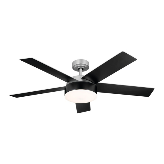
- Page 1 52" Compass LED Product images may vary slightly from actual product. INSTRUCTION MANUAL Model#: 300322...
-
Page 2: Table Of Contents
TABLE OF CONTENTS SAFETY RULES …………………………………………………………………………..3 ATTACHING THE FAN BLADES …………………………......11 TOOLS REQUIRED …………………………..………………………………..………...4 INSTALLING THE LIGHT PLATE ASSEMBLY……………....12 PACKAGE CONTENTS ……………….....……………………………...4 INSTALLING THE LIGHT KIT AND ACRYLIC SHADE…….....13 MOUNTING OPTIONS …………..............5 OPERATING INSTRUCTIONS …………………………...…………..14 HANGING THE MOTOR ASSEMBLY…………………………………………..6 TROUBLESHOOTING …………………………....………………...……16 ELECTRICAL CONNECTIONS…………..........9 FCC INFORMATION..………………………………………………………...17... -
Page 3: Safety Rules
SAFETY RULES READ AND SAVE THESE INSTRUCTIONS CAUTION CAUTION – RISK OF SHOCK – Make sure the installation site you choose allows a minimum clearance of 7 feet from the blades to the floor Disconnect Power at the main circuit breaker panel or and at least 30 inches from the ends of the blades to any main fuse box before starting and during the installation. -
Page 4: Tools Required
TOOLS REQUIRED Phillips screwdriver Blade screwdriver 11 mm wrench Step ladder Wire cutters PACKAGE CONTENTS Unpack your fan and check the contents . You should have the following items: A. Mounting bracket K .Remote Control Kit: B. Ball / downrod assembly Remote Control (1) C. -
Page 5: Mounting Options
MOUNTING OPTIONS If there is not an existing UL (cUL for Canadian Installation ) listed mounting box, then read the following instructions. Disconnect the power by removing fuses or turning off circuit breakers. Secure the outlet box directly to the building structure. Use Outlet box appropriate fasteners and building materials. -
Page 6: Hanging The Motor Assembly
HANGING THE MOTOR ASSEMBLY Outlet Box REMEMBER REMEMBER to turn off the power before you begin installation. This is Washer necessary for your safety and also the proper programming of the control system. To properly install your ceiling fan, follow the steps below. Screw Step 1. - Page 7 HANGING THE MOTOR ASSEMBLY Clevis Pin Step 3. Step 3. Remove the hairpin and clevis pin from the downrod assembly, retain for later use.(Fig.8) Hair pin Fig. 8 Set Screw Step 4. Step 4. Loosen the two set screws on the motor coupling.(Fig. 9) Fig.
- Page 8 HANGING THE MOTOR ASSEMBLY Step 6. Step 6. Insert the clevis pin through the downrod and coupling found on the Hairpin Clevis Pin motor assembly, and secure with the hair pin. Tighten set screws found on Set Screw the coupling. (Fig. 11 ) Coupling Fig.
-
Page 9: Electrical Connections
ELECTRICAL CONNECTIONS Mounting Bracket Receiver WARNING: WARNING: To avoid possible electrical shock, be sure you have turned off To avoid possible electrical shock, be sure you have turned off 6 to 9 in. the power at the main circuit panel before wiring. Follow the steps below the power at the main circuit panel before wiring. -
Page 10: Finishing The Motor Installation
ELECTRICAL CONNECTIONS Mounting Bracket Step 4. Step 4. If your outlet box has a ground wire ( green or bare copper ) connect If your outlet box has a ground wire ( green or bare copper ) connect it to the fan ground wires : otherwise connect the fan ground wire to the it to the fan ground wires : otherwise connect the fan ground wire to the mounting bracket. -
Page 11: Attaching The Fan Blades
FINISHING THE MOTOR INSTALLATION Step 3. Step 3. Securely attach and tighten the canopy hole cover over the shoulder Securely attach and tighten the canopy hole cover over the shoulder screws in the mounting bracket utilizing the keyslot twist-lock feature. (Fig.17) screws in the mounting bracket utilizing the keyslot twist-lock feature. -
Page 12: Installing The Light Plate Assembly
INSTALLING THE LIGHT PLATE ASSEMBLY Step 1. Step 1. Remove one of three screws which preinstalled on mounting plate and Remove one of three screws which preinstalled on mounting plate and keep for later use, loosen the other two (do not remove). (Fig. 19) keep for later use, loosen the other two (do not remove). -
Page 13: Installing The Light Kit And Acrylic Shade
INSTALLING THE LIGHT KIT AND ACRYLIC SHADE NOTE: NOTE: Before continuing installation, confirm that the power is still turned off Before continuing installation, confirm that the power is still turned off at the main circuit breaker or by removing the circuit fuse. Turning the power at the main circuit breaker or by removing the circuit fuse. -
Page 14: Operating Instructions
OPERATING INSTRUCTIONS Restore electrical power to the outlet box by turning the electricity on the Restore electrical power to the outlet box by turning the electricity on the main fuse box. main fuse box. Step 1. Step 1. Select a location to install your handset control holder, install the Select a location to install your handset control holder, install the holder as shown. - Page 15 OPERATING INSTRUCTIONS For DIMMER function: press and hold For DIMMER function: press and hold button to dim the light. The light will button to dim the light. The light will cycle from bright to dim to bright until button is released. Light will maintain cycle from bright to dim to bright until button is released.
-
Page 16: Troubleshooting
TROUBLESHOOTING Problem Problem Solution Solution Fan will not start. Fan will not start. 1. Check circuit fuses or breakers. 1. Check circuit fuses or breakers. 2. Check all electrical connections to ensure proper contact. CAUTION: Make sure the main power is OFF when checking 2. -
Page 17: Fcc Information
FCC Information This device complies with part 15 of the FCC Rules. Operation is subject to the following two conditions: 1.)This device may not cause harmful interference, and 2.)This device must accept any interference received, including interference that may cause undesired operation. Note: Note: This equipment has been tested and found to comply with the limits for a Class B digital device, pursuant to part 15 of the FCC Rules. - Page 18 KICHLER LIGHTING LLC 7711 EAST PLEASANT VALLEY ROAD CLEVELAND, OHIO 44131-8010 CUSTOMER SERVICE 866.558.5706 8:00 AM TO 5:00 PM EST, MONDAY - FRIDAY © Kichler Lighting LLC. All Rights Reserved.
- Page 19 52" Compass LED Les images des produits peuvent différer légèrement du produit réel. MANUEL D’INSTRUCTION Modèle #: 300322...
- Page 20 TABLE DES MATIÈRES RÈGLES DE SÉCURITÉ ................3 FIXATION DES PALES DU VENTILATEUR ........11 OUTILS NÉCESSAIRES ................4 INSTALLATION DE L’ASSEMBLAGE DE LA PLAQUE CONTENU DE L’EMBALLAGE ............4 D'ÉCLAIRAGE ..................12 OPTIONS DE MONTAGE ................ 5 INSTALLATION DU KIT D’ÉCLAIRAGE ET DE L’OMBRE SUSPENSION DE L’ASSEMBLAGE DU MOTEUR ......6 ACRYLIQUE ....................
-
Page 21: Règles De Sécurité
RÈGLES DE SÉCURITÉ VEUILLEZ LIRE ET CONSERVER LES PRÉSENTES INSTRUCTIONS MISE EN GARDE MISE EN GARDE – RISQUE D’ÉLECTROCUTION – – RISQUE D’ÉLECTROCUTION – Assurez-vous que l'endroit d'installation que vous choisissez permet un dégagement minimum de 7 pieds Débranchez l'alimentation électrique au niveau du Débranchez l'alimentation électrique au niveau du des pales au plancher et d'au moins 30 pouces des panneau de disjoncteurs principal ou de la boîte à... -
Page 22: Outils Nécessaires
OUTILS NÉCESSAIRES Lame de tournevis Phillips Clés de tournevis 11 mm Escabeau Coupe-fils CONTENU DE L’EMBALLAGE Déballez votre ventilateur et vérifiez son contenu. Les articles suivants doivent être disponibles: A. Support de montage K .Kit de télécommande: B. Assemblage de la boule Télécommande (1) et de la tige de descente Récepteur (1) -
Page 23: Options De Montage
OPTIONS DE MONTAGE S'il n'y a pas de boîtier de montage homologué UL (cUL pour installation au Canada), lisez les instructions suivantes. Coupez l'alimentation électrique en retirant les fusibles ou en coupant les disjoncteurs. Boîtier externe Fixer le boîtier externe directement sur la structure du bâtiment. Utiliser des attaches et des matériaux de construction appropriés. -
Page 24: Suspension De L'assemblage Du Moteur
SUSPENSION DE L’ASSEMBLAGE DU MOTEUR Boîtier externe TOUJOURS TOUJOURS mettre l'appareil hors tension avant de commencer l'installation. mettre l'appareil hors tension avant de commencer l'installation. Rondelle Ceci est nécessaire pour votre sécurité et aussi pour la programmation Ceci est nécessaire pour votre sécurité et aussi pour la programmation correcte du système de contrôle. - Page 25 SUSPENSION DE L’ASSEMBLAGE DU MOTEUR Goupille de blocage Étape 3. Étape 3. Retirez l'épingle à cheveux et la goupille de blocage de l'ensemble de Retirez l'épingle à cheveux et la goupille de blocage de l'ensemble de la tige descendante, conservez-les pour une utilisation ultérieure (Fig.8). la tige descendante, conservez-les pour une utilisation ultérieure (Fig.8).
- Page 26 SUSPENSION DE L’ASSEMBLAGE DU MOTEUR Étape 6. Étape 6. Faites passer l'axe de la chape à travers la tige descendante et Faites passer l'axe de la chape à travers la tige descendante et Épingle à cheveux Goupille de l'accouplement se trouvant sur l'ensemble du moteur, et fixez-le avec la l'accouplement se trouvant sur l'ensemble du moteur, et fixez-le avec la blocage Vis de réglage...
-
Page 27: Branchements Électriques
BRANCHEMENTS ÉLECTRIQUES Support de montage Récepteur AVERTISSEMENT : AVERTISSEMENT : Pour éviter tout risque de choc électrique, assurez-vous Pour éviter tout risque de choc électrique, assurez-vous 6 à 9 po. d'avoir coupé le courant au panneau de circuit principal avant de procéder d'avoir coupé... -
Page 28: Terminer De L'installation Du Moteur
BRANCHEMENTS ÉLECTRIQUES Support de montage Étape 4. Étape 4. Si votre boîtier de prise de courant est équipé d'un fil de terre (vert Si votre boîtier de prise de courant est équipé d'un fil de terre (vert ou cuivre nu), connectez le aux fils de terre du ventilateur. Sinon, connectez ou cuivre nu), connectez le aux fils de terre du ventilateur. -
Page 29: Fixation Des Pales Du Ventilateur
TERMINER DE L’INSTALLATION DU MOTEUR Étape 3. Étape 3. Fixez et serrez fermement le couvercle du trou de l'auvent sur les vis Fixez et serrez fermement le couvercle du trou de l'auvent sur les vis à épaulement du support de montage en utilisant le dispositif de verrouillage à... -
Page 30: Installation De L'assemblage De La Plaque
INSTALLATION DE L’ASSEMBLAGE DE LA PLAQUE D'ÉCLAIRAGE Étape 1. Étape 1. Retirez l’une des trois vis qui a été préinstallée sur la plaque de Retirez l’une des trois vis qui a été préinstallée sur la plaque de montage et conservez-la pour une utilisation ultérieure. Desserrez les deux montage et conservez-la pour une utilisation ultérieure. -
Page 31: Installation Du Kit D'éclairage Et De L'ombre
INSTALLATION DU KIT D'ÉCLAIRAGE ET DE L’OMBRE ACRYLIQUE REMARQUE : REMARQUE : Avant de poursuivre l'installation, vérifiez que l'alimentation est Avant de poursuivre l'installation, vérifiez que l'alimentation est toujours coupée au niveau du disjoncteur principal ou en retirant le fusible du toujours coupée au niveau du disjoncteur principal ou en retirant le fusible du Assemblage de la plaque d’éclairage... -
Page 32: Instructions De Fonctionnement
INSTRUCTIONS DE FONCTIONNEMENT Restaurer l’alimentation électrique au niveau de la boîte de sortie en Restaurer l’alimentation électrique au niveau de la boîte de sortie en rétablissant l’électricité au niveau de la boîte à fusible. rétablissant l’électricité au niveau de la boîte à fusible. Étape 1: Étape 1: Choisissez un emplacement pour installer votre support de la Choisissez un emplacement pour installer votre support de la... - Page 33 INSTRUCTIONS DE FONCTIONNEMENT Pour la fonction DIMMER : Appuyez sur le Pour la fonction DIMMER : Appuyez sur le bouton et maintenez-le enfoncé bouton et maintenez-le enfoncé pour diminuer la lumière. La lumière va passer de forte à faible jusqu’à ce que pour diminuer la lumière.
-
Page 34: Dépannage
DÉPANNAGE Problème Problème Solution Solution Le ventilateur ne Le ventilateur ne 1- Vérifiez les fusibles ou les disjoncteurs. 1- Vérifiez les fusibles ou les disjoncteurs. démarre pas démarre pas 2- Vérifiez toutes les connexions électriques pour assurer un contact correct. ATTENTION : Assurez-vous que l'alimentation 2- Vérifiez toutes les connexions électriques pour assurer un contact correct. -
Page 35: Information Fcc
Information FCC Cet appareil est conforme à la section 15 des règlements FCC. Le fonctionnement est soumis aux deux conditions suivantes: 1.)cet appareil ne doit pas causer d’interférences nuisibles, et 2.)cet appareil doit accepter toute interférence reçue, y compris les interférences qui peuvent causer un fonctionnement indésirable. - Page 36 KICHLER LIGHTING LLC 7711 EAST PLEASANT VALLEY ROAD CLEVELAND, OHIO 44131-8010 SERVICE À LA CLIENTÈLE 866.558.5706 08:00 à 17:00 PM EST, LUNDI- VENDREDI © Kichler Lighting LLC. Tous droits réservés.
- Page 37 52" Compass LED Las imágenes pueden presentar diferencias con respecto al producto recibido. MANUAL DE INSTRUCCIONES Modelo No.: 300322...
- Page 38 ÍNDICE NORMAS DE SEGURIDAD ..............3 COLOCACIÓN DE LAS ASPAS DEL VENTILADOR ....11 HERRAMIENTAS NECESARIAS ............4 INSTALACIÓN DEL CONJUNTO DE LA PLACA DE CONTENIDO DEL EMBALAJE ............4 ILUMINACIÓN....................12 OPCIONES DE MONTAJE ..............5 INSTALANDO EL KIT DE ILUMINACIÓN Y EL DOSEL COLGANDO EL CONJUNTO DEL MOTOR ........
-
Page 39: Normas De Seguridad
NORMAS DE SEGURIDAD LEA Y GUARDE ESTAS INSTRUCCIONES PRECAUCIONES PRECAUCIONES - RIESGO DE DESCARGA ELÉCTRICA - RIESGO DE DESCARGA ELÉCTRICA Asegúrese de que el lugar de instalación que elija permita - Desconecte la alimentación en el panel del disyuntor - Desconecte la alimentación en el panel del disyuntor un espacio mínimo de 7 pies (2 metros) entre las aspas y el principal o en la caja de fusibles principal antes de principal o en la caja de fusibles principal antes de... -
Page 40: Herramientas Necesarias
HERRAMIENTAS NECESARIAS Destornillador Phillips Destornillador plano Llave de 11 mm.. Escaleras de tijera (de mano). Alicates/tenazas cortacables CONTENIDO DEL EMBALAJE Desembale su ventilador y compruebe el contenido. Debe tener los siguientes elementos: A. Soporte del montaje K. Kit de control remoto: B. -
Page 41: Opciones De Montaje
OPCIONES DE MONTAJE Si no hay una caja de montaje listada por UL (CUL para la instalación canadiense), lea las siguientes instrucciones. Desconecte la corriente quitando los fusibles o apagando el cortacircuitos. Asegure la caja de distribución directamente a la estructura del Caja de distribución edificio. -
Page 42: Colgando El Conjunto Del Motor
COLGANDO EL CONJUNTO DEL MOTOR Caja de distribución RECUERDE RECUERDE desconectar/apagar la corriente antes de empezar con la desconectar/apagar la corriente antes de empezar con la Arandela instalación y el cableado. Esto es necesario para su seguridad y también para instalación y el cableado. - Page 43 COLGANDO EL CONJUNTO DEL MOTOR Perno de la horquilla Paso 3. Paso 3. Quite el pasador y el perno de la horquilla del montaje de la tija, y Quite el pasador y el perno de la horquilla del montaje de la tija, y consérvelos para su uso posterior.
- Page 44 COLGANDO EL CONJUNTO DEL MOTOR Paso 6. Paso 6. Inserte el perno de horquilla a través de la tija y en el tubo de Inserte el perno de horquilla a través de la tija y en el tubo de Pasador de horquilla Perno de la acoplamiento que se encuentra en el montaje del motor, y asegúrelo con acoplamiento que se encuentra en el montaje del motor, y asegúrelo con...
-
Page 45: Conexiones Eléctricas
CONEXIONES ELÉCTRICAS Soporte del montaje Receptor ADVERTENCIA: ADVERTENCIA: Para evitar posibles descargas eléctricas, asegúrese de Para evitar posibles descargas eléctricas, asegúrese de 6 a 9 haber cortado la corriente en el panel del circuito principal antes de realizar haber cortado la corriente en el panel del circuito principal antes de realizar pulgadas el cableado. -
Page 46: Acabando La Instalación Del Motor
CONEXIONES ELÉCTRICAS Soporte del montaje Paso 4. Paso 4. Si su caja de distribución tiene un cable de tierra (verde o cobre Si su caja de distribución tiene un cable de tierra (verde o cobre desnudo) conéctelo a los cables de tierra del ventilador; de lo contrario, desnudo) conéctelo a los cables de tierra del ventilador;... -
Page 47: Colocación De Las Aspas Del Ventilador
ACABANDO LA INSTALACIÓN DEL MOTOR Paso 3. Paso 3. Fije y apriete firmemente la tapa del agujero de la cubierta sobre los Fije y apriete firmemente la tapa del agujero de la cubierta sobre los tornillos de los hombros en el soporte de montaje utilizando la característica tornillos de los hombros en el soporte de montaje utilizando la característica de giro de la ranura de la llave. -
Page 48: Instalación Del Conjunto De La Placa De
INSTALACIÓN DEL CONJUNTO DE LA PLACA DE ILUMINACIÓN Paso 1. Paso 1. Retire uno de los tres tornillos preinstalados en la placa de montaje y Retire uno de los tres tornillos preinstalados en la placa de montaje y guárdelo para su uso posterior, afloje los otros dos (no los retire). (Img. 19) guárdelo para su uso posterior, afloje los otros dos (no los retire). -
Page 49: Instalando El Kit De Iluminación Y El Dosel
INSTALANDO EL KIT DE ILUMINACIÓN Y EL DOSEL ACRÍLICO NOTA: NOTA: Antes de continuar con la instalación, confirme que la energía sigue Antes de continuar con la instalación, confirme que la energía sigue apagada en el interruptor principal o quitando el fusible del circuito. apagada en el interruptor principal o quitando el fusible del circuito. -
Page 50: Instrucciones De Uso
INSTRUCCIONES DE USO Restablezca la energía eléctrica en la caja de salida encendiendo la Restablezca la energía eléctrica en la caja de salida encendiendo la electricidad en la caja de fusibles principal. electricidad en la caja de fusibles principal. Paso 1. Paso 1. - Page 51 INSTRUCCIONES DE USO Para la función de atenuación: pulse y mantenga pulsado el botón Para la función de atenuación: pulse y mantenga pulsado el botón para para atenuar la luz. La luz pasará de brillante a tenue y otra vez a brillante hasta atenuar la luz.
-
Page 52: Solución De Problemas
SOLUCIÓN DE PROBLEMAS Problema Problema Solución Solución El ventilador no se El ventilador no se 1. Revise los fusibles o los disyuntores del circuito. 1. Revise los fusibles o los disyuntores del circuito. enciende. enciende. 2. Revise todas las conexiones eléctricas para asegurar un contacto adecuado. PRECAUCIÓN: Asegúrese de que la 2. -
Page 53: Información De La Fcc
INFORMACIÓN DE LA FCC Este dispositivo cumple con la parte 15 de las normas de la FCC. Su funcionamiento está sujeto a las dos condiciones siguientes: 1.)Este dispositivo no puede causar interferencias perjudiciales, y 2.)Este dispositivo debe aceptar cualquier interferencia recibida, incluyendo las interferencias que puedan causar un funcionamiento no deseado. - Page 54 KICHLER LIGHTING LLC 7711 EAST PLEASANT VALLEY ROAD CLEVELAND, OHIO 44131 - 8010 SERVICIO DE ATENCIÓN AL CLIENTE 866 558 5706 DE LUNES A VIERNES, 8:00 MAÑANA A 5:00 TARDE (EST.) © Kichler Lighting LLC. Todos los derechos reservados.
Need help?
Do you have a question about the Compass 300322 and is the answer not in the manual?
Questions and answers