
Related Manuals for H3C S6520XE-HI Series


Summary of Contents for H3C S6520XE-HI Series
- Page 1 H3C S6520XE-HI Switch Series Installation Guide New H3C Technologies Co., Ltd. http://www.h3c.com Document version: 6W103-20200220...
- Page 2 No part of this manual may be reproduced or transmitted in any form or by any means without prior written consent of New H3C Technologies Co., Ltd. Trademarks Except for the trademarks of New H3C Technologies Co., Ltd., any trademarks that may be mentioned in this document are the property of their respective owners. Notice The information in this document is subject to change without notice.
- Page 3 Preface H3C S6520XE-HI Switch Series Installation Guide describes the appearance, installation, power-on, maintenance, and troubleshooting of the H3C S6520XE-HI Switch Series. This preface includes the following topics about the documentation: • Audience. • Conventions • Documentation feedback Audience This documentation is intended for: •...
- Page 4 Symbols Convention Description An alert that calls attention to important information that if not understood or followed WARNING! can result in personal injury. An alert that calls attention to important information that if not understood or followed CAUTION: can result in data loss, data corruption, or damage to hardware or software. An alert that calls attention to essential information.
- Page 5 Documentation feedback You can e-mail your comments about product documentation to info@h3c.com. We appreciate your comments.
-
Page 6: Table Of Contents
Contents Preparing for installation ···································································· 1 Safety recommendations ············································································································· 1 Examining the installation site ······································································································· 1 Temperature/humidity ·········································································································· 1 Cleanliness ························································································································ 2 EMI ·································································································································· 2 Laser safety ······················································································································· 3 Installation tools ························································································································· 3 ... - Page 7 Appendix A Chassis views and technical specifications ·························· 32 Chassis views ························································································································· 32 S6520XE-54QC-HI ············································································································ 32 Technical specifications ············································································································· 33 Appendix B FRUs and compatibility matrixes ······································· 34 Power modules ······················································································································· 34 Fan trays ································································································································ 34 ...
-
Page 8: Preparing For Installation
Preparing for installation The H3C S6520XE-HI Switch Series includes only the S6520XE-54QC-HI switch model. Safety recommendations To avoid any equipment damage or bodily injury caused by improper use, read the following safety recommendations before installation. Note that the recommendations do not cover every possible hazardous condition. -
Page 9: Cleanliness
• Lasting low relative humidity can cause washer contraction and ESD and cause problems including loose mounting screws and circuit failure. • High temperature can accelerate the aging of insulation materials and significantly lower the reliability and lifespan of the switch. For the temperature and humidity requirements, see "Technical specifications."... -
Page 10: Laser Safety
Laser safety WARNING! Do not stare into any fiber port when the switch has power. The laser light emitted from the optical fiber might hurt your eyes. The S6520XE-HI switch is a Class 1 laser device. Installation tools No installation tools are provided with the switch. Prepare the following tools yourself: •... -
Page 11: Installing The Switch
CAUTION: Keep the tamper-proof seal on a mounting screw on the chassis cover intact, and if you want to open the chassis, contact H3C for permission. Otherwise, H3C shall not be liable for any consequence. Figure 1 Hardware installation flow... -
Page 12: Installing The Switch In A 19-Inch Rack
Installing the switch in a 19-inch rack Installation requirements Table 3 Installation requirements for the S6520XE-HI switches Installation Installation Installation requirements method procedure • Install the front mounting brackets at the power module side or port side. • Install the rear mounting brackets as required by the rack depth: Using the front "Rack-mounting by... -
Page 13: Rack-Mounting By Using The Front And Rear Mounting Brackets
Figure 4 Rear mounting bracket and shoulder screw (1) Hole for attaching the bracket to a rack post (2) Shoulder screw Rack-mounting by using the front and rear mounting brackets You can install the front mounting brackets at the port-side or power-side mounting position as needed. - Page 14 Attach the rear mounting brackets to the rack: Orient the brackets with the wide flange inside or outside the rack as required. a. Install cage nuts (user-supplied) in the mounting holes in the rear rack posts. Make sure the corresponding cage nuts on the left and right rear rack posts are at the same height.
- Page 15 Mount the switch chassis in the rack: a. Install cage nuts (user-supplied) on the front rack posts. Make sure the corresponding cage nuts on the left and right front rack posts are at the same height. b. One person supports the chassis bottom with one hand, holds the front part of the chassis with the other hand, and pushes the chassis into the rack gently.
-
Page 16: Mounting The Switch On A Workbench
Figure 9 Mounting the switch in the rack (with the wide flange of the rear mounting brackets outside the rack) Mounting the switch on a workbench IMPORTANT: • Ensure good ventilation and 10 cm (3.9 in) of clearance around the chassis for heat dissipation. •... -
Page 17: Grounding The Switch With A Grounding Strip
NOTE: • The power and grounding terminals in this section are for illustration only. • To guarantee the grounding effect, use the grounding cable provided with the switch to connect to the grounding strip in the equipment room. Grounding the switch with a grounding strip WARNING! Connect the grounding cable to the grounding system in the equipment room. -
Page 18: Grounding The Switch With A Grounding Conductor Buried In The Earth Ground
Figure 11 Attaching a ring terminal to the grounding cable Connect the ring terminal to the grounding post of the grounding strip, and fasten it with the removed hex nut. Figure 12 Connecting the grounding cable to a grounding strip (1) Grounding post (2) Grounding strip (3) Grounding cable... -
Page 19: Installing/Removing A Fan Tray
Figure 13 Grounding the switch by burying the grounding conductor into the earth ground (1) Grounding screw (2) Chassis rear panel (3) Grounding cable (4) Earth (5) Joint (6) Grounding conductor Installing/removing a fan tray CAUTION: • Install two fan trays of the same model on the switch. Do not power on the switch when it does not have fan trays or has only one fan tray installed. -
Page 20: Removing A Fan Tray
Figure 14 Installing a fan tray IMPORTANT: • At the first login to the switch, use the fan prefer-direction command to set the airflow direction of the switch to be the same as the airflow direction of the fan tray. If the fan tray has a different airflow direction than the switch, the system outputs traps and logs to notify you to replace the fan tray. -
Page 21: Installing/Removing A Power Module
Installing/removing a power module WARNING! In power redundancy mode, you can replace a power module without powering off the switch but you must strictly follow the installation and procedures in Figure 16 Figure 17 to avoid any bodily injury or damage to the switch. CAUTION: •... -
Page 22: Removing A Power Module
Correctly orient the power module. Grasp the handle of the power module with one hand and support its bottom with the other, and slide the power module slowly along the guide rails into the slot until it clicks into place. To prevent damage to the power module or the connectors on the backplane, insert the power module gently. -
Page 23: Installing/Removing An Expansion Card
Figure 20 Connecting the power cord to the power module Use a cable tie to secure the power cord to the handle of the power module. Figure 21 Securing the power cord with a cable tie (1) Figure 22 Securing the power cord with a cable tie (2) Connect the other end of the power cord to the power outlet. -
Page 24: Installing An Expansion Card
Installing an expansion card Wear an ESD wrist strap and make sure it makes good skin contact and is reliably grounded. Use a Phillips screwdriver to remove the mounting screw on the filler panel over the expansion slot. Use a flat-head screwdriver to prize outwards the filler panel. Then, remove the filler panel. Keep the filler panel for future use. -
Page 25: Removing An Expansion Card
NOTE: The LSPM6FWD firewall card adds 75 mm (2.95 in) to the chassis depth, which includes the handle of the firewall card. Removing an expansion card Wear an ESD wrist strap and make sure it makes good skin contact and is correctly grounded. Use a Phillips screwdriver to completely loosen the captive screw on the expansion card. -
Page 26: Accessing The Switch For The First Time
USB console port. No serial console cable or micro USB console cable is provided with the switch. You can prepare the cable yourself or purchase one from H3C. Figure 25 Connecting the serial console port to a terminal... -
Page 27: Connecting The Micro Usb Console Cable
Click the following link, or copy it to the address bar on a browser to log in to the download page of the USB console driver, and download the driver. http://www.h3c.com/en/support/resource_center/hk/other_product/usb_console/usb_console/ ?tbox=Software Select a driver program according to the operating system you use: XR21V1410_XR21B1411_Windows_Ver1840_x86_Installer.EXE—32-bit operating... - Page 28 Figure 27 Device Driver Installation Wizard Click Continue Anyway if the following dialog box appears. Figure 28 Software Installation Click Finish.
-
Page 29: Setting Terminal Parameters
Figure 29 Completing the device driver installation wizard Setting terminal parameters To configure and manage the switch through the console port, you must run a terminal emulator program, HyperTerminal or PuTTY, on your configuration terminal. You can use the emulator program to connect a network device, a Telnet site, or an SSH site. - Page 30 After the startup completes, you can access the CLI to configure the switch. For more information about the configuration commands and CLI, see H3C S6520XE-HI Switch Series Configuration Guides and H3C S6520XE-HI Switch Series Command References.
-
Page 31: Setting Up An Irf Fabric
Setting up an IRF fabric You can use H3C IRF technology to connect and virtualize S6520XE-HI switches into a large virtual switch called an "IRF fabric" for flattened network topology, and high availability, scalability, and manageability. IRF fabric setup flowchart... -
Page 32: Planning Irf Fabric Setup
CLI of the master switch. IRF member switches automatically elect a master. You can affect the election result by assigning a high member priority to the intended master switch. For more information about master election, see H3C S6520XE-HI Switch Series Virtual Technologies Configuration Guide. -
Page 33: Planning Irf Topology And Connections
Planning IRF topology and connections You can create an IRF fabric in daisy chain topology or more reliable ring topology. In ring topology, the failure of one IRF link does not cause the IRF fabric to split as in daisy chain topology. Instead, the IRF fabric changes to a daisy chain topology without interrupting network services. -
Page 34: Identifying Physical Irf Ports On The Member Switches
"Appendix C Ports and LEDs." The following subsections describe several H3C recommended IRF connection schemes, and all these schemes use a ring topology. IMPORTANT: In these schemes, all physical IRF ports are located on the same side. If physical IRF ports are on different sides, you must measure the distance between them to select an appropriate cable. - Page 35 Figure 33 Connecting the switches in one rack Figure 34 IRF fabric topology Connecting the IRF member switches in a ToR solution You can install IRF member switches in different racks side by side to deploy a top of rack (ToR) solution.
-
Page 36: Configuring Basic Irf Settings
To bind the ports on an interface card to an IRF port, you must install the interface card first. • Execute the display irf configuration command to verify the basic IRF settings. For more information about configuring basic IRF settings, see H3C S6520XE-HI Switch Series Virtual Technologies Configuration Guide. Connecting the physical IRF ports Use twisted pair/SFP+/QSFP+/QSFP+ to SFP+ cables or SFP+/QSFP+ transceiver modules and fibers to connect the IRF member switches as planned. -
Page 37: Maintenance And Troubleshooting
For more information about the PWR1 and PWR2 LEDs on the front panel of the switch, Table • For more information about the LEDs on a power module, see H3C PSR250-12A & PSR250-12A1 Power Modules User Manual. Symptom The power module status LEDs are not steady green. -
Page 38: Garbled Terminal Display
Verify that the power module is supplying power to the switch. Verify that the console cable is correctly connected. Verify that the console cable does not have any problems and the terminal settings are correct. If the issue persists, contact H3C Support. Garbled terminal display Symptom Terminal display is garbled. -
Page 39: Appendix A Chassis Views And Technical Specifications
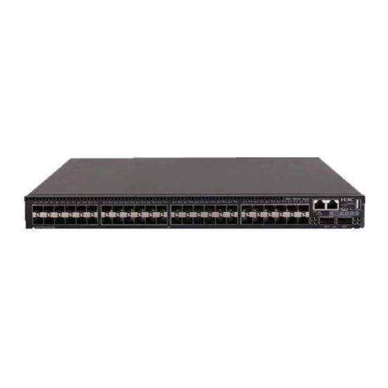
Appendix A Chassis views and technical specifications Chassis views S6520XE-54QC-HI Figure 36 S6520XE-54QC-HI front panel (1) SFP+ port (2) SFP+ port LED (3) Management Ethernet port (4) Management Ethernet port LED (5) Serial console port (6) Micro USB console port (7) LED for the port LED mode (MODE) (8) USB port (9) Port LED mode switching button... -
Page 40: Technical Specifications
The S6520XE-54QC-HI switch comes with the two fan tray slots empty. You must install two fan trays of the same model for the switch. In Figure 37, two LSWM1FANSCE fan trays are installed in the fan tray slots. For more information about installing and removing a fan tray, see "Installing/removing a tray."... -
Page 41: Appendix B Frus And Compatibility Matrixes
LSWM1FANSCBE: From the port side to the power module side Input voltage 12 V Maximum power consumption 27.72 W Reference H3C LSWM1FANSCE & LSWM1FANSCBE Fan Trays User Guide Expansion cards Table 10 Expansion cards available for the switch Item Specifications LSWM2QP2P... - Page 42 8 × 1/10 Gbps SFP+ fiber ports Available transceiver modules Table Table 15, and Table and cables H3C LSWM2SP8PM & LSWM2SP8P Interface Cards User Manual Reference H3C LSWM4SP8PM Interface Card User Manual LSWM2SP2PM Description 2-port 10GE SFP+ interface card Port type and quantity 2 ×...
- Page 43 When you connect cables to the ports on the interface cards, follow these restrictions and guidelines: • Use category-6A or above cables and connectors. • Do not bundle cables in their first 20 m (65.62 ft). • Separate power cords and twisted pair cables at and around the distribution frame. •...
-
Page 44: Appendix C Ports And Leds
NOTE: USB devices from different vendors vary in compatibilities and drivers. H3C does not guarantee the correct operation of USB devices from all vendors on the switch. If a USB device fails to operate on... -
Page 45: 1/10Gbase-T Autosensing Ethernet Port
1/10GBase-T autosensing Ethernet port The LSWM2XGT2PM interface card provides 1/10GBase-T autosensing Ethernet ports. Table 13 1/10GBase-T autosensing Ethernet port specifications Item Specification Connector type RJ-45 Interface attributes 1/10 Gbps, full duplex, MDI/MDI-X auto-sensing • Category-6 UTP—55 m (180.45 ft) • Category-6 STP—100 m (328.09 ft) Transmission medium and max transmission distance... - Page 46 GE SFP Multimode Central Cable/fiber transceiver fiber modal Max transmission wavelength Connector diameter module and bandwidth distance (nm) (µm) cable (MHz × km) Single-mode, 10 km (6.21 miles) 9/125 SFP-GE-LX-SM Multi-mode, 1310 500 or 400 550 m (1804.46 ft) 1310-A 50/125 Multi-mode, 550 m (1804.46 ft)
- Page 47 Multimode Central Fiber Module fiber modal Max transmission wavelength Connector diameter description bandwidth distance (nm) (µm) (MHz × km) 2000 300 m (984.25 ft) Multi-mode, 82 m (269.03 ft) 50/125 SFP-XG-SX-MM 66 m (216.54 ft) 850-D 33 m (108.27 ft) Multi-mode, 62.5/125 26 m (85.30 ft)
-
Page 48: Qsfp+ Port
NOTE: • As a best practice, use only H3C SFP/SFP+ transceiver modules and SFP+ cables for the SFP+ ports. • The H3C SFP/SFP+ transceiver modules and SFP+ cables available for the SFP+ ports are subject to change over time. For the most recent list of SFP/SFP+ transceiver modules and SFP+ cables, contact your H3C Support or marketing staff. -
Page 49: Leds
(4) SFP+ module NOTE: • As a best practice, use H3C QSFP+ transceiver modules, QSFP+ cables, or QSFP+ to SFP+ cables for the QSFP+ ports on the switch. The H3C QSFP+ transceiver modules, QSFP+ cables, and QSFP+ to SFP+ cables available for the QSFP+ ports are subject to change over time. For the most recent list of QSFP+ transceiver modules, QSFP+ cables, and QSFP+ to SFP+ cables available for the QSFP+ ports, contact H3C Support or marketing staff. -
Page 50: Power Module Status Led
Table 20 System status LED description LED mark Status Description Steady green The switch is operating correctly. Flashing green The switch is performing power-on self test (POST). Steady red The switch has failed POST or is faulty. Flashing red Some ports on the switch have failed POST or are faulty. The switch is powered off or the system fails to start up. -
Page 51: Qsfp+ Port Led
QSFP+ port LED Table 23 QSFP+ port LED description MODE LED QSFP+ port Description status LED status A transceiver module is installed and a link is present on the port. Steady green The port is operating at 40 Gbps. Flashing green The port is sending or receiving data at 40 Gbps. -
Page 52: Expansion Card Status Led
Table 25 Management Ethernet port LED description ACT/LINK Description Steady green A link is present on the port. Flashing yellow The port is sending or receiving data. No link is present on the port. Expansion card status LED The expansion card status LED on the front panel indicates the operating state of the expansion card. -
Page 53: Appendix D Cooling System
Appendix D Cooling system CAUTION: To guarantee heat dissipation, you must install two fan trays of the same model for the switch. To dissipate heat timely and ensure system stability, the switch uses high-performance cooling system. Consider the site ventilation design when you plan the installation site for the switch. The switch uses hot-swappable fan trays.
Need help?
Do you have a question about the S6520XE-HI Series and is the answer not in the manual?
Questions and answers