H3C S6520X-EI Series Manual
Hide thumbs
Also See for S6520X-EI Series:
- Installation manual (77 pages) ,
- Hardware information (52 pages) ,
- Troubleshooting manual (50 pages)
Table of Contents
Advertisement
Quick Links
1
Product models and technical
specifications
Product models
H3C S6520X-EI switch series includes the following models:
•
S6520X-30QC-EI
•
S6520X-54QC-EI
•
S6520X-30HC-EI
•
S6520X-54HC-EI
•
S6520X-30HF-EI
•
S6520X-54HF-EI
H3C S6520X-HI switch series includes the following models:
•
S6520X-30QC-HI
•
S6520X-54QC-HI
•
S6520X-30HC-HI
•
S6520X-54HC-HI
•
S6520X-30HF-HI
•
S6520X-54HF-HI
Technical specifications
Table1-1 Technical specifications (1)
Item
Dimensions
(H × W × D)
Weight
Console port
USB port
Management
Ethernet port
QSFP+ port
SFP+ port
QSFP28 port
Expansion
S6520X-30QC-EI
S6520X-30QC-HI
43.6 × 440 × 360 mm
(1.72 × 17.32 × 14.17
in)
≤ 7.0 kg (15.43 lb)
•
1 × micro USB console port
•
1 × serial console port
Only the micro USB console port is available when you connect both ports.
1
1
2
24
N/A
2, on the rear panel
S6520X-54QC-EI
S6520X-30HC-EI
S6520X-54QC-HI
S6520X-30HC-HI
43.6 × 440 × 360
43.6 × 440 × 360 mm
mm (1.72 × 17.32 ×
(1.72 × 17.32 × 14.17
14.17 in)
in)
≤ 7.2 kg (15.87 lb)
≤ 7.4 kg (16.31 lb)
1
1
1
1
2
N/A
48
24
N/A
2
2, on the rear panel
2, on the rear panel
S6520X-54HC-EI
S6520X-54HC-HI
43.6 × 440 × 360
mm (1.72 × 17.32 ×
14.17 in)
≤ 7.6 kg (16.75 lb)
1
1
N/A
48
2
2, on the rear panel
Advertisement
Table of Contents

Related Manuals for H3C S6520X-EI Series


Summary of Contents for H3C S6520X-EI Series
- Page 1 Product models and technical specifications Product models H3C S6520X-EI switch series includes the following models: • S6520X-30QC-EI • S6520X-54QC-EI • S6520X-30HC-EI • S6520X-54HC-EI • S6520X-30HF-EI • S6520X-54HF-EI H3C S6520X-HI switch series includes the following models: • S6520X-30QC-HI • S6520X-54QC-HI •...
- Page 2 S6520X-30QC-EI S6520X-54QC-EI S6520X-30HC-EI S6520X-54HC-EI Item S6520X-30QC-HI S6520X-54QC-HI S6520X-30HC-HI S6520X-54HC-HI slot Power supply 2, on the rear panel 2, on the rear panel 2, on the rear panel 2, on the rear panel slot Fan tray slot 2, on the rear panel 2, on the rear panel 2, on the rear panel 2, on the rear panel...
- Page 3 Table1-2 Technical specifications (2) Item S6520X-30HF-EI S6520X-54HF-EI S6520X-30HF-HI S6520X-54HF-HI 44 × 440 × 360 mm 44 × 440 × 360 mm 44 × 440 × 360 mm 44 × 440 × 360 mm Dimensions (1.73 × 17.32 × (1.73 × 17.32 × (1.73 ×...
-
Page 4: Chassis Views
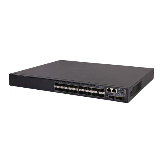
Chassis views S6520X-30QC-EI & S6520X-30QC-HI Figure2-1 Front panel 4 5 6 (1) SFP+ port (2) SFP+ port LED (3) Management Ethernet port (4) Console port (CONSOLE) (5) Micro USB console port (6) Mode LED (MODE) (7) USB port (8) Mode button (9) System status LED (SYS) (10) Expansion card 2 status LED (SLOT2) (11) Expansion card 1 status LED (SLOT1) - Page 5 S6520X-54QC-EI & S6520X-54QC-HI Figure2-3 Front panel (1) SFP+ port (2) SFP+ port LED (3) Management Ethernet port (4) Console port (CONSOLE) (5) Micro USB console port (6) Mode LED (MODE) (7) USB port (8) Mode button (9) System status LED (SYS) (10) Expansion card 2 status LED (SLOT2) (11) Expansion card 1 status LED (SLOT1) (12) Power supply 2 status LED (PWR2)
- Page 6 S6520X-30HC-EI & S6520X-30HC-HI Figure2-5 Front panel 4 5 6 (1) SFP+ port (2) SFP+ port LED (3) Management Ethernet port (4) Console port (CONSOLE) (5) Micro USB console port (6) Mode LED (MODE) (7) USB port (8) Mode button (9) System status LED (SYS) (10) Expansion card 2 status LED (SLOT2) (11) Expansion card 1 status LED (SLOT1) (12) Power supply 2 status LED (PWR2)
- Page 7 S6520X-54HC-EI & S6520X-54HC-HI Figure2-7 Front panel (1) SFP+ port (2) SFP+ port LED (3) Management Ethernet port (4) Console port (CONSOLE) (5) Micro USB console port (6) Mode LED (MODE) (7) USB port (8) Mode button (9) System status LED (SYS) (10) Expansion card 2 status LED (SLOT2) (11) Expansion card 1 status LED (SLOT1) (12) Power supply 2 status LED (PWR2)
- Page 8 S6520X-30HF-EI & S6520X-30HF-HI Figure2-9 Front panel (1) SFP+ port (2) SFP+ port LED (3) QSFP28 port (4) QSFP28 port LED (5) System status LED (SYS) Figure2-10 Rear panel (1) Management Ethernet port (2) Console port (CONSOLE) (3) USB port (4) Fan tray 1 (FAN1) (5) Fan tray 2 (FAN2) (6) Fan tray 3 (FAN3) (7) Power supply 1 (PWR1)
- Page 9 S6520X-54HF-EI & S6520X-54HF-HI Figure2-11 Front panel (1) SFP+ port (2) SFP+ port LED (3) QSFP28 port (4) QSFP28 port LED (5) System status LED (SYS) Figure2-12 Rear panel (1) Management Ethernet port (2) Console port (CONSOLE) (3) USB port (4) Fan tray 1 (FAN1) (5) Fan tray 2 (FAN2) (6) Fan tray 3 (FAN3) (7) Power supply 1 (PWR1)
- Page 10 Removable components and compatibility matrixes Table3-1 Compatibility matrix between switches and removable components S6520X-30QC-EI S6520X-30HC-EI S6520X-30HF-EI S6520X-30QC-HI S6520X-30HC-HI S6520X-54HF-EI model S6520X-54QC-EI S6520X-54HC-EI S6520X-30HF-HI S6520X-54QC-HI S6520X-54HC-HI S6520X-54HF-HI Removable power supplies PSR250-12 Supported Supported Not supported PSR250-12 Supported Supported Not supported PSR450-12 Supported Supported Not supported...
-
Page 11: Removable Power Supplies
DC input 320 VDC • Max output power: 250 W • Rated input voltage range: –48 to – 60 VDC H3C PSR450 Power Supply • Max input voltage range: –36 to – PSR450-12D DC input Series User Guide 72 VDC •... - Page 12 LSWM1FANSCE—From the power supply side to the port side Airflow direction • LSWM1FANSCBE—From the port side to the power supply side Reference H3C LSWM1FANSCE & LSWM1FANSCBE Fan Trays User Guide Table3-4 LSPM1FANSA-SN and LSPM1FANSB-SN fan tray specifications Item Specifications Dimensions (H × W × D) 40 ×...
-
Page 13: Expansion Cards
Available transceiver modules 10-GE SFP+ transceiver modules and cables described in Table4-4 and cables Table4-5. Reference H3C LSWM2SP8PM & LSWM2SP8P Interface Cards User Manual LSWM4SP8PM Description 8-port 10GE SFP+ interface module Port type and quantity Eight 1/10 Gbps SFP+ fiber ports... - Page 14 Port type and quantity Eight 10G/5G/2.5G/1000BASE-T autosensing Ethernet ports Port specifications Table4-16 for the port specifications. Reference H3C LSWM2MGT8P & LSWM2XMGT8P Interface Cards User Manual LSWM2MGT8P Description 8-port 1/2.5/5GBASE-T interface module Port type and quantity Eight 5G/2.5G/1000BASE-T autosensing Ethernet ports...
- Page 15 Item Specifications described in Table4-4, Table4-5, and Table4-6. H3C LSWM2SP2PB & LSWM2SP4PB Interface Cards User Manual Reference Connecting cables to the ports on interface modules To connect cables to the ports on interface modules, follow these guidelines: • Do not bundle cables in their first 20 m (65.62 ft).
-
Page 16: Console Port
Ports and LEDs Ports Console port Table4-1 Console port specifications Item Serial console port Micro USB console port Connector type RJ-45 Micro USB Type B Compliant standard EIA/TIA-232 USB 2.0 Transmission baud rate 9600 bps (default) to 115200 bps • Provides connection to an ASCII terminal. - Page 17 NOTE: USB devices from different vendors vary in compatibilities and drivers. H3C does not guarantee the correct operation of USB devices from all vendors on the switch. If a USB device fails to operate on the switch, replace it with one from another vendor.
- Page 18 GE SFP Central Cable/Fiber Modal transceiver wavelength Connector type and bandwidth transmission module and (nm) diameter (µm) (MHz × km) distance cable 50/125 Multi-mode, 550 m (1804.46 ft) 62.5/125 SFP-GE-LX-SM Single-mode, 1310 10 km (6.21 miles) 1310-D 9/125 SFP-GE-LX-SM Single-mode, 1310 10 km (6.21 miles) 1310-S...
- Page 19 IMPORTANT: The SFP-GE-LX-SM1310-BIDI and SFP-GE-LX-SM1490-BIDI transceiver modules, the SFP-GE-LH40-SM1310-BIDI and SFP-GE-LH40-SM1550-BIDI transceiver modules, and the SFP-GE-LH70-SM1490-BIDI and SFP-GE-LH70-SM1550-BIDI transceiver modules must be used in pairs. For example, if one end uses the SFP-GE-LX-SM1310-BIDI transceiver module, the other end must use the SFP-GE-LX-SM1490-BIDI transceiver module. Table4-4 10-GE SFP+ transceiver modules available for the SFP+ ports Central Fiber...
- Page 20 Central Fiber Modal 10-GE SFP+ wavelength Connector diameter bandwidth transmission module (nm) (µm) (MHz × km) distance -SM1550 9/125 SFP-XG-LH80 Single-mode, 1550 80 km (49.71 miles) -SM1550-D 9/125 TX: 1270 SFP-XG-LX-S Single-mode, 10 m (32.81 ft) M1270-BIDI 9/125 RX: 1330 TX: 1330 SFP-XG-LX-S Single-mode,...
-
Page 21: Sfp28 Port
• As a best practice, use H3C transceiver modules and network cables for the switch. • The H3C transceiver modules and network cables are subject to change over time. For the most recent list of H3C transceiver modules and cables, contact H3C Support or marketing staff. - Page 22 • As a best practice, use H3C transceiver modules and network cables for the switch. • The H3C transceiver modules and network cables are subject to change over time. For the most recent list of H3C transceiver modules and cables, contact H3C Support or marketing staff.
- Page 23 Table4-9 QSFP+ transceiver modules available for the QSFP+ ports QSFP+ Central Modal Fiber type and transceiver wavelength Connector bandwidth transmission diameter (µm) module (nm) (MHz × km) distance 2000 100 m (328.08 ft) QSFP-40G-S Multi-mode, R4-MM850 50/125 4700 150 m (492.12 ft) 2000 300 m (984.25 ft) QSFP-40G-C...
- Page 24 Table4-11 QSFP+ to SFP+ cables available for the QSFP+ ports QSFP+ to SFP+ cable Max transmission distance LSWM1QSTK3 1 m (3.28 ft) LSWM1QSTK4 3 m (9.84 ft) LSWM1QSTK5 5 m (16.40 ft) Table4-12 QSFP+ fiber cables available for the QSFP+ ports QSFP+ to SFP+ cable Max transmission distance QSFP-40G-D-AOC-3M...
-
Page 25: Qsfp28 Port
• As a best practice, use H3C transceiver modules and network cables for the switch. • The H3C transceiver modules and network cables are subject to change over time. For the most recent list of H3C transceiver modules and cables, contact H3C Support or marketing staff. - Page 26 Central Cable/Fiber Modal Model wavelength Connector type and bandwidth transmission (nm) diameter (µm) (MHz × km) distance Four lanes: • 1295.56 QSFP-100G-LR Single-mode, 10 km (6.21 • 1300.05 4-WDM1300 9/125 miles) • 1304.58 • 1309.14 Four lanes: • 1271 QSFP-100G-LR Single-mode, 2 km (1.24 •...
- Page 27 • As a best practice, use H3C transceiver modules and network cables for the switch. • The H3C transceiver modules and network cables are subject to change over time. For the most recent list of H3C transceiver modules and cables, contact H3C Support or marketing staff.
-
Page 28: System Status Led
Item Specification • 1G mode: 140 m (459.32 ft) over a Category 5e or above twisted pair cable Standard IEEE 802.3ab, IEEE 802.3an, 802.3bz 5G/2.5G/1000BASE-T autosensing Ethernet ports The LSWM2MGT8P interface module provides 5G/2.5G/1000BASE-T autosensing Ethernet ports. Table4-16 describes the 5G/2.5G/1000BASE-T autosensing Ethernet port specifications. Table4-17 5G/2.5G/1000BASE-T autosensing Ethernet port specifications Item Specification... -
Page 29: Mode Led
Table4-19 Power supply status LED description LED mark Status Description A power supply is installed in the power supply slot, and the power Steady green supply is outputting power correctly. PWR1/PWR2 A power supply is installed in the power supply slot, but the power Steady yellow supply has failed or no power is input to the power supply. -
Page 30: Qsfp+ Port Led
Table4-22 SFP+ port LED description SFP+ port LED MODE LED status Description status A link is present on the port and the port is operating at 10 Steady green Gbps. Flashing green The port is sending or receiving data at 10 Gbps. A link is present on the port and the port is operating at 1 Steady green (rate Steady yellow... -
Page 31: Qsfp28 Port Led
QSFP28 port LED The S6520X-30HC-EI, S6520X-54HC-EI, S6520X-30HC-HI, S6520X-54HC-HI, S6520X-30HF-EI, S6520X-54HF-EI, S6520X-30HF-HI, and S6520X-54HF-HI switches each provide QSFP28 ports. A LED is provided for each QSFP28 port to indicate its operating status. Table4-25 QSFP28 port LED description LED status Description Steady green A link is present on the port and the port is operating at 100 Gbps. - Page 32 Table4-27 LSWM1FANSCE and LSWM1FANSCBE fan tray status LED description Status Description Steady yellow The fan tray is operating correctly. Flashing yellow The fan tray is faulty. The fan tray fails to be installed correctly or the switch is powered off. Table4-28 LSPM1FANSA-SN and LSPM1FANSB-SN fan tray status LED description Status Description...
-
Page 33: Appendix D Cooling System
Appendix D Cooling system To dissipate heat timely and enhance system stability, the switch uses a high-performance cooling system. Consider the site ventilation design when you plan the installation site for the switch. The switch uses removable fan trays. They provide airflow from the port side to the power supply side or from power supply side to the port side by using different types of fan trays. - Page 34 Figure5-2 Airflow direction (LSPM1FANSA-SN on S6520X-30HF-EI) Figure5-3 Airflow direction (LSPM1FANSB-SN on S6520X-30HF-EI) 5-34...
Need help?
Do you have a question about the S6520X-EI Series and is the answer not in the manual?
Questions and answers