Sierra Wireless AirLink LX40 Hardware User's Manual
Hide thumbs
Also See for AirLink LX40:
- Hardware user's manual (56 pages) ,
- Connecting manual (10 pages)
Table of Contents
Advertisement
Advertisement
Table of Contents

Subscribe to Our Youtube Channel
Related Manuals for Sierra Wireless AirLink LX40


Summary of Contents for Sierra Wireless AirLink LX40
- Page 1 AirLink LX40 Hardware User Guide 41112510 Rev. 2...
- Page 2 Sierra Wireless accepts no responsibility for damages of any kind resulting from delays or errors in data transmitted or received using the Sierra Wireless product, or for failure of the Sierra Wireless product to transmit or receive such data.
- Page 3 Sierra Wireless product. Patents This product may contain technology developed by or for Sierra Wireless Inc. This product ® includes technology licensed from QUALCOMM .
- Page 4 AirLink LX40 Series Hardware User Guide Contact Information Sales information and technical Web: sierrawireless.com/company/contact-us/ support, including warranty and returns Global toll-free number: 1-877-687-7795 6:00 am to 5:00 pm PST Corporate and product information Web: sierrawireless.com Rev. 2 January 2021 41112510...
-
Page 5: Table Of Contents
Contents Introduction to the LX40 ..........8 Key Features . - Page 6 AirLink LX40 Series Hardware User Guide Recovery Mode ............35 Specifications .
- Page 7 Contents AC Power Adapter (Black Connector) ........58 AC Power Adapter Input .
-
Page 8: Introduction To The Lx40
LX40 unless otherwise noted. The AirLink LX40 is designed for Commercial and Enterprise LTE network connectivity. LX40 provides purpose-built, secure, reliable, managed Cellular LTE networking in building automation, digital signage, taxis, ATMs, kiosks and point-of-sale terminals. -
Page 9: Description
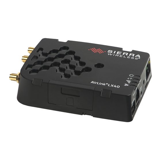
Introduction to the LX40 Description (See Connect the Antennas page 18.) Cellular Antenna Connector Wi-Fi Antenna Connector* Diversity Antenna Connector LEDs (See LED Behavior on page 31.) *Wi-Fi model Grounding screw RJ-45 Ethernet Port (See page 14.) Power Connector USB 2.0 Micro-AB Port (See Ethernet on page 39.) -
Page 10: Sample Power Consumption Scenarios
The following items come with the LX40 router: • DC power cable • Quick Start Guide The following items can be ordered separately from Sierra Wireless: • Universal AC power adapter (part number 2000579) · Voltage input: 100–240 VAC · Current output: 1.5 A Rev. -
Page 11: Warranty
Introduction to the LX40 Warranty The LX40 comes with a 3-year warranty, and has an optional 2-year warranty extension. Rev. 2 January 2021 41112510... -
Page 12: Installation And Startup
2: Installation and Startup This chapter shows how to connect, install and start the AirLink LX40. It also describes the front panel LEDs, and I/O functionality. Note: Field wiring and connections in hazardous locations must be connected as per the wiring methods requirement for Class 2 circuits mentioned in the National Electric Code and the Canadian Electric Code. -
Page 13: Step 1-Insert The Sim Card
Installation and Startup The default ACEmanager password is printed on the device label. You should always Warning: change the default password after logging in to ACEmanager. However, if the unit must be reset to factory default settings, your custom password may also be reset to default (depending on the Reset Mode configured in ACEmanager). -
Page 14: Step 2-Mount And Ground The Lx40 Chassis
103 mm 4 1/16 in. Figure 2-2: Mounting and Grounding the LX40 Grounding the LX40 Sierra Wireless strongly recommends that you always ground the chassis using the grounding point shown in Figure 2-3. For DC installations (with a fixed “system” ground reference), Sierra Wireless recommends grounding the LX40 chassis to this system ground reference. -
Page 15: Flat Mount
Figure 2-3: Ground connector Flat Mount To mount the LX40 permanently to any surface or if you are mounting the LX40 on a DIN rail, order an LX40 mounting bracket kit (P/N 6001221) from Sierra Wireless. The kit contains: •... -
Page 16: Mounting In A High Vibration Environment
Figure 2-5: Attaching the LX40 to the bracket Mounting in a High Vibration Environment Note: If you are mounting the LX40 in a high vibration area, Sierra Wireless strongly recommends using two nylon cable ties to secure the LX40 on the bracket. -
Page 17: Din Rail Mount
Installation and Startup DIN Rail Mount You can mount the LX40 on a DIN rail in a vertical orientation, with the antenna connectors pointing up or down. Note: The DIN rail mounting clip should only be used on a horizontally-mounted DIN rail. Ensure spring clip is at the bottom To mount the LX40 with antenna... -
Page 18: Step 3-Connect The Antennas
Cellular antenna connector: Primary receive and transmit antenna connector • Cellular Diversity antenna connector: LTE MIMO and 3G Diversity The AirLink LX40 with Wi-Fi also has: • One reverse polarity SMA male connector for the Wi-Fi antenna. Sierra Wireless recommends cabling out the antenna. -
Page 19: Recommended Antenna Separation
Ethernet (RJ-45)—Use a Cat 5e or Cat 6 Ethernet cable Step 5—Connect the Power The AirLink LX40 comes with a 3 meter (10 ft.) DC power cable. You can also purchase an optional AC adapter. Rev. 2 January 2021 41112510... -
Page 20: Cable Strain Relief
The cable should not be taut and should not pull the power connector at an angle. Fusing For DC installations, Sierra Wireless recommends fusing the power input using a 4 A, fast blow fuse on the V line, recommended to have no more than ±10% de-rating over the operating temperature range. -
Page 21: Power Connector On The Lx40
Installation and Startup Power Connector on the LX40 Pin 4 (Green) Pin 3 (White) GPIO On/Off (Ignition) control Pin 1 (Red) For I/O information, Power page Pin 2 (Black) Ground For more information, see wiring diagrams on page Figure 2-8: DC Power Cable Connections (Colors indicate DC cable wire colors) Table 2-2: Power Connector Pin and DC Cable Wires Name DC Cable... -
Page 22: Wiring Diagrams
Pin 1 (Power) —Use the red wire in the DC cable to connect Pin 1 to the power source. Include a 4 A, fast blow fuse, recommended to have no more than ±10% de- rating over the operating temperature range, in the input power line. Sierra Wireless recommends using a continuous (unswitched) DC power source. - Page 23 Pin 1 (Power) —Use the red wire in the DC cable to connect Pin 1 to the power source. Include a 4 A, fast blow fuse, recommended to have no more than ±10% de- rating over the operating temperature range, in the input power line. Sierra Wireless recommends using a continuous (unswitched) DC power source.
-
Page 24: Step 6-I/O Configuration
AirLink LX40 Series Hardware User Guide Step 6—I/O Configuration You can use Pin 4 on the LX40 power connector for I/O configuration. Power Connector Figure 2-11: I/O Pin-out for the LX40 Power Connector You can use the I/O pin as: ·... - Page 25 Installation and Startup You can use the I/O pin in conjunction with events reporting to configure the LX40 to send a report when the state of the monitored router changes, for example when a switch is opened or closed. For more information, refer to the ALEOS Software Configuration User Guide (Events Reporting chapter).
- Page 26 AirLink LX40 Series Hardware User Guide Digital Input You can use the green wire to connect Pin 4 to a digital input to detect the state of a switch, or to monitor an external device such as a motion detector, a remote solar panel, or a remote camera.
- Page 27 Installation and Startup High Side Pull-up / Dry Contact Switch Input You can use the green wire to connect Pin 4 to a dry contact switch. The dry contact switch is not available in Standby mode. LX40 Internal pull-up resistor (10K) Pin 4 (power connector) On** = 1.1 mA (Typ)
- Page 28 AirLink LX40 Series Hardware User Guide LX40 Internal pull-up resistor Pin 4 (power connector) Off (default)* Protection Circuitry Output Off (default)* * Configurable on the ACEmanager I/O tab Solar panel or battery Figure 2-15: Analog Input Table 2-6: Analog Input...
- Page 29 Installation and Startup Low Side Current Sink Output You can use Pin 4 as a low side current sink; for example, to drive a relay. LX40 Internal pull-up resistor Protection External solenoid/relay circuit Circuitry = 500 mA (Typ)* Sink Pin 4 (power connector) * See Table 2-7 on page 29 for more details.
-
Page 30: Step 7-Check The Router Operation
0.5 V Step 7—Check the Router Operation 1. When power is supplied to the AirLink LX40 router, it powers up automatically, as indicated by the flashing LEDs. If it does not turn on, ensure that the: · Power connector is plugged in and supplying voltage greater than 9 VDC. -
Page 31: Led Behavior
Solid Amber Fair signal (equivalent to 2 bars) Flashing Amber Poor signal (equivalent to 1 bar) If possible, Sierra Wireless recommends moving the router to a location with a better signal. Flashing Red Inadequate (equivalent to 0 bars) Sierra Wireless recommends moving the router to a location with a better signal. -
Page 32: Ethernet Leds
AirLink LX40 Series Hardware User Guide Table 2-9: LED Behavior Color / Pattern Description Note: The quality of the signal strength is measured using the appropriate parameters for the radio technology in use. Network Solid Green Connected to an LTE network (using SIM card or R2C eSIM) -
Page 33: Step 8-Configure The Software
Installation and Startup Step 8—Configure the Software You can configure the ALEOS software on the LX40 using: • ACEmanager (browser-based application) • AirLink Management Service (cloud-based application) • AirLink Mobility Manager (unified software platform deployed in the enterprise data center) •... -
Page 34: Reboot The Lx40
If you require a network management solution deployed in your data center, contact your Sierra Wireless sales representative for a demonstration of the AMM capabilities. Configuring with AT Commands For a complete list of AT commands, refer to the ALEOS Software Configuration User Guide. -
Page 35: Recovery Mode
ID, network password, custom APNs, and low voltage standby are preserved by default. However, you can configure the LX40 Reset Mode to reset all values, including the user password. For more details, refer to the ALEOS Software Configuration User Guide for AirLink LX40 (Admin chapter). –Or– •... - Page 36 AirLink LX40 Series Hardware User Guide • Wait 10 minutes. If no action is taken within 10 minutes of the device entering Recovery mode (for example, if the Recovery screen has not been loaded by the web browser), it automatically reboots and exits Recovery mode.
-
Page 37: Specifications
3: Specifications This chapter describes the LX40 router specifications. Certification and Interoperability Note: All certifications listed below are pending. Some are in progress; others are planned. Emissions / Immunity • Industry Canada • Safety CB Scheme • UL 60950 • Industry Certification ISO7637-2 •... -
Page 38: Network Technology
AirLink LX40 Series Hardware User Guide Network Technology LTE and HSPA For a list of supported bands, see Table 3-4 on page 44 and Table 3-5 on page 44. Reliability MTBF calculations are performed per Telcordia “Reliability Prediction Procedure for Electronic Equipment”... -
Page 39: Host Interfaces
By default, the USB port is configured as a virtual Ethernet port. A Windows driver must be installed on the PC in order to support USB • use. The drivers are available for download on Sierra Wireless’ support web site: source.sierrawireless.com/resources/airlink/software_downloads/... -
Page 40: Sim Card Interface
AirLink LX40 Series Hardware User Guide SIM Card Interface The LX40 has one 6-pin SIM socket for a mini-SIM (2FF) SIM card, operated at 1.8 V/3.3 V. This interface is compliant with the applicable 3GPP standards for USIM. Mechanical Specifications... -
Page 41: Power Specifications
The device looks for a qualified voltage on this pin as part of the power up sequence. If it doesn’t see it, the device will not turn on. If you are using a Sierra Wireless AC power adapter, the connection is inside the cable. -
Page 42: Wi-Fi Performance
AirLink LX40 Series Hardware User Guide Wi-Fi Performance Technology Frequency MIMO 20 MHz 40 MHz 80 MHz 802.11n 2.4 GHz 1 × 1 72 Mbps 5 GHz 1 × 1 100 Mbps 150 Mbps 802.11ac 5 GHz 1 × 1... -
Page 43: Wi-Fi Antenna Gain
Wi-Fi Antenna Gain The AirLink LX40 is compliant with the RF exposure requirements at 20 cm separation distance specified in EN 62311:2008 and 1999/519/EC for mobile exposure conditions, provided the maximum antenna gain does not exceed the limits given in the table below. -
Page 44: Radio Frequency Bands
AirLink LX40 Series Hardware User Guide Radio Frequency Bands To determine which radio module your gateway has, refer to the label on the bottom of the gateway, or in ACEmanager, go to Status > About, and check the Radio Module Type field. - Page 45 Specifications Table 3-6: LX40 Radio Module WP7607 EMEA Radio Module Firmware Band Frequencies Technology Generic Band 1 Tx: 1920–1980 MHz Rx: 2110– 2170 MHz Band 3 Tx: 1710–1785 MHz Rx: 1805–1880 MHz Band 7 Tx: 2500–2570 MHz Rx: 2620–2690 MHz ...
- Page 46 AirLink LX40 Series Hardware User Guide Table 3-7: LX40 Radio Module WP7609 Australia and New Zealand Radio Module Firmware Band Frequencies Technology Generic Band 1 Tx: 1920–1980 MHz Rx: 2110– 2170 MHz Band 3 Tx: 1710–1785 MHz Rx: 1805–1880 MHz ...
- Page 47 Specifications Table 3-8: LX40 Radio Module WP7610 North America Radio Module Firmware Band Frequencies Technology Generic Band 2 Tx: 1850–1910 MHz Rx: 1930– 1990 MHz Band 4 Tx: 1710–1755 MHz Rx: 2110–2155 MHz Band 5 Tx: 824–849 MHz Rx: 869–894 MHz ...
- Page 48 AirLink LX40 Series Hardware User Guide Table 3-9: LX40 Radio Module WP7702 Worldwide Radio Module Firmware Band Frequencies Technology Generic Band 1 Tx: 1920–1980 MHz Rx: 2110– 2170 MHz Band 2 Tx: 1850–1910 MHz Rx: 1930– 1990 MHz ...
- Page 49 Specifications Table 3-9: LX40 Radio Module WP7702 Worldwide Radio Module Firmware Band Frequencies Technology Generic GSM/GPRS GSM 850 Tx: 824–849 MHz Rx: 869– 894 MHz E-GSM 900 Tx: 880–915 MHz Rx: 925–960 MHz DCS 1800 Tx: 1710–1785 MHz Rx: 1805–1880 MHz ...
-
Page 50: Radio Module Conducted Transmit Power
AirLink LX40 Series Hardware User Guide Radio Module Conducted Transmit Power The following tables provide radio module conducted transmit power specifications. The radio module type is printed on the label on the bottom of the router and is available in ACEmanager (Status >... - Page 51 Specifications Table 3-13: Radio Module WP7609 Conducted Transmit Power Band Conducted Tx Notes Power (dBm) Bands 1, 3, 5, 7, 8, 28 +23±1 Connectorized (Class 3) WCDMA Bands 1, 5, 8 +23±1 Connectorized (Class 3) Table 3-14: Radio Module WP7610 Conducted Transmit Power Band Conducted Tx Notes...
-
Page 52: Mechanical Specifications
AirLink LX40 Series Hardware User Guide Mechanical Specifications Front view 25 mm (1 in.) Weight: 135 g (4.8 oz.) Top view 79 mm (3 1/8 in.) 103 mm (4 1/16 in.) 111 mm (4 3/8 in.) Figure 3-1: LX40 Mechanical Specifications Rev. -
Page 53: Regulatory Information
Warning: could void the user's authority to operate this equipment. Les changements ou modifications de cet appareil non expressément Avertissement : approuvés par Sierra Wireless peuvent annuler le droit de l'utilisateur à utiliser cet équipement. Rev. 2 January 2021 41112510... -
Page 54: Rf Exposure
AirLink LX40 Series Hardware User Guide RF Exposure In accordance with FCC/IC requirements of human exposure to radio frequency fields, the radiating element shall be installed such that a minimum separation distance of 20 cm should be maintained from the antenna and the user's body. - Page 55 FCC ID/IC Number N7NWP76C 2417C-WP76C Device Frequency Band Maximum Antenna Gain (dBi) AirLink LX40 Must not exceed antenna gains due to RF exposure and ERP/EIRP limits, as listed in the module’s FCC grant. Table 4-4: WP7702 Antenna Gain Specifications FCC ID/IC Number...
- Page 56 AirLink LX40 Series Hardware User Guide WEEE Notice If you purchased your AirLink LX40 in Europe, please return it to your dealer or supplier at the end of its life. WEEE products may be recognized by their wheeled bin label on the product label.
-
Page 57: Accessories
A: Accessories DC Power Cable (Black Connector) Table A-1: DC Power Cable DC Power Cable Part Number 2000522 Product Release 2016 Components: 1 UL2464 20 AWG × 4 core cable 4 Molex female crimp terminals /AWG 20-24, 250V, 5 A max, phosphor bronze ... -
Page 58: Ac Power Adapter (Black Connector)
AirLink LX40 Series Hardware User Guide AC Power Adapter (Black Connector) Table A-2: AC Power Adapter AC Power Adapter Part Number 2000579 Product Release 2016 AC Power Adapter Input Table A-3: Input Specifications Minimum Typical Maximum Input Input Voltage 90 VAC 100–240 VAC... -
Page 59: Ac Power Adapter Environmental Specifications
AC Power Adapter Environmental Specifications Table A-5: AC Power Adapter Environmental Specifications Operating Operating Temperature 0°C ~ 40°C (operates normally) Relative Humidity 10% ~ 90% Altitude Sea level to 2,000 meters Vibration 1.0 mm, 10–55 Hz, 15 minutes per cycle for each axis (X, Y, Z) Non-operating Storage Temperature -30°C ~ 70°C... -
Page 60: Ac Power Adapter Hazardous Substances
AirLink LX40 Series Hardware User Guide AC Power Adapter Hazardous Substances • EU Directive 2011/65/EU “RoHS” • EU Directive 2012/19/EU “WEEE” • REACH AC Power Adapter Energy Efficiency The AC adapter complies with International Efficiency Levels, as shown in Table A-7. -
Page 61: Index
Index AC power adapter, specifications, 58 I / O Configuration, 24 Accessories, 10 I/O auxiliary connector, 24 ACEmanager, 33 Input AirLink Management Service, 33 Analog, 27 ALEOS software, 33 Dry contact switch, 27 AMM, 34 Ignition switch, 26 Analog input, 27 Installation Antenna Connect data... - Page 62 AirLink LX40 Series Hardware User Guide Reset to factory default settings, 34 exposure, 54 specifications, 18 Screw Torque, 40 Software, configure, 33 Specifications, 37 Environmental, 37 Regulatory, 59 RF, 18 Standards, regulatory, 59 Tools required for install, 12 Voltage, input and ripple...
Need help?
Do you have a question about the AirLink LX40 and is the answer not in the manual?
Questions and answers