Table of Contents
Advertisement
Quick Links
Advertisement
Table of Contents

Summary of Contents for AFM Workshop LS-AFM
- Page 1 LS-AFM Users Guide V 1.1 Part # 10-1121-16...
- Page 2 European Union CE Mark The presence of the CE Mark on AFM Workshop equipment means that it has been designed, tested and certified as complying with all applicable European Union (CE) regula- tions and recommendations.
-
Page 3: Table Of Contents
3.2.3.1. Tip Approach............3-11 3.2.3.2. Z Parameters............3-11 3.2.3.3. XYZ Calibration............3-11 3.2.3.4. XY Parameters............3-12 3.2.3.5. Other Controls............3-12 3.2.4. Force Distance Curves............3-13 3.3. Video-View Software................3-14 Measuring Images With the LS-AFM................4-1 4.1. Operating the Video Microscope.............4-1 4.2. Preparing Samples...................4-2 4.2.1 Exchanging Samples.............4-2 4.3. Exchanging Probes...................4-3 4.4. - Page 4 Selecting a Location................A-1 A.2. Setting Up the Optical Microscopes............A-1 A.2.1 Top View Optic................A-1 A.2.2 Inverted Optical Microscope...........A-2 A.3. Connecting the LS-AFM to the Cables...........A-3 A.4. System Check...................A-3 A.5. Aligning the Video Microscopes to the Cantilever........A-3 A.5.1 Aligning the Top View Optic...........A-3 A.5.2 Aligning the Inverted Microscope with the Cantilever..A-4...
-
Page 5: Introduction To Atomic Force Microscopy
For an in-depth description of AFM instrumentation, we recommend the book Atomic Force Microscopy by Peter Eaton and Paul West. This book provides a complete theoretical, as well as practical explanation for the design and application of AFMs. V 1.1 / LS-AFM Users Guide Section 1-1... -
Page 6: Introduction To The Ls-Afm
Introduction to the LS-AFM When fully assembled, the LS-AFM comprises four subunits. They are the control computer, the Ebox, the stage, and the video optical microscope. 2.1 Computer The control computer is a standard IBM/PC-type computer with a Microsoft Windows operating sys- tem. -
Page 7: Ebox
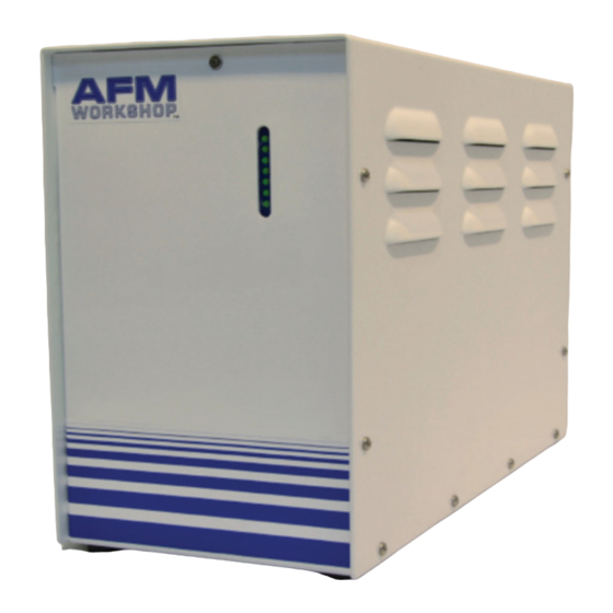
Ebox. Besides the cable to the stage, there is a plug for an auxiliary 50-pin cable that gives access to the Ebox's internal electronic signals. Front and back views of the LS-AFM Ebox showing indicator lights and connectors for ribbon cables and USB 2.4.1. -
Page 8: Software
3. Software The TT-2 AFM includes three separate software modules in the AFM Installation files: AFM Workshop Acquisition Software, Video Microscope Software, and Gwyddion Image Analysis Software. This installation guide is targeted towards a computer running Windows 3.1 Installation Procedure NOTE: If the target computer has a previous version of LabVIEW installed, it is imperative that it first be completely removed. -
Page 9: Afm-View Software
Changing the files used by the program is possible with the File buttons. These files may be edited to change parameters with a text editor such as Notepad. Appendix B lists the contents of both the configuration and scanner files. V 1.1 / LS-AFM Users Guide Section 3-2... -
Page 10: Modes
For optimal scanning, the amplitude should not exceed 2.5V or the resonance will become saturated (see section 5.4). Lower, Selected, and Upper Frequency: The lower, selected, and upper frequencies cor- respond to green, blue, and red vertical bars in the oscilloscope windows, respectively. V 1.1 / LS-AFM Users Guide Section 3-3... -
Page 11: Manual Z Motor Control
Range Check option. When started, the scanner is moved in a square pattern, which can be readily observed with the video opti- cal microscope. This function must be completed before beginning a scan. V 1.1 / LS-AFM Users Guide Section 3-4... -
Page 12: Automated Tip Approach
See section 6 for more information on high resolution scanning. 3.2.2 Topo Scan Window After the Pre-Scan functions are ready, the Topo Scan window is used for measuring AFM images. V 1.1 / LS-AFM Users Guide Section 3-5... -
Page 13: Image Window
Each of the win- dows is opened by clicking on S, H, or C; the window can be closed by re-clicking on the S, H, or C. V 1.1 / LS-AFM Users Guide Section 3-6... -
Page 14: Oscilloscope Window
3.2.2.2 Oscilloscope Window A Z vs. X position plot of the probe as it scans across a surface is plotted in two screens. The data plotted is selected in the Display window. V 1.1 / LS-AFM Users Guide Section 3-7... -
Page 15: Scan Setup
Gain: Scale factor for the feedback control signal. Proportional: Scale factor for the proportional term in the PID feedback controller. Integral: Scale factor for the integral term in the PID feedback controller. V 1.1 / LS-AFM Users Guide Section 3-8... -
Page 16: Display
Source of signals displayed in the “Display Left/Right” drop down boxes Z ERR Z DRIVE Z SENSE Setpoint Strain Gauge Z Piezo H.V. Amp Comparator GPID Non-Vibrating Signal Light Lever Photo-Detector Vibrating Signal Phase/Amplitude Demodulator Z AMP Z PHASE V 1.1 / LS-AFM Users Guide Section 3-9... -
Page 17: Tip Retract
Incorrect use of the system functions can damage the TT-2 AFM. System tab in vibrating mode System tab in non-vibrating mode V 1.1 / LS-AFM Users Guide Section 3-10... -
Page 18: Tip Approach
Scanner configu- ration file until the Exit button is pushed in the Topo Scan window. The user must have administrator rights in order to save the calibration values. V 1.1 / LS-AFM Users Guide Section 3-11... -
Page 19: Xy Parameters
Tip Approach motor jog: This function will appear in the Other Controls sub-window when the advanced tip approach options are not visible. Other Controls for vibrating mode Other Controls for non-vibrating mode V 1.1 / LS-AFM Users Guide Section 3-12... -
Page 20: Force Distance Curves
F/D curve. During this part of the curve, the probe is touching the sample surface. Rate: The rate or velocity of the sample as it is moved towards and away from the probe. V 1.1 / LS-AFM Users Guide Section 3-13... -
Page 21: Video-View Software
The quality of the image viewed with the video microscope depends directly on the reflectiv- ity of the sample being viewed. Therefore, it is not possible to give instructions for optimizing the video microscope images. It is recommended that operators experiment to find the best parameters. V 1.1 / LS-AFM Users Guide Section 3-14... -
Page 22: Measuring Images With The Ls-Afm
4. Measuring Images With the LS-AFM Once the LS-AFM is assembled, users can expect to take a few hours to learn how to mea- sure images. It is very important to learn how to: Operate the video microscope. Prepare samples. -
Page 23: Preparing Samples
Samples can be prepared on glass slides or on petri dishes. It is critical that the samples are properly adhered to the slides/dishes, to avoid additional vibrations. 4.2.1 Exchanging Samples Follow the steps below to successfully exchange samples with the LS-AFM. Raise the Z motor until the probe is at least ¼″ from the sample’s surface. -
Page 24: Exchanging Probes
NOTE: If the probe holder does not sit completely level with the probe exchange mechanism, it is possible to adjust to the screws on the bottom of the exchange tool to achieve the desired height. V 1.1 / LS-AFM Users Guide Section 4-3... -
Page 25: Aligning The Light Lever Force Sensor
Top + Bottom signal is maxi- mized while the Beam Position is mostly centered. V 1.1 / LS-AFM Users Guide Section 4-4... -
Page 26: Optically-Assisted Tip Approach
4.5 Optically-Assisted Tip Approach Tip approach with the LS-AFM is achieved using a woodpecker algorithm activated in the Pre-Scan window. To save time during tip approach, move the probe as close to the surface as possible before activating the Automatic Tip Approach function. The video microscope can prove very helpful for manual probe approach. -
Page 27: Contact Mode Imaging
Z range. Once true feedback has been achieved, open the Topo Scan tab at the top of the AFM Workshop window. V 1.1 / LS-AFM Users Guide Section 4-6... - Page 28 10,11 V 1.1 / LS-AFM Users Guide Section 4-7...
-
Page 29: Topo Scan Tab
S button to the right of the scan window. The H and C buttons allow the user to alter the histogram and color scheme of the scans, accordingly. When finished scanning, press Tip Retract. This function lightly releases the probe from the sample surface. V 1.1 / LS-AFM Users Guide Section 4-8... - Page 30 V 1.1 / LS-AFM Users Guide Section 4-9...
-
Page 31: Vibrating Mode Imaging
Use the Manual Z Motor Control to move the light lever towards the sample (see sec- tion 4.5.). Initiate Automated Tip Approach. Wait for the green light to indicate that feedback was achieved. V 1.1 / LS-AFM Users Guide Section 4-10... - Page 32 Z range. Once true feedback has been achieved, open the Topo Scan tab at the top of the AFM Workshop window. 11,12 V 1.1 / LS-AFM Users Guide Section 4-11...
-
Page 33: Topo Scan Tab
S button to the right of the scan window. The H and C buttons allow the user to alter the histogram and color scheme of the scans, accordingly. When finished scanning, press Tip Retract. This function lightly releases the probe from the sample surface. V 1.1 / LS-AFM Users Guide Section 4-12... - Page 34 V 1.1 / LS-AFM Users Guide Section 4-13...
-
Page 35: Troubleshooting
5. Troubleshooting – What Can Go Wrong When Measuring Images Although the operation of the LS-AFM is quite simple, some problems can occur while imag- ing samples. The following sections detail some of the most common problems that may occur. It is important to keep these potential problems in mind when operating the LS-AFM. -
Page 36: Resonance Saturated
(see section 4.6. j-k). 5.6 Defective Probe In the event that none of the above problems exist and it is not possible to get an image, the probe may be defective. V 1.1 / LS-AFM Users Guide Section 5-2... -
Page 37: High Resolution Imaging
6. High Resolution Imaging High resolution images are measureable with the LS-AFM. However, as with any AFM, obtaining those images requires that the AFM be optimally set up and that the operator knows the critical parameters for measuring high resolution images. The table below illus- trates the difficulty in measuring images as a function of the desired dimensions. - Page 38 The resolution of the scanner depends on the electronic noise in the control elec- tronics and the mechanical gain of the piezoelectric ceramics in the scanner. In the LS-AFM the electronic noise can be reduced by reducing the Gain on the high voltage amplifiers that drive the scanner piezolectric ceramics. The LS-AFM scanner has an XY mechanical gain of 3:1.
- Page 39 The AFM control software is designed to make a careful probe approach under manual control. This is achieved with the “Advanced Tip Approach” window under the Pre-Scan tab in conjunction with the “Tip Approach Parameters” window under the System tab. V 1.1 / LS-AFM Users Guide Section 6-3...
- Page 40 The magnitude of the initial “Z Amplitude” • Tip approach GPID parameters • Extend Factor • Retract Delta The initial value for the setpoint when feedback is established is the “Z Amplitude” multi- plied by the “Extend Factor.” V 1.1 / LS-AFM Users Guide Section 6-4...
-
Page 41: Appendix A: Setting U
A.2 Setting Up the Optical Microscopes A.2.1. Top View Optic The video optical microscope is essential for effi- cient operation of the LS-AFM. After setting up the microscope, we recommend spending some time learning to operate it by viewing some samples. -
Page 42: Inverted Optical Microscope
Increase the magnification with the zoom tube adjuster and increase the light intensity as needed. A.2.2. Inverted Optical Microscope The inverted microscope for the LS-AFM can come from two sources: Another Manufacturer - Follow the manufac- turer instructions for setting up the inverted microscope. -
Page 43: Connecting The Ls-Afm To The Cables
Move the micrometers on the video microscope XY translators to their central position. Move the micrometers on the LS-AFM stage to their central position. V 1.1 / LS-AFM Users Guide Appendix A-3... -
Page 44: Aligning The Inverted Microscope With The Cantilever
AFM stage until the probe is visible in the center of the inverted microscope image. NOTE: The micrometers will move the LS-AFM stage in one direction only. To move in the opposite direction, the user must manually push the stage. -
Page 45: First Alignment Of The Light Lever
Tighten the lock down screws located on the left and right side of the LS-AFM stage. See the picture below. A.6 First Alignment of the Light Lever This procedure assumes that the light lever was cor- rectly aligned at the factory or by an authorized agent. -
Page 46: Grounding The Ls-Afm
Modes/IO connec- tion on the back of the stage. A wire can be added to the ground connector to receive signals from the probe. V 1.1 / LS-AFM Users Guide Appendix A-6... -
Page 47: Parameter Files
Appendix B: LS-AFM Files The LS-AFM software has three separate files that it uses. The first is a parameter file which stores all of the parameters used for operating the microscope. The second is a scanner file, which is unique for each scanner and has range and calibration information. Finally, data files contain images measured by the microscope. -
Page 48: Scanner Files
The scanner file has the calibration and range information used by the AFM-View software. The contents of the file are: B.3 Data Files LS-AFM data files are stored in a text format. At the top of the data file are the parameters used for the scan. V 1.1 / LS-AFM Users Guide... -
Page 49: Appendix C: Calibratio
Appendix C: Calibration Calibration of the LS-AFM requires scanning a standard sample that has known X,Y and Z dimensions. If a sample with squares is used, the pitch in X and Y should be around 10 µm. The height of the features in Z should be around 100 nm. - Page 50 Using the “Measure Distances” feature on the bottom left-hand corner of the extracted profile, create vertical lines that bisect each square at approximately the same point. Insert the values in the “Length” column into each X Measures blanks in the calibra- tion software. V 1.1 / LS-AFM Users Guide Appendix C-2...
- Page 51 To calibrate Z, the user may either use the 0° or 90° scan. Extract a profile, and measure distances from the top of each square to the bottom of each pit. Enter the Height values in the Z Measures blanks in the calibration software. V 1.1 / LS-AFM Users Guide Appendix C-3...
- Page 52 Enter these values in the System tab and click “Save.” NOTE: To obtain the most accurate calibration values for the scanner, the user may have to complete multiple calibration iterations. V 1.1 / LS-AFM Users Guide Appendix C-4...
-
Page 53: Appendix D: Noise Flo
Level the image by pressing the “Level data by mean plane subtraction” button and the “Correct lines by matching height median” button. Find the noise value with the “Statistical Quantities” button, under Ra (Sa) for sur- face roughness. V 1.1 / LS-AFM Users Guide Appendix D-1... - Page 54 CAUTION: Increasing the Z HV Gain will increase the Z ceramic’s dynamic range, and will expand the Z ceramic (and probe) toward the sample. Make sure the tip is removed from the surface before increasing Z HV Gain. V 1.1 / LS-AFM Users Guide Appendix D-2...
-
Page 55: Appendix E: Probes
Resonance Frequency 150 – 350 kHz Length 225 – 450 micron Width 30 – 40 micron Thickness 0.1 - 0.5 micron Force Constant 0.1 – 0.5 N/M CM28-A probes from Applied Nanostructures recommended. V 1.1 / LS-AFM Users Guide Appendix E-1... -
Page 56: Appendix F: Technica
Appendix F: Technical Information This appendix has technical information that may be useful for creating customer instrumen- tation with the LS-AFM. Additional information is available in the LS-AFM technical guide. F.1 Electronic Block Diagrams V 1.1 / LS-AFM Users Guide... -
Page 57: Ebox And Modes Pin Assignments
F.2 Ebox and Modes Pin Assignments V 1.1 / LS-AFM Users Guide Appendix F-2... -
Page 58: Appendix G: Optimizin
When first learning to operate an AFM, it is helpful to scan a reference sample in 2D and adjust the GPID settings to see the effect on the Z voltage and the Z error signal, as shown in the figure below. V 1.1 / LS-AFM Users Guide Appendix G-1... -
Page 59: Appendix H: Renamin
There should only be one green device, corresponding with the DAQ card in the user’s Ebox. c. Rename the only remaining green device as Dev1. This can be accomplished by right-clicking on the device and selecting Rename. V 1.1 / LS-AFM Users Guide Appendix H-1... -
Page 60: Appendix I: Analyzing Force/Distance Curves
T-B signal as the sample is directly pushing against the probe. This is labeled slope data in the first figure above. The force constant for the cantilever is supplied by the manufacturer. V 1.1 / LS-AFM Users Guide Appendix I-1... - Page 61 The spring constant for TM190-A probes in 40 N/m. Thus, to calculate the adhesion force from the data in the figure above: Fad = ((1.03-.85 v) / (.05 v/nm)) * 40 nN/nm = 7.2 nN V 1.1 / LS-AFM Users Guide Appendix I-2...
-
Page 62: Appendix I: Inverted Optical Microscope
Otherwise, the focusing mechanism may be damaged. J.1.2 Stage Before transporting the stage, fix the flexible knobs with pieces of adhesive tape so that they will not move. V 1.1 / LS-AFM Users Guide Appendix J-1... - Page 63 J.2 Module Nomenclature This diagram illustrates all of the components provided with the AFMWorkshop inverted microscope. Items required for fluorescence microscopy are not shown here but are provided. V 1.1 / LS-AFM Users Guide Appendix J-2...
- Page 64 J.3.3 Attaching the Fixator of the Universal Handwheel This is an optional piece, which may be attached according to user demand. Join the fixator to the stage and to the connecting rod with hexagonal screws. V 1.1 / LS-AFM Users Guide Appendix J-3...
- Page 65 J.3.6 Connecting the Cables Turn the main power supply switch to “O” (OFF). Connect the plug of the lamp housing or illumination column to the connector. Connect the manual controller. V 1.1 / LS-AFM Users Guide Appendix J-4...
- Page 66 NOTE: After the illumination has been ignited, the filter will be very hot. Allow the filter holder and filters to cool before replacing them. Engage each filter in the light path by moving the filter holder in the direction of the arrow. V 1.1 / LS-AFM Users Guide Appendix J-5...
- Page 67 Select the light path with the light path selec- tor lever. The lever allows the user to switch between eyepiece observation and video cam- era viewing. Place a specimen on the stage. Engage the 10X objective in the light path. V 1.1 / LS-AFM Users Guide Appendix J-6...
- Page 68 While looking through the right eyepiece, adjust the coarse/ fine adjustment knobs to bring the specimen into focus. e. Adjust the aperture iris. f. Insert the filters. g. Begin observation. V 1.1 / LS-AFM Users Guide Appendix J-7...
- Page 69 Adjust the interpupillary distance and diopter. Engage the appropriate objective and bring the specimen into focus. Adjust the aperture iris and field iris diaphragms. Engage the required filters. Adjust the brightness. Begin observation. V 1.1 / LS-AFM Users Guide Appendix J-8...
- Page 70 Rotate the condenser axial adjustment knob to focus the light. Adjust the mercury lamp to center on the viewing field. Rotate the condenser axial adjustment knob to illuminate the viewing field evenly. V 1.1 / LS-AFM Users Guide Appendix J-9...
- Page 71 V 1.1 / LS-AFM Users Guide Appendix J-10...
- Page 72 If problems occur, please review the following list and take remedial action as indicated. If you cannot solve the problem after checking the entire list, please contact your local representative for assistance. V 1.1 / LS-AFM Users Guide Appendix J-11...
- Page 73 V 1.1 / LS-AFM Users Guide Appendix J-12...
- Page 74 Push in gently. If an excessive force is applied or the bulb is twisted, the bulb may be damaged. To reattach the lamp socket, insert the plug into the socket and push the guide pins gently into the guide holes. V 1.1 / LS-AFM Users Guide Appendix J-13...
- Page 75 Loosen the two screws on the mercury lamp, and exchange the old lamp with the new. Tighten the two screws on the new mercury lamp, and put the unit back in the holder, V 1.1 / LS-AFM Users Guide Appendix J-14...
- Page 76 Clean plastic surfaces with clear water. When not using the microscope, set the main switch to Off, confirm that the lamp housing is cool, and cover the microscope with the provided dust cover. V 1.1 / LS-AFM Users Guide Appendix J-15...