Table of Contents
Advertisement
Quick Links
Operation-Repair-Parts
Electric High Pressure
Airless Sprayer
Electric high pressure sprayer packages for application of protective coatings.
For professional use only.
Not approved for use in explosive atmospheres or hazardous locations.
Important Safety Instructions
Read all warnings and instructions in this
manual. Save these instructions.
For Model Information and maximum working pressure,
see page 2.
333208F
EN
Advertisement
Table of Contents

Related Manuals for Graco e-Xtreme Z25


Summary of Contents for Graco e-Xtreme Z25
- Page 1 Operation-Repair-Parts Electric High Pressure 333208F Airless Sprayer Electric high pressure sprayer packages for application of protective coatings. For professional use only. Not approved for use in explosive atmospheres or hazardous locations. Important Safety Instructions Read all warnings and instructions in this manual.
-
Page 2: Table Of Contents
California Proposition 65 ......27 Graco Standard Warranty ......28... -
Page 3: Warnings
Warnings Warnings The following warnings are for the setup, use, grounding, maintenance, and repair of this equipment. The exclamation point symbol alerts you to a general warning and the hazard symbols refer to procedure-specific risks. When these symbols appear in the body of this manual or on warning labels, refer back to these Warnings. Product-specific hazard symbols and warnings not covered in this section may appear throughout the body of this manual where applicable. - Page 4 Warnings WARNING SKIN INJECTION HAZARD High-pressure fluid from gun, hose leaks, or ruptured components will pierce skin. This may look like just a cut, but it is a serious injury that can result in amputation. Get immediate surgical treatment. • Do not spray without tip guard and trigger guard installed.
-
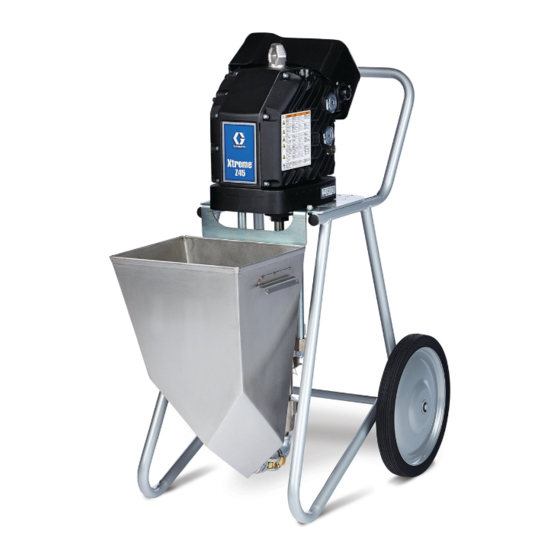
Page 5: Component Identification - Cart Mount
Component Identification - Cart Mount Component Identification - Cart Mount Electric Driver G Junction Box Cover Lower Pressure Adjustment Knob Fluid Drain/Purge Valve Outlet Check Valve Packing Nut Red Indicator Light Power Switch Oil Fill Cap (Vented) Fluid Outlet Junction Box . -
Page 6: Installation
Installation Installation 2. Bring cord to unit and remove two screws to separate junction box cover (G) and power switch (E) from remainder of sprayer. See F . 3. Improper wiring may cause electric shock or other serious injury. All electrical wiring must be done by a qualified electrician and comply with all local codes and regulations. - Page 7 Installation 5. Attach ground wire to ground terminal inside 7. Replace junction box screws and washers removed junction box (S). in step 2 and tighten cord grip to securely hold power cord in junction box (S). See F . 6. NOTE: The power cord attaches to a separate ground screw than the ground screw that is already attached.
-
Page 8: Grounding
Installation Grounding Install Vented Oil Cap Before Using Equipment The driver gear-box is shipped from the factory prefilled with oil. The temporary unvented cap (PX) prevents oil The equipment must be grounded to reduce the risk leaks during shipment. This temporary cap must be of static sparking and electric shock. -
Page 9: Setup
Setup Setup NOTICE The minimum hose size allowable is 3/8 in. ID x 50 ft (10 mm x 15 m). Smaller hoses can cause high To avoid tip over, make sure cart is on a flat and level pressure spikes and result in damage to the sprayer. surface. -
Page 10: Pressure Relief Procedure
Pressure Relief Procedure Pressure Relief Procedure 5. Hold gun firmly against a grounded metal pail. Trigger the gun. Follow the Pressure Relief Procedure whenever you see this symbol. ti8252a This equipment stays pressurized until pressure is 6. Engage gun trigger lock. manually relieved. -
Page 11: Prime/Flush
Prime/Flush Prime/Flush 7. If priming, equipment is now ready to spray (proceed to Spray, page 12). If flushing, proceed with step 8. To avoid injury from splashing, always flush at lowest NOTE: The remaining steps are for flushing only. possible pressure. NOTICE 1. -
Page 12: Spray
Spray Spray 6. Disengage gun trigger lock. NOTICE Do not allow pump to run dry. It will quickly accelerate to a high speed causing damage. 1. Perform Prime procedure, page 11. ti5048b 7. Spray a test pattern. Read fluid manufacturer’s 2. -
Page 13: Maintenance
2. Reinstall the oil drain plug. Torque to 18-23 ft-lb (25-30 N•m). 3. Open the fill cap (P) and add Graco Part 16W645 ISO 220 silicone-free synthetic EP gear oil. Check . 8: Sight Glass and Oil Fill Cap the oil level in the sight glass (K). -
Page 14: Corrosion Protection
Maintenance Corrosion Protection Cart Maintenance Always flush the pump before fluid dries on the Periodically lubricate the axle between points A and B displacement rod. Never leave water or water-based with lightweight oil. See the following figure. fluid in the pump overnight. First, flush with water or a compatible solvent, then with a rust inhibitor, such as mineral spirits. -
Page 15: Troubleshooting
Troubleshooting Troubleshooting NOTE: Check all possible remedies before disassembling pump. NOTE: The LED on the driver will blink if an error is detected. Problem Cause Solution Pump output low on both Inadequate power supply. See Power Supply, page 6. strokes Exhausted fluid supply. - Page 16 Driver does not turn over Over voltage (greater than 300 V) Check power supply and LED is off No power to control board Contact your Graco distributor or Tech Service for more information. Driver does not turn over Encoder fault Cycle power.
-
Page 17: Error Codes
Verify that outlet check valve is installed on pump and functions properly. NOTE: A faulty outlet check valve can result in excessive pump speed and cause high voltage internally to the electric driver. Deviation Low Temperature • Warm equipment. • Contact your Graco distributor or Tech Service for more information. 333208F... - Page 18 Cycle power and check status indicator to see if error is still active. • Calibrate the encoder (see driver manual). • Contact your Graco distributor or Tech Service for more information. Alarm Encoder Error • Cycle power and check the status indicator to see if the error is still active.
-
Page 19: Repair
Repair Repair Disconnect and Reconnect Lower To prevent skin injection and splashing, never open a camlock hose or applicator fitting while there is pres- sure in the fluid line. Perform Pressure Relief Proce- dure, page 10, before performing any repair 1. - Page 20 Repair 6. Remove clip (11) and slide coupling cover (13) up to 8. Refer to Xtreme Lower manual (311762) to service remove coupling (12). lower. 9. Reconnect lower by following disconnect steps in reverse order. NOTE: Torque nuts (10) to 50-60 ft-lb (68-81 N•m). 7.
-
Page 21: Outlet Check Valves
Repair Outlet Check Valves 6. Use a wrench to loosen the outlet check valve, then remove the outlet check valve from the pump lower. NOTE: The pressure drain valve may remain attached to the outlet check valve housing during 1. Perform Pressure Relief Procedure, page 10, and repair if needed. -
Page 22: Parts
Parts Parts Sprayer Models 24Y452, 24Y317, 25A829 Models 24W315, 24W316, 24Y317 25A829 only Models 24X450, 24Y452, 24W315, 24Y317 only 333208F... -
Page 23: Parts List - Sprayer
Parts Parts List - Sprayer Ref. Part Description Qty. Ref. Part Description Qty. 55‡ VALVE, outlet check 262914 CART, painted, mortar, light wt 17B509 GASKET, cover, junction box 116406 WHEEL, semi pneu, light weight TAG, oil 113436 RING, retaining 17A411 LABEL, instructions 24V016 DRIVER, non-hazardous location 162505 FITTING, union, swivel 100133 WASHER, lock, 3/8... -
Page 24: Outlet Check Valve
Parts Outlet Check Valve Parts List - Outlet Check Valve Part Specifications: Ref. Instruction Ref. Part Description Qty. Torque to 101-108 N•m (75-80 ft-lb) 127882 NUT, seat (includes 4) 102595 PACKING, o-ring Apply lubricant 181492 GUIDE, ball 102972 BALL, metallic Accessories: 17A091 HOUSING, ball, check... -
Page 25: Dimensions
Dimensions Dimensions Driver Dimensions A height 50.0 in (1.27 m) B depth 33.5 in (0.85 m) C width 28.0 in (0.71 m) 333208F... -
Page 26: Technical Specifications
Sound pressure 74 dB at maximum cycle rate Oil capacity 1.0-1.2 quarts 0.9-1.1 liters Oil specification Graco part number 16W645 ISO 220 silicone-free synthetic EP gear oil Inlet/Outlet Sizes Fluid inlet size 1-1/4 npt(m) Fluid outlet size 3/8 npt(m) -
Page 27: California Proposition 65
California Proposition 65 California Proposition 65 CALIFORNIA RESIDENTS WARNING: Cancer and reproductive harm – www.P65warnings.ca.gov. 333208F... -
Page 28: Graco Standard Warranty
With the exception of any special, extended, or limited warranty published by Graco, Graco will, for a period of twelve months from the date of sale, repair or replace any part of the equipment determined by Graco to be defective.
Need help?
Do you have a question about the e-Xtreme Z25 and is the answer not in the manual?
Questions and answers