Table of Contents
Advertisement
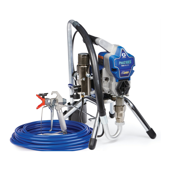
Operation, Parts
210 ES Electric
Airless Sprayers
For professional use only.
Not approved for use in explosive atmospheres or hazardous locations.
For portable airless spraying of architectural paints and coatings.
Models: 17D163, 17C305
3000 psi (207 bar, 20.7 MPa) Maximum Working Pressure
Important Safety Instructions
Read all warnings and instructions in this manual and
related manuals. Be familiar with the controls and the
proper usage of the equipment. Save these instructions.
Related Manuals
Gun – 312830 (SG3)
Use only genuine Graco replacement parts.
The use of non-Graco replacement parts may void warranty.
Pump – 334599
17D163
Scan QR code or click on link for
operational video.
http://magnum.graco.com/pro210es
ti25464a
17C305
334659G
EN
Advertisement
Table of Contents

Related Manuals for Graco Pro210ES


Summary of Contents for Graco Pro210ES
- Page 1 Save these instructions. Related Manuals Scan QR code or click on link for Gun – 312830 (SG3) Pump – 334599 operational video. http://magnum.graco.com/pro210es ti25464a 17D163 17C305 Use only genuine Graco replacement parts. The use of non-Graco replacement parts may void warranty.
-
Page 2: Table Of Contents
Technical Specifications ........39 Graco Standard Warranty ........40 Graco Information . -
Page 3: Warnings
Warnings Warnings The following warnings are for the setup, use, grounding, maintenance, and repair of this equipment. The exclamation point symbol alerts you to a general warning and the hazard symbols refer to procedure-specific risks. When these symbols appear in the body of this manual or on warning labels, refer back to these Warnings. - Page 4 Use Graco conductive or grounded high-pressure airless paint sprayer hoses. •...
- Page 5 • Check hoses and parts for signs of damage. Replace any damaged hoses or parts. • This system is capable of producing 3000 psi. Use Graco replacement parts or accessories that are rated a minimum of 3000 psi. • Always engage the trigger lock when not spraying. Verify the trigger lock is functioning properly.
- Page 6 Warnings ELECTRIC SHOCK HAZARD This equipment must be grounded. Improper grounding, setup, or usage of the system can cause electric shock. • Turn off and disconnect power cord before servicing equipment. • Connect only to grounded electrical outlets. • Use only 3-wire extension cords. •...
-
Page 7: Component Identification
Component Identification Component Identification Stand Model ti25254a M Drain Tube ON/OFF Switch Fluid Intake Pressure Control Pump Prime Valve Fluid Outlet Tip Guard Power Cord Wrap Spray Tip Filter Finger Guard / TSL Fill Point Airless Hose Model/Serial Tag (Not shown, located Power Cord on bottom of unit.) Trigger Lock... -
Page 8: Hi-Boy Models
Component Identification Hi-Boy Models ti25465a M Drain Tube ON/OFF Switch Fluid Intake Pressure Control Pump Prime Valve Fluid Outlet Tip Guard Hanger Spray Tip Filter Finger Guard / TSL Fill Point Airless Hose Pail Hook Power Cord Model/Serial Tag (Not shown, located Trigger Lock on bottom of unit.) 334659G... -
Page 9: Grounding
Grounding Grounding The equipment must be grounded to reduce the risk of static sparking and electric shock. An electric or static spark can cause fumes to ignite or explode. An improper ground can cause electric shock. A good ground provides an escape wire for the electric current. -
Page 10: Pressure Relief Procedure
Pressure Relief Procedure Pressure Relief Procedure Turn pressure control to the lowest Follow the Pressure Relief setting. Disengage the trigger lock. Procedure whenever you see this symbol. This equipment stays pressurized until pressure is manually relieved. To help prevent serious injury from pressurized fluid, such as skin injection, splashed fluid ti25230a and moving parts, follow the Pressure... - Page 11 Pressure Relief Procedure Turn the prime valve down. Put drain VERY SLOWLY loosen the tip guard retaining nut or the hose end tube in a pail. Leave prime valve in the coupling to relieve pressure down (drain) position until you are ready gradually.
-
Page 12: Setup
When unpacking sprayer for the first time or after long term storage perform setup procedure. When first setup is performed remove shipping plug from fluid outlet. Connect Graco airless hose to fluid ti25199a outlet. Use wrenches to tighten securely. Use wrenches to tighten securely. - Page 13 Setup When unpacking sprayer for the first time remove packaging materials from inlet strainer. After long term storage check inlet strainer for clogs and debris. ti24639a Make certain ON/OFF switch is OFF. ti24638a Fill throat packing nut with TSL to ti25130a prevent premature packing wear.
- Page 14 Setup 10. Turn prime valve down. 14. Increase pressure 1/2 turn to start motor. Allow fluid to flush through sprayer for one minute. 15. Turn prime valve horizontal. Disengage trigger lock. ti25200a 16. Hold a metal part of the gun firmly to a grounded metal pail.
-
Page 15: Startup
Startup Startup Increase pressure 1/2 turn to start motor. Allow paint to circulate through sprayer until paint flows out the drain tube. Perform Pressure Relief Procedure, page 10. Turn pressure control to lowest pressure. ti25231a Turn prime valve horizontal. Disengage trigger lock. - Page 16 Startup Hold gun against grounded metal waste pail. Trigger gun until paint appears. 20 s ti25202a 10. Screw tip assembly onto gun and tighten. See Spray Tip Installation, page 17. For gun assembly instructions, see separate gun manual. ti24647a Move gun to paint pail and trigger for 20 seconds.
-
Page 17: Operation
Operation Operation Spray Tip Installation 3. Screw assembly onto gun. Tighten. 1. Perform Pressure Relief Procedure, page 10. 2. Use spray tip (A) to insert ™ OneSeal (B) into tip guard (C). ti24652a Spray Spray test pattern. Adjust pressure to eliminate heavy edges. -
Page 18: Clear Tip Clog
Operation Hold gun perpendicular, 10-12 in. (25-30 cm) from surface. Spray back and forth; overlap by 50%. ti25206a ti24673a Engage trigger lock. Return Spray Tip to Trigger gun after moving. Release original position. Disengage trigger lock trigger before stopping. For additional and continue spraying. -
Page 19: Cleanup
Operation Cleanup Perform Pressure Relief Procedure, page 10. Remove tip guard and Spray Tip. For additional information, see separate gun manual. ti24709a Place fluid intake in flushing fluid. Use water for water base paint and mineral spirits for oil-based paint. Place drain tube in waste pail. - Page 20 Operation Increase pressure 1/2 turn to start motor. Hold gun against paint pail. Disengage trigger lock. Trigger gun and increase pressure until the pump runs steady and flushing fluid appears. ti24713a Raise fluid intake above flushing fluid. ti24712a ti25232a Stop triggering gun. Move gun to waste pail, hold gun against pail, trigger gun to thoroughly flush system.
- Page 21 Operation 10. Turn prime valve horizontal. Trigger gun into flushing pail to purge fluid from hose. 11. Engage trigger lock. ti24718a 14. If flushing with water, flush again with mineral spirits or Pump Armor to leave a protective coating to prevent freezing or corrosion.
-
Page 22: Maintenance
Maintenance Maintenance Routine maintenance is important to ensure proper operation of your sprayer. Maintenance includes performing routine actions which keep your sprayer in operation and prevents trouble in the future. Activity Interval Inspect/clean sprayer filter, fluid inlet strainer, and gun filter. Daily or each time you spray Inspect motor shield vents for blockage. -
Page 23: Troubleshooting
Troubleshooting Troubleshooting Mechanical/Fluid Flow Follow Pressure Relief Procedure, Check all possible problems and causes page 10, before checking or repairing. before disassembling the unit. What to Check What to Do If check is OK, go to next When check is not OK, Problem check refer to this column... - Page 24 Troubleshooting What to Check What to Do If check is OK, go to next When check is not OK, Problem check refer to this column Pump output is low Pump rod damage. Repair pump. See pump manual. Low stall pressure. Turn pressure knob fully clockwise.
- Page 25 Troubleshooting What to Check What to Do If check is OK, go to next When check is not OK, Problem check refer to this column Fluid is spitting from gun Air in pump or hose. Check and tighten all fluid connections.
-
Page 26: Electrical
Troubleshooting Electrical Turn the ON/OFF switch OFF wait 30 seconds and then turn power back ON again (this ensures sprayer is in normal Symptom: Sprayer does not run, stops run mode). running, or will not shut off. Turn pressure control knob clockwise 1/2 turn. - Page 27 Troubleshooting Problem What to Check How to check Check motor rotation. Perform a spin test by connecting a 9 –12 Volt battery to the motor leads. Motor leads may vary in style and size. Locate the two wires going to the carbon brushes normally Red and Black.
- Page 28 Troubleshooting Problem What to Check How to check Check motor armature resistance. Connect the Red and Black leads from the motor to an Ohm meter. Rotate the motor while checking for opens. If an open is found replace the motor. BLACK (-) RED (+) YELLOW...
- Page 29 Troubleshooting Problem What to Check How to check Sprayer will not shut off after reaching Check pressure control. Disconnect pressure control, if or exceeding maximum pressure. sprayer still runs, replace control board. If the sprayer stops, replace pressure control. Basic electrical problems Motor leads are securely fastened Replace loose terminals;...
-
Page 30: Stand Model Sprayer Parts
Stand Model Sprayer Parts Stand Model Sprayer Parts Ref. Torque 140-160 in-lb (15.8 - 18.1 N•m) 30-35 in-lb (3.4 - 4.0 N•m) 18-23 in-lb (2.0 - 2.6 N•m) See page 36. From ti24099a ti25303a 334659G... - Page 31 Stand Model Sprayer Parts Ref. Torque 140-160 in-lb (15.8 - 18.1 N•m) Hammer tight 18-23 in-lb (2.0 - 2.6 N•m) ti25255a 334659G...
-
Page 32: Stand Model Parts List
Stand Model Sprayer Parts Stand Model Parts List Ref. Part Description Qty. Ref. Part Description Qty. 17C795 FAN, motor, roller, 115498 SCREW, mch, slot/hex, clutch includes 54b, wash hd 54c, 54d 117501 SCREW, mach, slot NUT, push hex wash hd WASHER, shim, round 117559 O-RING... -
Page 33: Hi-Boy Sprayers Parts
Hi-Boy Sprayers Parts Hi-Boy Sprayers Parts Ref. Torque 140-160 in-lb (15.8 - 18.1 N•m) 30-35 in-lb (3.4 - 4.0 N•m) 23-27 in-lb (2.6 - 3.1 N•m) See page 36 ti25461a 334659G... - Page 34 Hi-Boy Sprayers Parts Ref. Torque 140-160 in-lb (15.8 - 18.1 N•m) Hammer tight 18-23 in-lb (2.0 - 2.6 N•m) ti25462a 334659G...
-
Page 35: Hi-Boy Sprayers Parts List
Hi-Boy Sprayers Parts Hi-Boy Sprayers Parts List Ref. Part Description Qty. Ref. Part Description Qty. 54 * 17C794 KIT, motor, electric 107434 WASHER, bronze includes 54a 115498 SCREW, mch, 54a 17C795 FAN, motor, roller, slot/hex, wash hd clutch includes 54b, 116073 WASHER, steel 54c, 54d... -
Page 36: Control Box And Filter
Control Box and Filter Control Box and Filter Ref. Torque 140-160 in-lb (15.8 - 18.1 N•m) 30-35 in-lb (3.4 - 4.0 N•m) 130-150 in-lb (14.7 - 16.9 N•m) 48-72 in-lb (5.4 - 8.1 N•m) ti25463a 334659G... -
Page 37: Control And Filter Parts List
Control Box and Filter Control and Filter Parts List Ref. Part Description Qty. Ref. Part Description Qty. 15E022 SEAT, valve 104361 PACKING, o-ring 187625 HANDLE, valve, drain 111600 PIN, grooved 239914 VALVE, drain, includes 277364 GASKET, seat, valve 4, 5, 26 117501 SCREW, mach, hex 224807... -
Page 38: Wiring Diagram
Wiring Diagram Wiring Diagram from Motor Red (+) 2 x Yellow Black (-) Replaceable Fuse Pressure Control Assembly ON/OFF Switch ti5643a Black Capacitor Power White Plug Green ti5643a 334659G... -
Page 39: Technical Specifications
Technical Specifications Technical Specifications 17D163, 17C305 Metric Sprayer Maximum fluid working pressure 3000 psi 207 bar, 20.7 MPa Maximum Delivery 0.47 gpm 1.8 lpm Maximum Tip Size 0.021 0.021 Fluid Outlet npsm 1/4 in. 1/4 in. Cycles 700 per gallon 185 per liter Generator Minimum 3000 W... -
Page 40: Graco Standard Warranty
Graco’s written recommendations. This warranty does not cover, and Graco shall not be liable for general wear and tear, or any malfunction, damage or wear caused by faulty installation, misapplication, abrasion, corrosion, inadequate or improper maintenance, negligence, accident, tampering, or substitution of non-Graco component parts. -
Page 41: Graco Information
For the latest information about Graco products, visit www.graco.com. For patent information, see www.graco.com/patents. TO PLACE AN ORDER, contact your Graco distributor or call 1-800-690-2894 to identify the nearest distributor. All written and visual data contained in this document reflects the latest product information available at the time of publication.
Need help?
Do you have a question about the Pro210ES and is the answer not in the manual?
Questions and answers