Graco APX 5200 Operation, Parts

Graco APX 5200 Operation, Parts

Apx electric texture sprayers

Advertisement

Quick Links

Operation, Parts
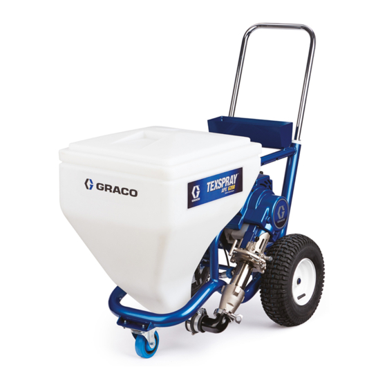
APX Electric Texture
Sprayers
For portable airless spraying of water-based materials only.
For professional use only.
Not approved for use in explosive atmosphere or hazardous locations.
Models: APX 5200, APX 6200 and APX 8200
See page 2 for model information, including maximum working pressure and approvals.
Important Safety Instructions
Read all warnings and instructions in this manual and related manuals.
Be familiar with the controls and the proper usage of the equipment.
Save these instructions.
Gun – 309495 (APX 6200 & 8200)
Gun – 308491 (APX 5200)
Related Manuals
Pump – 332922
www.graco.com/techsupport
3A4442F
EN
ti29970a

Advertisement

Table of Contents
loading

Summary of Contents for Graco APX 5200

  • Page 1 For portable airless spraying of water-based materials only. For professional use only. Not approved for use in explosive atmosphere or hazardous locations. Models: APX 5200, APX 6200 and APX 8200 See page 2 for model information, including maximum working pressure and approvals. Important Safety Instructions Read all warnings and instructions in this manual and related manuals.
  • Page 2: Table Of Contents

    Graco Standard Warranty ........
  • Page 3: Warnings

    Warnings Warnings The following warnings are for the setup, use, grounding, maintenance, and repair of this equipment. The exclamation point symbol alerts you to a general warning and the hazard symbols refer to procedure-specific risks. When these symbols appear in the body of this manual or on warning labels, refer back to these Warnings.
  • Page 4 Check hoses and parts for signs of damage. Replace any damaged hoses or parts. • This system is capable of producing 3000 psi (207 bar, 20.7 MPa). Use Graco replacement parts or accessories that are rated a minimum of 3000 psi (207 bar, 20.7 MPa).
  • Page 5 Do not kink or over-bend the material or air hose. • Do not expose the hose to temperatures or to pressures in excess of those specified by Graco. • Do not use the hose as a strength member to pull or lift the equipment.
  • Page 6 Warnings MOVING PARTS HAZARD Moving parts can pinch, cut, or amputate fingers and other body parts. • Keep clear of moving parts. • Do not operate equipment with protective guards or covers removed. • Pressurized equipment can start without warning. Before checking, moving, or servicing equipment, follow the Pressure Relief Procedure and disconnect all power sources.
  • Page 7: Component Identification

    Component Identification Component Identification ti29971a K VIBRA-FLO Hopper Shaker A Smart Control (6200/8200 models) B ON/OFF Switch L Amp Switch C Pressure Control M Hopper with cover D VIBRA-FLO™ ON/OFF Switch N Hopper Strainer (6200/8200 models) P Trigger Lock E VIBRA-FLO Control R Hose (6200/8200 models) S Bag Roller (Optional)
  • Page 8: Preparation

    Preparation Preparation ProGuard The ProGuard protects the sprayer against high and low voltage spikes. If the sprayer is Grounding plugged into a power source that goes too low or too high the sprayer stops operating. VIBRA-FLO Shaker (6200/8200 models) The equipment must be grounded to reduce the risk of static sparking and The hopper shaker vibrates the hopper which electric shock.
  • Page 9 Preparation Premix Slowly add water to a 5 gallon (18.9 liter) bucket of premix. ti30766a Make certain all dry powder clumps are mixed throughly before pouring mixture PREMIX into the sprayer hopper. NOTICE ti2493b Failure to make certain that all dry powder is throughly mixed may cause tip or pump Agitate to mix with mixing paddle, to a clogging.
  • Page 10: Pressure Relief Procedure

    Preparation Pressure Relief Procedure Engage trigger lock. Always engage the trigger lock when sprayer is stopped to prevent the gun from being triggered Follow the Pressure Relief accidentally by hand or if dropped or Procedure whenever you see this bumped. symbol.
  • Page 11: Setup

    Use wrenches to tighten securely. debris from entering the pump. Connect whip hose (if applicable) and Fill throat packing nut with Graco TSL to gun to other end of hose. Apply thread prevent premature packing wear. Do this sealant and tighten securely.
  • Page 12 Secure bag roller mounting frame to sprayer. • Place roller assembly on the mounting frame. • On the APX 5200/6200 models position the bag roller assembly in the lower position. • On the APX 8200 model position the bag roller assembly in the upper position.
  • Page 13: Start Up

    Start Up Start Up Increase pressure 1/2 turn to start motor and allow fluid to circulate through drain tube for 15 seconds; turn pressure down. Perform the start up procedure each time the sprayer is started for the first time after it has been cleaned or stored.
  • Page 14 Start Up Prime Pump Hold gun against grounded metal flushing pail. Trigger gun and increase fluid pressure 1/2 turn. Flush 1 minute. Prime the pump before placing the hopper filter into the hopper. Add 1-2 gallons (4-8 liters) of material to the hopper.
  • Page 15 Start Up 10. Trigger gun again into flushing pail until material appears. Move gun to hopper and trigger for 20 seconds. 00:20 ti30004a 11. Engage trigger lock. Assemble tip and guard, see Spray Tip Installation, page ti29985a VIBRA-FLO Shaker Adjustment (6200/8200 models) The hopper shaker speed is adjusted by adjusting the VIBRA-FLO knob on the...
  • Page 16 Start Up Shaker Armature/Coil Adjustment The hopper shaker is shipped with the gap preset for the best performance. If the armature and coil is replaced or needs adjustment, use a feeler gauge to adjust shaker gap. Set gap to 0.042 – 0.052 inch (1.06 –...
  • Page 17: Operation

    Operation Operation Spray Tip Installation Spray tip must be pushed all the way into the tip guard. Turn spray tip to push down. Turn the arrow shaped handle on the spray tip forward to the spray position. Perform Pressure Relief Procedure, page 10.
  • Page 18: Clear Tip Clog

    Operation Clear Tip Clog NOTE: If spray tip is difficult to rotate when turning to the unclog position perform, Pressure Relief Procedure, page 10, then turn Prime/Spray valve to spray position and repeat step 1. Engage trigger lock. Rotate spray tip To avoid serious injury from skin injection do not back to spray position.
  • Page 19 Operation ProGuard Error Codes This sprayer protects itself against high and low voltage. One of three error codes is displayed if the supply voltage is out of range. Error Code Definition Multiple incoming voltage surges detected - unplug sprayer and locate good voltage supply to prevent damage to electronics.
  • Page 20 Operation Change Display Units Press and hold to reset to zero. NOTE: JOB scrolls past, then the Press and hold DTS button for 5 seconds to number of gallons sprayed above 400 psi change pressure units (psi, bar, MPa) to (28 bar, 2.8 MPa) displays.
  • Page 21 Short press to move to SOFTWARE REV. ti29981a Short press DTS button. MOTOR ID RESISTOR scrolls by and model code SERIAL NUMBER scrolls past and then number (see below). serial number (e.g. 00001) displays. Motor ID Number Models APX 5200/6200 APX 8200 ti22720b 3A4442F...
  • Page 22 Operation Cleanup Move gun to waste pail, hold gun against pail, trigger gun to thoroughly flush system. Release trigger and engage trigger lock. Perform Pressure Relief Procedure, page 10. Remove tip guard and Spray Tip. For additional information, see separate gun ti30008a manual.
  • Page 23 Operation Add flushing fluid to the hopper and run 11. If flushing with water flush again with sprayer until the hopper is empty. Turn Pump Armor, to leave a protective ON/OFF switch to the OFF position. coating to prevent freezing or corrosion. ti30010a 10.
  • Page 24: Troubleshooting

    Troubleshooting Troubleshooting Mechanical/Fluid Flow Follow Pressure Relief Procedure, page 10, before checking or repairing. Check all possible problems and causes before disassembling unit. Problem Cause Solution CODE XX is displayed. Fault condition exists Determine fault correction from table, page 27. Pump output is low Spray tip worn Follow Pressure Relief Procedure...
  • Page 25 Troubleshooting Problem Cause Solution Pump output is low Pump rod damage Repair pump. See pump manual. Low stall pressure Turn pressure knob fully clockwise. Make sure pressure control knob is properly installed to allow full clockwise position. If problem persists, replace pressure transducer.
  • Page 26 Troubleshooting Problem Cause Solution Pump is difficult to prime Air in pump or hose Check and tighten all fluid connections. Cycle pump as slowly as possible during priming. Intake valve or piston valve is stuck Clean intake and piston valve. Be or leaking sure ball seat is not nicked or worn and that ball seats well.
  • Page 27 Troubleshooting Electrical Symptom: Sprayer does not run, stops Turn pressure control knob clockwise running, or will not shut off. 1/2 turn. View digital display. Perform Pressure Relief Procedure, page Keep clear of electrical and moving parts during troubleshooting procedures. To avoid electrical shock hazards when Plug sprayer into correct voltage, covers are removed for troubleshooting,...
  • Page 28 Troubleshooting Problem What to Check How to check Sprayer does not run at all Check transducer or transducer 1.Make sure there is no pressure in the system (see Pressure Relief connections Display shows CODE 02 Procedure, page ). Check fluid path for clogs.
  • Page 29 Troubleshooting Problem What to Check How to check Sprayer does not run at all Check transducer or transducer 1.Set sprayer to OFF and disconnect power to sprayer. connections (control board is not Display shows CODE 03 detecting a pressure signal). 2.Check transducer and connections to control board.
  • Page 30 Troubleshooting Problem What to Check How to check Sprayer does not run at all Control is commanding motor to 1.Remove pump and try to run sprayer. If motor runs, check for run but motor shaft does not rotate. Display shows CODE 05 locked or frozen pump or drive train.
  • Page 31 7.Check Motor Thermal Switch: board, or motor amp draw is Unplug thermal wires. Set meter to excessive. ohms. Meter should read the proper resistance for each unit (see table below). ti13140a Resistance Table: APX 5200/ 6.2k ohms 6200 APX 8200 10.0k ohms 3A4442F...
  • Page 32 Check Motor Thermal Switch: Unplug thermal wires. Set meter to ohms. Meter should read the proper resistance for each unit (see table below). ti13140a Resistance Table: APX 5200/ 6.2k ohms 6200 APX 8200 10.0k ohms Reconnect thermal device connector to control board socket.
  • Page 33 Troubleshooting Problem What to Check How to check Sprayer does not run at all Check to see if control board is 1.Make sure motor air intake is not blocked. over heating. Display shows CODE 10 2.Make sure fan has not failed. 3.Make sure control board is properly connected to back plate and that conductive thermal paste is used on...
  • Page 34 Troubleshooting Problem What to Check How to check Sprayer does not run at all Check voltage supply to the 1.Set sprayer to OFF and disconnect power to sprayer. sprayer (plugged into wrong Display shows CODE 17 voltage) 2.Locate a good voltage supply to avoid damage to electronics.
  • Page 35 Troubleshooting Sprayer Will Not Run (See following page for steps) Remove control box cover. Turn sprayer ON. Observe control board status light on control board (see page 28). See Step 1. Do See Step 2. Do No light you have over you have over Repair or 100 VAC (220...
  • Page 36 Troubleshooting STEP 1: STEP 2: 200-240V 200-240V Plug power cord Plug power cord in and turn switch in and turn switch ON. Connect ON. Connect probes to on/off probes to on/off switch. Turn switch. Turn meter to AC volts meter to AC volts STEP 4: STEP 3: Plug power cord...
  • Page 37 Troubleshooting Troubleshooting Procedure Plumb pressure gauge into material Mechanical problem: See the proper hose, plug sprayer in, and turn power fluid pump manual for the sprayer for switch ON. Does sprayer reach or further trouble shooting procedures exceed its maximum pressure? Unplug the transducer from control Replace the control board.
  • Page 38: Apx Cart Parts

    APX Cart Parts APX Cart Parts Ref. Torque Ref. Torque 70-80 in-lb (7.9 - 9.0 N•m) 200-230 in-lb (22.6 - 26 N•m) 25-30 ft-lb (33.9 - 40.1 N•m) 30-35 in-lb (3.4 - 3.9 N•m) 22-28 in-lb (2.5 - 3.2 N•m) 170-190 in-lb (19.2 - 21.5 N•m) 3A4442F...
  • Page 39 ASSEMBLY, hopper 111800 SCREW, cap hex 17P817 APX 6200, 17 gal. head (26.5L) includes 123 17S013 BOX, control, 17P818 APX 5200/8200, 25 shaker, (APX gal. (94.6L) includes 6200/8200) See page 45 for parts. FILTER, hopper 102 LABEL, warning 17R160 #6...
  • Page 40: Apx Pump And Motor Parts

    APX Pump and Motor Parts APX Pump and Motor Parts 119a 119b 48 50 26 ref ti30594b Ref. Torque Ref. Torque 190-210 in-lb (21.5 - 23.7 N•m) 9-11 in-lb (1.1 - 1.2 N•m) 25-30 ft-lb (33.9 - 40.1 N•m) 90-110 in-lb (10.2 - 12.4 N•m) 22-28 in-lb (2.5 - 3.2 N•m) 3A4442F...
  • Page 41 APX 8200 258909 APX 8200 114699 WASHER, thrust KIT, drive, housing, WASHER, lock repair 106115 APX 5200/6200 287295 APX 5200 includes 112600 APX 8200 47, 49 SCREW, cap SH 24M417 APX 6200 includes 114666 APX 5200/6200 47, 49 112599 APX 8200...
  • Page 42: Apx Control And Manifold Parts

    APX Control and Manifold Parts APX Control and Manifold Parts 40ref 28 65 133ref 77ref 87ref 98ref 26 ref 98 ref 98 ref 88 ref ti30614b Ref. Torque Ref. Torque 2-3 in-lb (0.23 - 0.34 N•m) 40-45 in-lb (4.5 - 5.1 N•m) 15-25 in-lb (1.7 - 2.8 N•m) 10-15 in-lb (1.1 - 1.7 N•m) 190-210 in-lb (21.5 - 23.7 N•m)
  • Page 43 Ref. Part Description Qty. 17A242 CORDSET, adapter, 17R029 BOARD, control Australia (APX 6200/8200) 15D530 APX 5200, U.K. includes 25, 28, 40, 63, 65, 72, 76,82 253103 Italy/Denmark/ Switzerland 17S871 BOARD, control (APX 5200) includes 114391 SCREW, grounding 25, 28, 40, 63, 65, 72,...
  • Page 44: Apx Vibra-Flo Shaker Parts

    APX VIBRA-FLO Shaker Parts APX VIBRA-FLO Shaker Parts APX 6200/8200 ti30597a Ref. Torque Ref. Torque 170-190 in-lb (19.2 - 21.5 N•m) 80-100 in-lb (9.0 - 11.2 N•m) Ref. Part Description Qty. Ref. Part Description Qty. 110755 WASHER, flat 17N609 PLATE, shaker 17P261 CLAMP, loop, 17N607 BRACKET, mounting, cushioned...
  • Page 45: Apx Vibra-Flo Shaker Control Parts

    APX VIBRA-FLO Shaker Control Parts APX VIBRA-FLO Shaker Control Parts APX 6200/8200 ti30596a Ref. Torque Ref. Torque 10-15 in-lb (1.1 - 1.7 N•m) 40-45 in-lb (4.5 - 5.1 N•m) 22-28 in-lb (2.5 - 3.2 N•m) 30-35 in-lb (3.4 - 3.9 N•m) Ref.
  • Page 46: Wiring Diagrams

    Wiring Diagrams Wiring Diagrams APX 5200 AMP SWITCH LED DISPLAY POTENTIOMETER PRESSURE TRANSDUCER BLUE BLACK FILTER JUMPER WIRE ON/OFF MOTOR THERMAL SWITCH SWITCH LEADS MOTOR SENSOR LEADS MOTOR BLUE FERRITE BROWN POWER PLUG ti32340a 3A4442F...
  • Page 47: Wiring Diagrams

    Wiring Diagrams Wiring Diagrams APX 6200/8200 AMP SWITCH LED DISPLAY POTENTIOMETER SHAKER CONTROL BOX PRESSURE TRANSDUCER BLUE BROWN BLACK BLUE FILTER 8200 ONLY MOTOR LEADS ON/OFF FILTER THERMAL SWITCH SWITCH COIL MOTOR SENSOR LEADS MOTOR BROWN BLUE BLUE BROWN GREEN/GROUND POWER PLUG ti30615a Shaker Control Box...
  • Page 48: Technical Specifications

    Technical Specifications Technical Specifications APX 5200 Metric Sprayer Maximum fluid working pressure 3000 psi 20.7 MPa, 207 bar Maximum Delivery 1.35 gpm 5.1 lpm Maximum Tip size 0.039 in. 0.099 cm Fluid Outlet npsm 1/2 in. 1.27 cm Cycles 110 per gallon...
  • Page 49 Technical Specifications APX 6200 Metric Sprayer Maximum fluid working pressure 3000 psi 20.7 MPa, 207 bar Maximum Delivery 1.58 gpm 6.0 lpm Maximum Tip size 0.041 in. 0.104cm Fluid Outlet npsm 1/2 in. 1.27 cm Cycles 97 per gallon 26 per liter Generator minimum 5000 W 5000 W...
  • Page 50 Technical Specifications APX 8200 Metric Sprayer Maximum fluid working pressure 3000 psi 20.7 MPa, 207 bar Maximum Delivery 2.1 gpm 8.0 lpm Maximum Tip size 0.045 in. 0.114 cm Fluid Outlet npsm 1/2 in. 1.27 cm Cycles 70 per gallon 19 per liter Generator minimum 5000 W...
  • Page 51: Graco Standard Warranty

    Graco’s written recommendations. This warranty does not cover, and Graco shall not be liable for general wear and tear, or any malfunction, damage or wear caused by faulty installation, misapplication, abrasion, corrosion, inadequate or improper maintenance, negligence, accident, tampering, or substitution of non-Graco component parts.
  • Page 52 For the latest information about Graco products, visit www.graco.com. For patent information, see www.graco.com/patents. TO PLACE AN ORDER, contact your Graco distributor or call 1-800-690-2894 to identify the nearest distributor. All written and visual data contained in this document reflects the latest product information available at the time of publication.

This manual is also suitable for:

Apx 6200Apx 8200309495308491332922

Table of Contents