Table of Contents
Advertisement
Operation
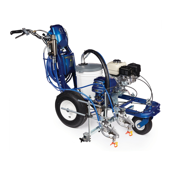
™
LineLazer
Standard Series and High Production (HP) Auto Series
For the application of line striping materials.
For professional use only.
For outdoor use only.
Not for use in explosive atmospheres or hazardous locations.
Maximum Operating Pressure: 3300 psi (22.8 MPa, 228 bar)
Important Safety Instructions
Read all warnings and instructions in this manual and in related manuals.
Be familiar with the controls and the proper usage of the equipment.
Save these instructions.
Related Manuals:
3A3389
Parts
311254
Gun
309277
Pump
3A3428
Auto-Layout Applications Methods
Use only genuine Graco replacement parts.
The use of non-Graco replacement parts may void warranty.
V 3900, 5900 Airless Line Stripers
ti27920a
3A3388A
EN
Advertisement
Table of Contents


Need help?
Do you have a question about the LineLazer v 3900 and is the answer not in the manual?
Questions and answers