Table of Contents
Advertisement
Quick Links
Instructions
e-Xtreme
High Pressure Airless Sprayers
Electric high pressure sprayer packages for application of protective coatings.
For professional use only.
Not approved for use in explosive atmospheres or hazardous locations.
See page 2 for Models information and Agency
approvals.
Important Safety Instructions
Read all warnings and instructions in this
manual and in your e-Xtreme Driver
manual before using the equipment.
Save all instructions.
®
Z60
3A6917A
EN
Advertisement
Table of Contents
Troubleshooting

Related Manuals for Graco e-Xtreme Z60


Summary of Contents for Graco e-Xtreme Z60
- Page 1 Instructions ® e-Xtreme 3A6917A High Pressure Airless Sprayers Electric high pressure sprayer packages for application of protective coatings. For professional use only. Not approved for use in explosive atmospheres or hazardous locations. See page 2 for Models information and Agency approvals.
-
Page 2: Table Of Contents
Maintenance ....... . 14 Graco Standard Warranty ..... 28 Preventative Maintenance Schedule . -
Page 3: Warnings
Warnings Warnings The following warnings are for the setup, use, grounding, maintenance, and repair of this equipment. The exclamation point symbol alerts you to a general warning and the hazard symbols refer to procedure-specific risks. When these symbols appear in the body of this manual or on warning labels, refer back to these Warnings. Product-specific hazard symbols and warnings not covered in this section may appear throughout the body of this manual where applicable. - Page 4 Warnings WARNING SKIN INJECTION HAZARD High-pressure fluid from gun, hose leaks, or ruptured components will pierce skin. This may look like just a cut, but it is a serious injury that can result in amputation. Get immediate surgical treatment. • Do not spray without tip guard and trigger guard installed.
- Page 5 Warnings WARNING PERSONAL PROTECTIVE EQUIPMENT Wear appropriate protective equipment when in the work area to help prevent serious injury, including eye injury, hearing loss, inhalation of toxic fumes, and burns. Protective equipment includes but is not limited to: • Protective eyewear, and hearing protection. •...
-
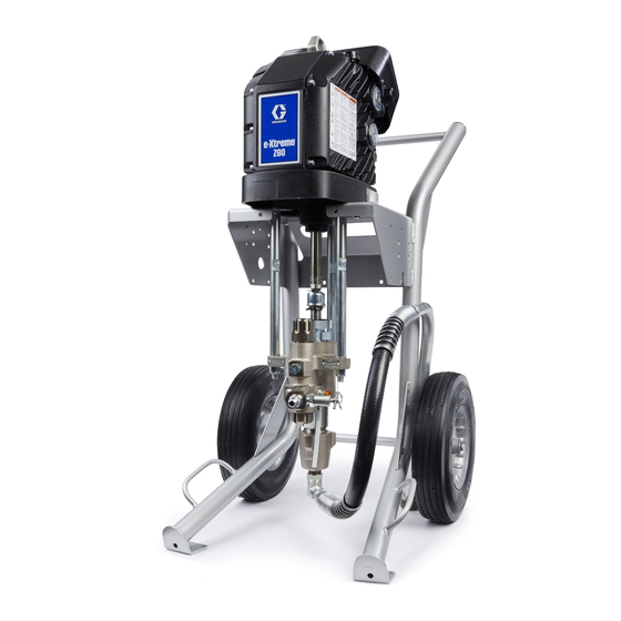
Page 6: Component Identification
Component Identification Component Identification Ref. Description Ref. Description Outlet Check Valve Electric Driver Status Indicator Light (LED) Pump Lower Oil Fill Cap (vented) Fluid Drain/Purge Valve Junction Box Packing Nut Filter Cap (models with integrated filter only) Power Switch Material Suction Hose Fluid Outlet Junction Box Cover NOTE: See your e-Xtreme Driver manual for warning... -
Page 7: Installation
Grounding wires and clamps for pails (Graco part 244524 - not supplied) Power Supply • Two 5 gallon (19 liter) metal pails (Graco part See your driver manual for instructions for power supply 101108 - not supplied) requirements. 1. Connect the ground wire (Y) to a ground stud on the Connect Power Supply back of the motor. -
Page 8: Install Vented Oil Cap Before Using Equipment
Setup Install Vented Oil Cap Before 2. Turn power switch (E) OFF. Connect unit to power source. Using Equipment The driver gear box is shipped from the factory pre-filled with oil. The temporary unvented cap (PX) prevents oil leaks during shipment. This temporary cap must be replaced with the vented oil cap (P) before use. - Page 9 6. Attach the material suction hose (U) to the pump 7. Check oil level. lower. NOTICE Only use oil with Graco part number 16W645. Any other oil may not lubricate properly and can cause damage to the drive train. 8. Always flush and prime the sprayer before each use (see Prime/Flush, page 11).
-
Page 10: Pressure Relief Procedure
Setup Pressure Relief Procedure 4. Disengage the gun trigger lock. Follow the Pressure Relief Procedure whenever you see this symbol. 5. Hold gun firmly against a grounded metal pail. Trigger the gun. This equipment stays pressurized until pressure is manually relieved. To help prevent serious injury from pressurized fluid, such as skin injection, splashing fluid and moving parts, follow the Pressure Relief Procedure when you stop spraying and before... -
Page 11: Trigger Lock
Setup Trigger Lock 4. Close the drain valve. Always engage the trigger lock when you stop spraying to prevent the gun from being triggered accidentally by hand or if dropped or bumped. Prime/Flush 5. Turn power switch (E) ON. 6. Prime or flush the hose or gun: a. - Page 12 Setup 7. If priming, equipment is now ready to spray 12. Turn power switch (E) OFF. (proceed to Spray, page 15). If flushing, proceed 13. Check the pump and gun filters. with step 8. NOTE: The remaining steps are for flushing only. NOTICE Do not prime pump through drain/purge valve using two component materials.
-
Page 13: Spray
Spray Spray 6. Disengage the gun trigger lock. NOTICE 7. Spray a test pattern. Read fluid manufacturer recommendations and adjust as necessary. Do not allow pump to run dry. It will quickly accelerate to a high speed causing damage. 1. Follow the Prime/Flush on page 11. 2. -
Page 14: Shutdown
Never leave water or water-based fluid in pump over night. If water-base fluid has been used, flush with 3. Open the oil fill cap (P) and add Graco Part No. water first, then with a rust inhibitor (such as mineral 16W645 silicone-free ISO 220 synthetic EP gear oil. -
Page 15: Check Oil Level
If oil is low, open the fill cap fluid in the pump overnight. First, flush with water or a (P) and add Graco Part No. 16W645 silicone-free ISO compatible solvent, then with a rust inhibitor, such as 220 synthetic EP gear oil. -
Page 16: Troubleshooting
Troubleshooting Troubleshooting NOTE: Check all possible remedies before disassembling the pump. NOTE: The status indicator (L) on the driver will blink if an error is detected. Problem Cause Solution Pump output low on both Exhausted fluid supply Refill and prime the pump. strokes * Clogged fluid outlet line, Clear the hose, outlet check valve, or gun;... - Page 17 Encoder fault Cycle power. Recalibrate the encoder following the and LED is on procedure listed in the e-Xtreme Driver Operation/Repair manual. Contact your Graco distributor or Tech Service for more information. Oil is leaking Oil was over filled Drain and refill oil as stated in Check Oil level, page 15.
-
Page 18: Error Code Troubleshooting
Troubleshooting Error Code Troubleshooting turning the power switch (E) to the OFF position for at least 30 seconds before turning back ON. Error codes can take two forms: Standby Mode • Alarm: Alerts you to the cause of the alarm and When slow blinking is displayed, the driver has entered shuts down the driver. - Page 19 Follow the calibration procedure listed in the e-Xtreme Driver Operation/Repair manual to calibrate the encoder (this code will blink if calibration is in progress). • Contact your Graco distributor or Tech Service for more information. Alarm Encoder Error • Cycle power and check the status indicator (L) to see if the error is still active.
-
Page 20: Repair
Repair Repair 6. Remove clip (11) and slide coupling cover (13) up to remove coupling (12). Xtreme Lower Removal Required Tools • Set of adjustable wrenches 7. Use a wrench to hold the tie rod flats to keep rods (8) from turning. Unscrew nuts (10) and remove the •... -
Page 21: Outlet Check Valves
Repair Outlet Check Valves 5. Use two wrenches to loosen the hose, then disconnect the hose from the outlet check valve housing. 1. Follow the Pressure Relief Procedure on page 10. 2. Disconnect the unit from the power source before removing or servicing the outlet check valve. -
Page 22: Parts
Parts Parts Torque to 145-155 ft-lb (196-210 N•m) Torque to 56-60 ft-lb (68-81 N•m) Apply thread locker. Apply grease lubricant. For information on Warning Labels, see your driver manual. 3A6917A... -
Page 23: Parts List
Parts Parts List Ref. Part Description Qty. - - - - - CART (see Cart Parts, page 24), Heavy Duty, Model 25P245 - - - - - CART (see Cart Parts, page 24), Light Weight, Model 25P246 4‡ 25P238 DRIVER, Z60 100133 WASHER, lock, 3/8 100101... -
Page 24: Cart Parts
Parts Cart Parts 17X355 - Heavy Duty Cart 17X356 - Light Weight Cart Ref. Part Description Qty. Ref. Part Description Qty. 113436 RING, retaining 154628 WASHER - - - - - CART, light weight 113436 RING, retaining 116406 WHEEL, semi-pneumatic 113361 CAP, tube, round 16W767 PLUG, tubing... -
Page 25: Outlet Check Valves Parts
Parts Outlet Check Valves Parts Parts Specifications: Outlet check Valves Parts List Ref. Instruction 25C189 (1/2 in. male npt inlet) Torque to 101-108 N•m (75-80 ft-lb) Ref. Part Description Qty. 25C190 NUT, seat (includes 2* and 4) Apply lubricant for 25C189 version 102595 PACKING, o-ring Accessories:... -
Page 26: Dimensions
Dimensions Dimensions Model Dimensions 25P245 25P246 Height 50.0 in. (1.27 m) 50.0 in. (1.27 m) Depth 30.0 in. (0.76 m) 31.5 in. (0.80 m) Width 26.0 in. (0.66 m) 28.0 in. (0.71 m) 3A6917A... -
Page 27: Technical Specifications
Minimum Recommended Generator Size 5 kW Oil Capacity 1.0 to 1.2 quarts 0.9 to 1.1 liters Oil Specification Graco part number 16W645 silicone-free ISO 220 synthetic EP gear oil Weight 25P245 (Heavy Duty Cart) 289 lb 131 kg 25P246 (Light Weight Cart) -
Page 28: Graco Standard Warranty
With the exception of any special, extended, or limited warranty published by Graco, Graco will, for a period of twelve months from the date of sale, repair or replace any part of the equipment determined by Graco to be defective.
Need help?
Do you have a question about the e-Xtreme Z60 and is the answer not in the manual?
Questions and answers