Graco Magnum X5 Repair And Parts Manual
Airless sprayers
Hide thumbs
Also See for Magnum X5:
- Owner's manual (56 pages) ,
- Repair and parts manual (52 pages) ,
- Operation manual (35 pages)
Table of Contents
Advertisement
Repair and Parts
™
™
X5
, X7
, ProX7
- For portable spray applications of architectural paints and coatings -
US Patent 6,752,067
European Patent 1 208 287
Korean Patent 10-0668583
X5 and X7 Models ONLY: Use water based or min-
eral-spirit type material only. Do not use materials having
flash points lower than 70°F (21°C). For more information
about your material request MSDS from distributor or
retailer.
ti11304a
Graco Inc. P.O. Box 1441 Minneapolis, MN 55440-1441
Copyright 2007, Graco Inc. is registered to I.S. EN ISO 9001
™
& ProX9
M
X5
AGNUM
Model: 262800
M
AGNUM
Model: 261815
ti9369a
™
Airless Sprayers
IMPORTANT SAFETY INSTRUCTIONS.
Read all warnings and instructions in this manual. Save
these instructions. See page 2 for model and series infor-
mation including dispense rate, recommended hose
length, guns, and maximum working pressure.
Related Manual:
M
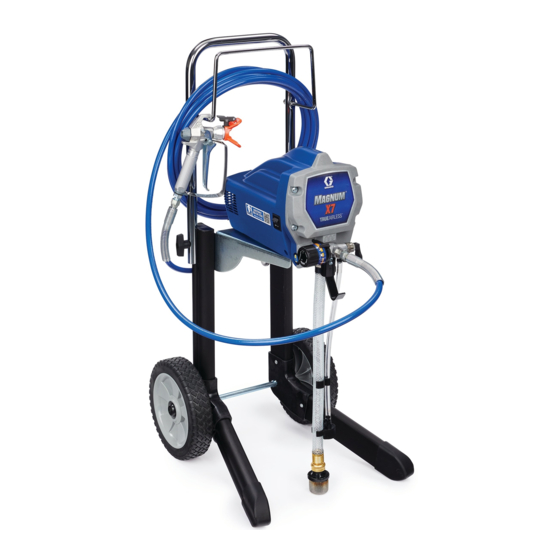
X7
AGNUM
Model: 262805
ti11305a
ProX7
Visit our website;
http://M
.Graco.com
AGNUM
312667B
(See specifications, page 2.)
M
ProX9
AGNUM
Model: 261820
ti9368a
Advertisement
Table of Contents
Troubleshooting

Related Manuals for Graco Magnum X5


Summary of Contents for Graco Magnum X5
- Page 1 MSDS from distributor or retailer. AGNUM AGNUM Model: 262800 Model: 262805 ti11304a ti11305a ProX7 ProX9 AGNUM AGNUM Model: 261815 Model: 261820 ti9369a ti9368a Graco Inc. P.O. Box 1441 Minneapolis, MN 55440-1441 Copyright 2007, Graco Inc. is registered to I.S. EN ISO 9001...
-
Page 2: Specifications
Specifications Specifications This equipment is not intended for use with flammable or combustible materials used in places such as cabinet shops or other “factory”, or fixed locations. If you intend to use this equipment in this type of application, you must comply with NFPA 33 and OSHA requirements for the use of flammable and combustible materials. - Page 3 Warnings Warnings The following warnings are for the setup, use, grounding, maintenance, and repair of this equipment. The exclama- tion point symbol alerts you to a general warning and the hazard symbols refer to procedure-specific risks. Refer back to these warnings. Additional, product specific warnings may be found throughout the body of this manual where applicable.
- Page 4 • Check hoses and parts for signs of damage. Replace any damaged hoses or parts. • This system is capable of producing 3000 psi. Use Graco replacement parts or accessories that are rated a minimum of 3000 psi. • Always engage the trigger lock when not spraying. Verify the trigger lock is functioning properly.
- Page 5 Do not kink or over-bend the hose. • Do not expose the hose to temperatures or to pressures in excess of those specified by Graco. • Do not use the hose as a strength member to pull or lift the equipment.
-
Page 6: Thermal Overload
Installation Installation Grounding and Electric Fluid supply container: follow local code. Requirements Solvent pails used when flushing: follow local code. Use only conductive metal pails, placed on a grounded surface such as concrete. Do not place the pail on a nonconductive surface, such as paper or cardboard, which interrupts grounding continuity. -
Page 7: Component Identification
Component Identification Component Identification Airless spray gun Sprays fluid. Power switch Turns sprayer ON and OFF. Increases (clockwise) and decreases (counter-clockwise) fluid pres- Pressure control knob sure in pump, hose, and spray gun. To select function, align symbol on pressure control knob with setting Setting Indicator indicator, page 9. - Page 8 Component Identification ti9724a ti9346a ti9670a ti9368a ti9669a (SG20) (SG10) ti9667a ti9668a ti11455a 312667B...
-
Page 9: Pressure Relief Procedure
Operation Operation Pressure Relief Procedure See Operation manual 312001 for basic information on Follow this Pressure Relief Procedure whenever you sprayer set-up, flushing, and storage. stop spraying and before cleaning, checking, servicing, or transporting equipment. Trigger Lock 1. Turn power switch OFF and unplug Always engage the trigger lock when you stop spraying power cord. -
Page 10: General Repair Information
General Repair Information General Repair Information To reduce risk of serious injury, including electric shock: • Do not touch moving or electric pars with fingers or tools while testing repair. Flammable materials spilled on hot, bare, motor • Unplug sprayer when power is not required for test- could cause fire or explosion. -
Page 11: Basic Troubleshooting
Basic Troubleshooting Basic Troubleshooting Check everything in this Basic Troubleshooting table before you bring the sprayer to a Graco/M authorized ser- AGNUM vice center. Problem Cause Solution Power switch is on and sprayer is Pressure is set at zero pressure. - Page 12 AutoPrime may need replacement. Turn power switch ON and listen for “tap” in pump. If you do not hear “tap”, AutoPrime is damaged. Take sprayer to Graco/M autho- AGNUM rized service center. Inlet valve check ball or seat is dirty Remove inlet fitting.
- Page 13 Check suction tube for cracks and cuts. Make sure suction tube clamp is on hose. Replace suction tube if cracked or damaged. Prime/Spray Valve is worn or Take sprayer to Graco/M AGNUM obstructed with debris. authorized service center. Pump check ball is stuck.
- Page 14 Basic Troubleshooting Problem Cause Solution Pressure is set at maximum but Spray tip is clogged. Unclog spray tip, see Operation cannot achieve a good spray pattern. manual 312001. Reversible spray tip is in UNCLOG Rotate arrow-shaped handle on position. spray tip so it points forward on gun. Spray tip is too large for sprayer.
- Page 15 Basic Troubleshooting Problem Cause Solution Fan pattern varies dramatically while Pressure control switch is worn and Take sprayer to Graco/M AGNUM spraying. causing excessive pressure variation. authorized service center. Sprayer does not turn on promptly when resuming spraying. Cannot trigger spray gun.
-
Page 16: Advanced Troubleshooting
Advanced Troubleshooting Advanced Troubleshooting See Basic Troubleshooting first, page 11 for problems that are more easily remedied. General Problem: Motor Does Not Operate Specific Problem Cause Solution Power switch is on and sprayer See Basic Troubleshooting, is plugged in; pump does not page 11. - Page 17 Advanced Troubleshooting Specific Problem Cause Solution Basic electrical problems. Motor overheated. Allow motor to cool for 45 minutes. Retry. Electrical outlet is damaged. Reset building circuit breaker or replace fuse. Try another outlet. Check electric supply with volt meter. Meter must read 85 to 130V AC.
- Page 18 Advanced Troubleshooting Specific Problem Cause Solution Sprayer Wiring Problems Sprayer power cord damaged. Unplug sprayer power cord. Disconnect black power cord wire at power switch. NOTE: Remove enclosure mounting screws and pull Unplug in-line connection white cord wire. enclosure away from drive Plug in power cord.
- Page 19 Advanced Troubleshooting General Problem: Circuit Breaker is Tripping Specific Problem Cause Solution Building circuit breaker opens Sprayer electrical wiring is Repair or replace any damaged wiring or as soon as sprayer is turned pinched or insulation is terminals. Securely reconnect wires. damaged.
- Page 20 Advanced Troubleshooting General Problem: Erratic Motor Operation Specific Problem Cause Solution Sprayer quits after running for Building circuit is overloaded. Remove other loads from building circuit or find 5 to 10 minutes another circuit that has less load. See Grounding and Electric Requirements, page 6.
- Page 21 Advanced Troubleshooting General Problem: Low or Fluctuating Output Specific Problem Cause Solution Pump cycles, but output is low or See Basic Troubleshooting, surging. page 11. Worn or obstructed inlet and Check for worn pump valves as follows: outlet valves. Prime sprayer with paint. Turn the Prime/Spray valve to SPRAY position.
- Page 22 Advanced Troubleshooting Specific Problem Cause Solution Motor runs and pump cycles, Intake valve or outlet valve is Remove and clean inlet valves and outlet valves. but pressure does not build up. not seating properly. Replace if necessary. See List of Kits, page 26. Pump packings are worn or Check for leaking around pump.
- Page 23 Motor Diagnostics (X5 and X7) Motor Diagnostics (X5 and X7) If Motor Diagnostics reveal a damaged motor or if motor brushes are shorter than 1/4 in. (6.4 mm) replace the motor using Motor Kit, page 26. Setup 1. Unplug power cord and Relieve Pressure, page 9. 5.
- Page 24 Pressure Control Switch Diagnostics Pressure Control Switch Diagnostics ProX7, ProX9, X5, and X7 If pressure control switch diagnostics reveal a damaged pressure control, replace it with the correct Pressure Con- trol Switch Kit, see page 26. X5 and X7 sprayers have different pressure control kits because stall pressure is pre- set at the factory.
-
Page 25: Pump Diagnostics
Control Board Diagnostics (ProX7 and ProX9) Control Board Diagnostics (ProX7 and ProX9) Check for motor problems before replacing control board. A damaged motor may burn out a good control card. Check for a damaged control board or pressure control 7. Attach harness from a pressure control switch you switch as follows: know is functioning correctly to control board. -
Page 26: List Of Kits
List of Kits List of Kits Kit Number Models Kit Description 289107 X5, X7, ProX7, ProX9 AutoPrime 288706 X5, X7 Control Board 288705 ProX7 Control Board 288900 ProX9 Control Board 244035 X5, X7, ProX7, ProX9 Drain Tube Diffuser 289680 Enclosure (includes labels and screws) 289681 Enclosure (includes labels and screws) 289695... - Page 27 Parts Parts X5 Model 262800 Parts List Part Description Part Description 289680 KIT, enclosure, X5, includes 1a, 41a, 289682 KIT, housing cover, includes 1a, 1b 120724 SCREW 41a▲ 15E072 LABEL, identification 1b▲ 15R605 LABEL, Magnum X5, front 115477 SCREW, mach, torx, pan hd 244266 KIT, pressure control, includes 7a, 7b 260212...
- Page 28 Parts X5 Model 262800 ti11318a 312667B...
- Page 29 Parts X5, Model 262800 ti11319a 312667B...
- Page 30 Parts X7 Model 262805 Parts List Part Description Part Description 260212 SCREW, hex washer hd, thd form 289682 KIT, housing cover, includes 1a, 1b 15R587 SHELF, motor 120724 SCREW 262012 KIT, left leg, X7, includes 2 screws 47a 1b▲ 15R606 LABEL, Magnum X7, front 260212 SCREW, hex washer hd, thd form...
- Page 31 Parts X7 Model 262805 ti11320a 312667B...
- Page 32 Parts X7 Model 262805 ti11321a 312667B...
- Page 33 Parts ProX7 and ProX9 Models 261815 and 261820 Parts List Part Description Part Description 195400 SPRING CLIP 15J632 289107 KIT, solenoid 15J633 SUPPORT, frame 119275 WIRE CLIP 15J641 PULL ROD 15J790 PAIL HOOK 15J675 SPACER, frame 15J952 POWER CORD, lighted 15J678 BRACKET 288705...
- Page 34 Parts ProX7 and ProX9 Models 261815 and 261820 ti9503a 312667B...
- Page 35 Parts ProX7 and ProX9 Models 261810 and 261820 ti9504a 312667B...
- Page 36 Wiring Diagrams Wiring Diagrams X5 and X7 Models 262800 and 262805 Ref 67a Thermal Switch 1 ti11322c 1 When assembling motor to pump housing, make sure Thermal Switch is positioned on top as shown above. 312667B...
- Page 37 Wiring Diagrams ProX7 and ProX9 Models 261815 and 261820 ti9505a 312667B...
-
Page 38: Technical Data
Technical Data Technical Data ProX7 ProX9 AGNUM AGNUM AGNUM AGNUM Working pressure range 0-2800 psi 0-3000 psi 0-3000 psi 0-3000 psi (0-19 MPa, 0-193 bar) (0-21 MPa, 0-207 bar) (0-21 MPa, 0-207 bar) (0-21 MPa, 0-207 bar) Electric motor 6.0A 6.0A 5.8A (open frame, 9.4A (open frame,... -
Page 39: Graco Standard Warranty
With the exception of any special, extended, or limited warranty published by Graco, Graco will, for a period of twelve months from the date of sale, repair or replace any part of the equipment determined by Graco to be defective. - Page 40 All written and visual data contained in this document reflects the latest product information available at the time of publication. Graco reserves the right to make changes at any time without notice. MM 312667 Graco Headquarters: Minneapolis International Offices: Belgium, China, Japan, Korea GRACO INC.
Need help?
Do you have a question about the Magnum X5 and is the answer not in the manual?
Questions and answers