Table of Contents
Advertisement
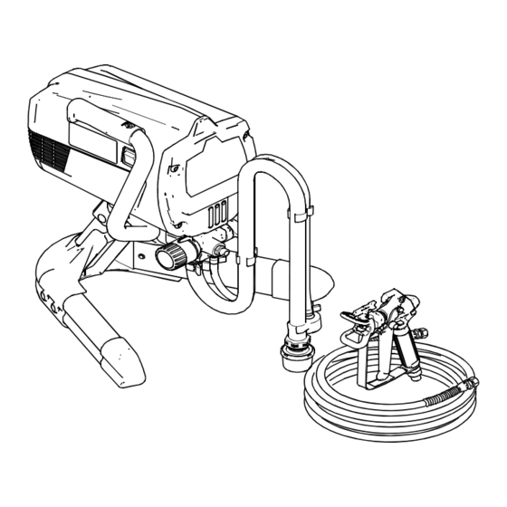
Operation
Tradeworks
Tradeworks
- For portable spray applications of architectural paints and coatings -
(Specifications, page 10.)
IMPORTANT SAFETY INSTRUCTIONS.
Read all warnings and instructions in this
manual and related manuals. Be familiar
with the controls and the proper usage of
the equipment. Save these instructions. See
page 10 for model and series information
including dispense rate, recommended
hose length, guns, and maximum working
pressure.
Tradeworks Project Painter
Model: 826610
™
Project Painter,
™
150 and Tradeworks
™
FIRE AND EXPLOSION HAZARD
•
Use only non-flammable or water-based materi-
als, or non-flammable paint thinners. Do not use
materials having flash points lower than 100°F
(38°C). This includes, but is not limited to, ace-
tone, xylene, toluene, and naphtha. For more
information about your material, request Safety
Data Sheet (SDS) from the supplier.
•
Spraying flammable or combustible materials in
a factory or fixed location must comply with
NFPA 33 and OSHA 1910.94(c) requirements in
the USA and with all similar local regulations in
other countries.
Tradeworks 150
Model: 826620
Visit our website:
http://tradeworkssprayers.com
313381L
170
Tradeworks 170
Model: 826630
ti12937a
EN
Advertisement
Table of Contents


Need help?
Do you have a question about the Tradeworks 150 and is the answer not in the manual?
Questions and answers