Tele Radio T60 Manual
Hide thumbs
Also See for T60:
- Installation instruction (56 pages) ,
- Manual (229 pages) ,
- Manual (29 pages)
Advertisement
Quick Links
Advertisement

Related Manuals for Tele Radio T60


Summary of Contents for Tele Radio T60
- Page 1 Tele Radio Manual Rev. IM-T60-001-A4...
- Page 2 CONTENTS 3-21... Dansk 22-40..Norsk 41-59..Svensk 60-80..Nederlands 81-101.
- Page 3 CONTENTS / AMERICAN Important Information Codes Placement of the Aerial and Receiver The Transmitter The Receiver Supplement for the 460 system Trouble Shooting Chart Service and Support Terms and conditions of sale FCC Statements Coding Tables 1-10,Appendix A Coding Tables 0-15,Appendix B Coding Tables 460-93,Appendix C Connecting the receiver –...
- Page 4 T60 CODES The transmitter and receiver that are to be used together must be coded together before use.The T60 system has two different types of codes. Adjustable codes: All transmitters are equipped with a code switch that consists of 10 three- position switches, which makes it possible to choose freely among 59,049 different codes.
- Page 5 X= 3, 5, or 10m aerial cable DIP-433K3 1/4-433Kx 5/8-433Kx HANDHELD TRANSMITTER MINI T60TX-03SHL T60TX-06SHL T60TX-01SHL with 6 button functions with 3 button functions with 1 button function (A) System switch 1 2 3 5 6 7 8 9 1 0 Battery 3V Code switch...
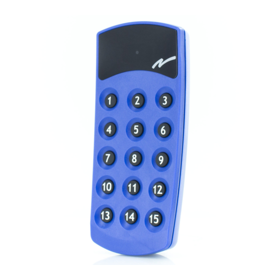
- Page 6 HANDHELD TRANSMITTER MIDI Code switch System switch T60TX-06SOL with 1, 3, 4, or 6 button functions Battery 9V MOBILE TRANSMITTER MAXI Function buttons Port no. buttons Transmitter T60TX-15SML with 15 button functions Shortcuts for functions T60TX-15DML Code switch System switch* Battery 9V *Note: During adjustment, the transmitter must be turned off.
- Page 7 SHORTCUT FOR ONE FUNCTION (T60TX-15DML) The * and # buttons are used to program a shortcut (1 selection per but- ton) for a specific function. To program a shortcut set the port you wish to save, press * or # for more than 3 seconds (the display flashes).The port has now been saved as a shortcut.To reach the shortcut, press the appropriate button once.
- Page 8 4 dual function buttons Stop switch System switch (A1): With (A1) in the ON position, the transmitter communicates with the T60 system and in position 1 (OFF) with the 460 system.When adjusting, the transmitter must be turned off. Mode switch (A2): With (A2) in the ON position, continual transmission is activated (only T60TX-0xERL &...
- Page 9 RECEIVER T60RX-0XYSL Operating voltage: 12-28V AC/DC or 48/115/230V AC Dimensions: 132x133x45mm Enclosure: IP 65 Note: Connecting the recei- ver – see Appendix D 1 2 3 4 5 6 7 8 9 1 0 1 1 1 2 1.Yellow LED. Lights when the receiver has the correct supply voltage.
- Page 10 ROBUST RECEIVER T60RX-0XYSL Operating voltage: 12-28V AC/DC or 48/115/230V AC Dimensions: 175x125x45mm Enclosure: IP 65...
- Page 11 PROGRAMMING RECEIVERS T60RX-0XYSL The function and select buttons on the receiver are used to program it. The function button is used to step through the different program alternatives.The select button is used to confirm program alternative selections. Initially, it is possible to step through the following alternatives by pressing the function button.
- Page 12 5. Program the transmitter’s code by holding down the desired transmitter button until red LED no. 6 flashes three times. Red LED (no. 6) flashes to indicate that the transmitter’s adjustable code has been stored. Adjustable code and fixed individual code 1.
- Page 13 PROGRAMMING THE LATCHING / INSTANTANEOUS FUNCTION The receivers’ relays are set to instantaneous function as standard. 1. Use the function button to select the “latching/instantaneous function” program alternative (YELLOW LED). 2. Confirm the selection with the select button.The red LED above relay 1 lights.
- Page 14 DIN-RECEIVER T60RX-03ADL Frequency: 433.92MHz Operating voltage: 12-24V AC/DC Dimensions: 86x30x58mm Enclosure: IP 20, for internal installation Yellow LED indicates supply Red LED indicates programming voltage. status. Green LED indicates signal reception. Button for self-instruction/ erasing. C NO NC C NO NC C NO NC Power connection.
- Page 15 BNC connector. Red LED indicates programming status. Side Side 2 Yellow LED indicates supply voltage. Green LED indicates signal Button for self-instruction/ reception. erasing. Power connection 11-pin connector 5. 12-24V AC/DC 6. 12-24V AC/DC 10. NO 11. C PROGRAMMING RECEIVER T60RX-03ADL, T60RX-01APL, AND T60RX-01ARL SELF-INSTRUCTION FOR ADJUSTABLE AND FIXED CODES Register adjustable code:...
- Page 16 Register fixed individual code: 1.Press the self-instruction button for at least 0.3 seconds, max. 4 seconds. 2.Release the button (less than 1 second). 3.Press the button again (longer than 1 second). -Private program mode, red LED goes out and lights again. 4.Press the desired function button.
- Page 17 4. Press the desired port number button (0-999) and an optional function button (up, stop, down) on the transmitter. -Red LED flashes three times. 5. Check that the relay switches when one of the transmitter buttons is pressed again. T60TX-0XSHL/T60TX0XSOL AND T60RX-03ADL 1.Check that the transmitter’s system switch (A) is in the ON position.
- Page 18 Press a number followed by the transmit button and verify that the corresponding relay switches. See code table 1-10,Appendix A. * Transmitter T60TX-15DML in the T60 system is compatible with transmitter Type 401RVL9 and 403RVL9 in the 460 system.
- Page 19 Type 460-93 transmitter: 1. Check that the transmitter’s system switch (A) is in position 1 (OFF). 2. Check that code switch (B) 9 is in the + (plus) position. 3. Set codes on the transmitter’s 3 first switches (code switches 1-3) identical to the receiver’s codes (code switches 4-8 not used).
-
Page 20: Service And Support
1. Check that the transmitter’s system switch (A1) is in position 1 (OFF) for the 460 system or in the ON position for the T60 system. 2. Check that the transmitter’s mode switch (A2) is in position 1 (OFF) for normal transmission or in the ON position for continuous transmission. -
Page 21: Troubleshooting Chart
The battery is dis- Replace or charge the does not light when charged. battery. you transmit. The transmitter is Contact Tele Radio’s damaged. support. The range istoo short. Bad battery. Replace the battery. Aerial cables are dam- Check the aerial aged or incorrectly connection. - Page 22 TELERADIO COMPANY TERMS AND CONDITIONS OF SALE 1. AGREEMENT: The Purchaser grants to TeleRadio and TeleRadio retains a security interest in all equipment shipped pursuant to this contract and the proceeds thereof until the Purchaser shall have made full payment for the equipment.
- Page 23 IN NO EVENT WILL TELERADIO BE LIABLE FOR INDIRECT, SPECIAL, INCIDENTAL OR CONSEQUENTIAL DAMAGES.EXCEPT AS STATED ABOVE,TELERADIO MAKES NO REPRESENTATIONS OR WARRANTIES, EXPRESSED OR IMPLIED, NO OTHER REPRESENTATION OR WARRANTY IS GIVEN, AND NO AFFIRMATION OF TELERADIO OR ITS REPRESENTATIVES BY WORD OR ACTION SHALL CONSTITUTE A WARRANTY.
-
Page 24: Fcc Statements
7. RETURNS & CANCELLATIONS: Orders placed by Purchaser, and ente- red upon TeleRadio’s books cannot be canceled or changed except with TeleRadio’s consent and upon terms that will indemnify TeleRadio against all losses. TeleRadio shall not accept returns without a request and authoriza- tion issued by it before shipment. -
Page 25: Coding Tables
APPENDIX A CODING TABLES 1-10 Setting the code on the receiver for operations on the 460 system. Type 401RVL9 and 403RVL9 transmitter with knob 1-10 Table Minus code Table Plus code 1-10 1-10 T5 T6 T7 T8 T5 T6 T7 T8 0(10) 0(10) - Page 26 APPENDIX B CODING TABLES 0-15 Setting the code on the receiver for operations on the 460 system (robust transmitter with control knob). Minus code/Mincode (A) Plus code (B)
- Page 27 APPENDIX C CODING TABLES 460-93 Setting the code on the receiver for operations on the 460 system (460-93 transmitter). Switches 1-3 should have the same setting on both the transmitter and receiver. Note that the positions A0=D0, B0=E0, C0=F0. Code tables ..continued on next page >>>...
- Page 28 APPENDIX C CODING TABLES 460-93 Code tables ..continued on next page >>>...
- Page 29 APPENDIX C CODING TABLES 460-93 Code tables ..continued on next page >>>...
- Page 30 APPENDIX C CODING TABLES 460-93 Code tables ..continued on next page >>>...
- Page 31 APPENDIX C CODING TABLES 460-93...
-
Page 32: Voltage Connections
APPENDIX D VOLTAGE CONNECTIONS T60RX-0xASL 12-30V AC / DC T60RX-0xBSL 230V AC T60RX-0xCSL 48V AC T60RX-0xDSL 115V AC T60RX-04ySL (Standard) C NO NC C NO NC C NO NC C NO NC Supply voltage T60RX-08ySL (Robust) C NO NC C NO NC C NO NC C NO NC C NO NC...
Need help?
Do you have a question about the T60 and is the answer not in the manual?
Questions and answers