Table of Contents
Advertisement
Quick Links
Advertisement
Table of Contents

Related Manuals for Tele Radio Tiger


Summary of Contents for Tele Radio Tiger
- Page 1 Tele Radio Tiger BASIC INSTRUCTIONS FOR 10-BUTTONS TRANSMITTER INSTALL, START, TURN OFF, LOG IN, LOG OUT, REGISTER, ERASE, TROUBLE SHOOTING. EXCEPTIONAL SITUATIONS ENGLISH (ORIGINAL) ARTICLE CODE: RX1-A, RX2-A, RX3-A, TX1-A, TG-R1-1-0000, TG-R1-11-0000, TG-R1-6-0000, TG-T3-4-0000 IM-TG-TX010-A04-EN...
- Page 2 The information shall not be handed to end users. The instructions may be removed or revised by Tele radio AB at any time and without any further notice. Corrections and additions will be added to the updated versions of the instructions.
-
Page 3: Table Of Contents
CONTENTS SIL INFORMATION TECHNICAL DATA RECEIVER CURRENT CONSUMPTION INSTALL THE RECEIVER INSTALL THE ANTENNA THE RECEIVER MENU THE TRANSMITTER THE TRANSMITTER MENU HOW TO NAVIGATE IN THE TRANSMITTER MENU START UP IN TRANSMITTER MENU MODE START THE TRANSMITTER IN OPERATING MODE TURN THE TRANSMITTER OFF REGISTER THE TRANSMITTER IN THE RECEIVER LOG THE TRANSMITTER IN... -
Page 4: Sil Information
SIL INFORMATION SYSTEM REQUIREMENTS The product holds two safety-related functions that comply with the requirements for SIL3 according to IEC61508: • Stop function: Deactivates all relays on the receiver when the STOP button on the transmitter is pressed. • Safe function: Activates the safe function relays on the receiver when both safe buttons on the transmitter are pressed. - Page 5 Receiver Stop function: λ Probability of dangerous failure per hour PFHd = 30.1 FITs(= Fraction of total failure rate with dangerous λ and detected consequence = 685.0 FITs Diagnostic coverage DC = 96.9% Safe failure fraction SFF = 98.7 % Common cause failure 8.0 FIT Level of hardware fault tolerance...
- Page 6 WARNING: RECEIVERS RX-1A, RX-2A, RX-3A SYSTEM SETUP> >Register TX Danger! High Voltage Danger! High Voltage ! Hi h V l l 15 16 17 18 19 20 21 22 23 24 25 26 27 28 29 30 31 32 33 34 35 36 37 38 39 40 41 42 43 44 45 46 47 48 49 50 51 52 53 54 55 56 57 58 59 60 sF1 sF2 DO NOT TOUCH THE AREA MARKED WITH GREY!
- Page 7 RX-1A RECEIVER (BASE BOARD) SYSTEM SETUP> >Register TX Danger! High Voltage 15 16 17 18 19 20 21 22 23 24 25 26 27 28 29 30 31 32 33 34 35 36 37 38 39 40 41 42 43 44 45 46 47 48 49 50 51 52 53 54 55 56 57 58 59 60 sF1 sF2 RX2-A RECEIVER (BASE BOARD WITH RELAY EXPANSION BOARD)
- Page 8 RX-3A RECEIVER (BASE BOARD WITH FIELDBUS EXPANSION BOARD) SYSTEM SETUP> >Register TX Danger! High Voltage 15 16 17 18 19 20 21 22 23 24 25 26 27 28 29 30 31 32 33 34 35 36 37 38 39 40 41 42 43 44 45 46 47 48 49 50 51 52 53 54 55 56 57 58 59 60 sF1 sF2 1.
- Page 9 STOP RELAYS The STOP button controls the 2 stop relays. When the STOP button is pressed, the STOP relays deactivates immediately. NOTE! If the stop commands for some reason are being blocked, the STOP relays will deactivate after 0.5 seconds or less. SAFE FUNCTION RELAYS The safe buttons activate the 2 safe function relays when pressed to the second step.
- Page 10 ANTENNA CONNECTORS The receiver comes with 2 antenna connectors. If using only one antenna, connect to any one of the antenna connectors. If using 2 antennas, one of them should be connected via a coaxial cable (at least 1 metre) to avoid radio disturbances.
-
Page 11: Technical Data Receiver
TECHNICAL DATA RECEIVER RX-1A, RX-2A, RX-3A RELAY OUTPUTS: 2 Stop relays. Potential free*, makes/breaks 16A AC1. 2 Safe functions relays. Potential free*, makes/breaks 16A AC1. 12/ 28 functions relays. Potential free*, makes/breaks 16A AC1. OPERATING FREQUENCY: 433.075-434.775 MHz. CHANNELS: SIZE: 250 x 175 x 75 mm. -
Page 12: Install The Receiver
When installing the antenna on a wall, use a wall bracket. IMPORTANT! Tele Radio remote controls are often built into wider applications. We recommend that the system is provided with a wired emergency stop where necessary. -
Page 13: The Receiver Menu
THE RECEIVER MENU SETTINGS> >Register TX >Show TX >Logout TX >Relay control RECEIVER BASE SOFTWARE All of the base software settings are described in this installation instruction. The SYSTEM SETUP submenues are: • Register TX • Show TX • Logout TX •... -
Page 14: The Transmitter
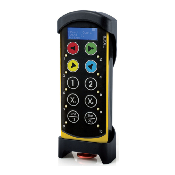
THE TRANSMITTER >SETTINGS 1.Rubber cover 7. Button 7-Safe button 13. Button 10-Start button 2. Top LED 8. Button 9-Start button 14. LEDs 1-10 3.Display 9. Button 2 15. STOP button 4.Button 1 10.Button 4 5.Button 3 11.Button 6 6.Button 5 12.Button 8-Safe button TECHNICAL DATA DEGREE OF PROTECTION:... -
Page 15: The Transmitter Menu
THE TRANSMITTER MENU SETTINGS 1: 433.075MHz... >Channel 69: 434.775MHz... E.g. 1: 92041 >Show receivers E.g. 2: 90088... E.g. 1: 92041 >Logout E.g. 2: 90088... >Register E.g. 1: 92041 >Erase E.g. 2: 90088... >Replace >Show SW version >Test Mode HOW TO NAVIGATE IN THE TRANSMITTER MENU •... -
Page 16: Start Up In Transmitter Menu Mode
START UP IN TRANSMITTER MENU MODE Pull out the STOP button. Enter your PIN code if you have one. If you need to enter a PIN code to start, you will get a warning message in the display. Press button 10. Keep pressed. Press the STOP button. -
Page 17: Register The Transmitter In The Receiver
REGISTER THE TRANSMITTER IN THE RECEIVER • 1-15 transmitters can be registered in each receiver • 1-15 receivers can be registered in each transmitter • 1-8 receivers can be operated during the session (a session is defined as the time between starting and stopping of a transmitter). -
Page 18: Erase A Registered Transmitter
ERASE A REGISTERED TRANSMITTER IMPORTANT! The recommended way to erase a transmitter from the receiver, is to do it from the transmitter menu. This way the transmitter is erased from the receiver and the receiver is erased from the transmitter. Start up the transmitter in menu mode. -
Page 19: Replace A Transmitter
REPLACE A TRANSMITTER You can replace a transmitter with a new transmitter without having physical access to the receiver, e.g. when the transmitter is lost or broken, and you need to switch to a new transmitter. If the transmitter that you want to replace is logged on, the new transmitter will be logged on instead after replacement. -
Page 20: Change Automatic Shutdown Time
CHANGE AUTOMATIC SHUTDOWN TIME The factory default setting for automatic shutdown is 6 minutes. Start up the transmitter in menu mode. See ”Start up the transmitter in menu mode”. Select [Auto shutdown]. Scroll to: • 6 min • 2 min • Off • 12 min Select by pressing button 9. The automatic shutdown time is now changed.
Need help?
Do you have a question about the Tiger and is the answer not in the manual?
Questions and answers