
Related Manuals for Tele Radio T29-12


Summary of Contents for Tele Radio T29-12
- Page 1 USER INSTRUCTIONS Transmitter: T29-12 T 2 9 ED-PN-TX108-EN-v04 Language: English (original)
- Page 2 ©Tele-Radio i Lysekil AB August Barks gata 30A SE-421 32 Västra Frölunda Sweden Phone: +46 (0)31 748 54 60...
- Page 3 CHAPTER 1: INTRODUCTION 1.1 About this document 1.2 About T29 transmitters CHAPTER 2: SAFETY 2.1 Warnings & restrictions 2.2 Safety features CHAPTER 3: FUNCTIONAL SAFETY 3.1 Safety function 3.2 Applicable products 3.3 Installation 3.4 Configuration 3.5 Interface CHAPTER 4: TECHNICAL DATA 4.1 Transmitter specifications 4.2 Radio frequency band CHAPTER 5: PRODUCT GENERAL DESCRIPTION 5.1 Transmitter front 5.2 Transmitter back CHAPTER 6: STATUS AND ERROR INDICATIONS...
- Page 4 10.2 United Kingdom 10.3 North America 10.4 Brazil ANNEX A: INDEX...
-
Page 5: Chapter 1: Introduction
READ ALL INSTRUCTIONS AND WARNINGS CAREFULLY BEFORE OPERATING THE PRODUCTS. These User instructions have been published by Tele Radio and are not subject to any guarantees. The User instructions may be withdrawn or revised by Tele Radio at any time and without further notice. Corrections and updates will be added to the latest version of the manual. - Page 6 1 . 1 A b o u t t h i s d o c u m e n t Before installing or operating the product, read the corresponding documentation carefully. Tele Radio's product range is composed of transmitters, receivers, and accessories intended for use together as a system. These User instructions cover general safety issues, main technical specifications, standard operating instructions and battery information.
- Page 7 1 . 2 . 1 O V E R V I E W O F T H E A V A I L A B L E M O D E L Frequency Model Number of 2-step buttons Display 2.4 Ghz T29-12 – ● – Not available ● Standard ED-PN-TX108-EN-v04...
- Page 8 The following information is intended for use as a complement to applicable local regulations and standards. IMPORTANT! Tele Radio remote controls are often built into wider applications. These systems should be equipped with: • a wired emergency stop where necessary •...
- Page 9 User instructions│ T29│ Chapter 2: Safety Always follow operating and maintenance instructions as well as all applicable safety procedures and requirements. Do not open the receiver encapsulation unless you are qualified. You must satisfy the age requirements in your country for operating the equipment.
- Page 10 2 . 2 S a f e t y f e a t u r e s 2 . 2 . 1 S T O P B U T T O N Tele Radio transmitters are equipped with a stop button. When the Stop button is pressed, the stop relays on the receiver deactivate.
-
Page 11: Chapter 3: Functional Safety
User instructions│ T29│ Chapter 3: Functional safety CHAPTER 3: FUNCTIONAL SAFETY NOTE: The information in this section applies only to the products specified below. 3 . 1 S a f e t y f u n c t i o n The safety-related stop function in the radio system complies with EN 13849-1:2015 PLd category 3. - Page 12 User instructions│ T29│ Chapter 3: Functional safety Function LED Status Indicates PLd status LED (red) Not compliant with PLd Compliant with PLd R15-01, R15-02, R15-07, R15-08 R15-13, R15-14 1. Stop relays SR1–2 2. PLd status LED (red) IMPORTANT! All safety-related parameters must be configured as follows in order to comply with the appointed safety requirements: The system must be configured in continuous radio mode.
- Page 13 User instructions│ T29│ Chapter 3: Functional safety details. The parameter ' ' must be START bit in Gen2 packet for session activated. See "3.4.1 'START status'/'START bit' parameters" for more details. 3 . 4 . 1 ' S T A R T S T A T U S ' / ' S T A R T B I T ' P A R A M E T E R S When the transmitter is started it will send start commands for 200 ms.
-
Page 14: Chapter 4: Technical Data
CHAPTER 4: TECHNICAL DATA 4 . 1 T r a n s m i t t e r s p e c i f i c a t i o n s T29-12 Number of buttons 12 x 2-step buttons I/O switch... - Page 15 User instructions│ T29│ Chapter 4: Technical data 4 . 2 R a d i o f r e q u e n c y b a n d For radio systems operating on frequency band 2.4 GHz, the frequency band is divided into 16 channels (11 to 26).
-
Page 16: Chapter 5: Product General Description
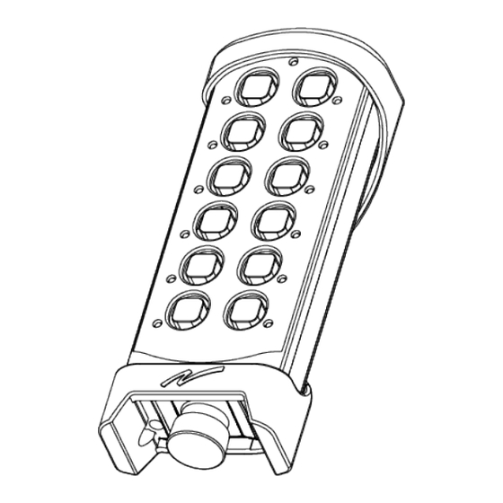
CHAPTER 5: PRODUCT GENERAL DESCRIPTION The pictures shown in this chapter are for illustrative purposes only. 5 . 1 T r a n s m i t t e r f r o n t T29-12 1. Rubber cover 7. Button 5 12. - Page 17 LED) for battery indication and radio link information. For more details, see "Chapter 6: Status and error indications" 5 . 2 T r a n s m i t t e r b a c k T29-12 1. Rubber cover 4. Product label 6. Battery compartment 2.
- Page 18 User instructions│ T29│ Chapter 6: Status and error indications CHAPTER 6: STATUS AND ERROR INDICATIONS 6 . 1 T o p L E D s t a t u s i n d i c a t i o n The top LED flashes green when the battery capacity is good and red when the battery capacity is poor.
- Page 19 User instructions│ T29│ Chapter 6: Status and error indications 6 . 2 . 1 T E S T T H E S T O P B U T T O N NOTE: A test of the stop button is required in both "pulled out" and "pressed in" positions.
- Page 20 User instructions│ T29│ Chapter 6: Status and error indications 6 . 3 E r r o r i n d i c a t i o n s a n d c o d e m e s s a g e s Each error is identified by a code indicated by a LED combination including the top LED (LED 0) and button LEDs 1–5.
- Page 21 User instructions│ T29│ Chapter 6: Status and error indications LED0 LED1 LED2 LED3 LED4 LED5 Error code Indicates green/red FATAL_ERROR_ 'Wrong Stop button status during ž ˜ ™ ˜ ™ ™ PNG2_MODULE_ memory test' INCONSISTENCY (during memory test, the stop button status saved in memory is different from the one created when building the radio package).
- Page 22 User instructions│ T29│ Chapter 6: Status and error indications LED0 LED1 LED2 LED3 LED4 LED5 Error code Indicates green/red FATAL_ERROR_ 'Stop button is returning a incorrect ž ™ ™ ˜ ˜ ™ STOP_BUTTON_ value' CPU1_ADC_ Test the stop button (see "6.2.1 ...
-
Page 23: Chapter 7: Operation
User instructions│ T29│ Chapter 7: Operation CHAPTER 7: OPERATION 7 . 1 G e n e r a l i n f o r m a t i o n To control a receiver, the transmitter must be registered and logged in to the receiver. - Page 24 7 . 3 F u n c t i o n a l i t y t e s t NOTE: This list is intended for use as a support for the manufacturer of the equipment where Tele Radio remote control systems are installed. Before operating the radio system, follow the procedure below.
- Page 25 User instructions│ T29│ Chapter 7: Operation 7 . 4 S t a r t a s e s s i o n To be able to control a receiver with the transmitter, the transmitter must be registered in the receiver. When starting the transmitter, it will automatically log in to the receiver(s) it has been registered in, provided that no other transmitter is already logged in to the receiver(s).
- Page 26 User instructions│ T29│ Chapter 7: Operation 7 . 5 L o g t h e t r a n s m i t t e r o u t f r o m a r e c e i v e r IMPORTANT! For the logout function to work, BOTH the receiver and the transmitter must have the logout function activated and be set to continuous radio mode.
-
Page 27: Chapter 8: Battery
User instructions│ T29│ Chapter 8: Battery CHAPTER 8: BATTERY 8 . 1 B a t t e r y p r e c a u t i o n s Carefully read the following safety instructions and warnings before using, charging or disposing of the batteries. - Page 28 User instructions│ T29│ Chapter 8: Battery 8 . 1 . 2 D I S P O S A L When discarding batteries, insulate the + and - terminals of batteries with insulating/ masking tape. Do not place multiple batteries in the same plastic bag. Do not incinerate or dispose of batteries in fire.
- Page 29 8 . 2 B a t t e r y i n f o r m a t i o n NOTE: Only batteries approved by Tele Radio should be used in T29 transmitters. NOTE: When the battery capacity reaches approximately 10 %, the top LED lights red.
- Page 30 User instructions│ T29│ Chapter 8: Battery 8 . 2 . 1 C H A R G E T H E B A T T E R Y Battery D4-02 can be charged directly on the transmitter with an AC adapter, or in the table charger D4-01/M769755.
- Page 31 User instructions│ T29│ Chapter 8: Battery C h a r g i n g u s i n g t h e c h a r g e r u n i t 1. Remove the rubber cover from the transmitter.
-
Page 32: Maintenance
Tele Radio products are covered by a warranty against material, construction and manufacturing faults. During the warranty period, Tele Radio may replace the product or faulty parts. Work under warranty must be performed by Tele Radio or by an authorized service center specified by Tele Radio. -
Page 33: Chapter 10: Regulatory Information
For proper treatment, recovery and recycling, please take this product to a designated collection point. Tele Radio strives to minimize the use of hazardous materials, promotes reuse and recycling, and reduces emissions to air, soil and water. When a commercially viable alternative is available, Tele Radio strives to restrict or eliminate substances and materials that pose an environmental, health or safety risk. - Page 34 1 0 . 3 N o r t h A m e r i c a Applies to: T29, T29-12 1 0 . 3 . 1 F C C S T A T E M E N T This device complies with part 15 of the FCC Rules.
- Page 35 User instructions│ T29│ Chapter 10: Regulatory information 1 0 . 3 . 2 I C S T A T E M E N T This product complies with Industry Canada's licence-exempt RSSs. Operation is subject to the following two conditions: (1) This device may not cause interference; and (2) This device must accept any interference, including interference that may cause undesired operation of device.
- Page 36 1 0 . 4 B r a z i l Applies to: T29, T29-12 1 0 . 4 . 1 A N A T E L S T A T E M E N T ( D E C L A R A Ç Ã O A N A T E L ) Este equipamento não tem direito à...
- Page 37 User instructions│ T29│ Annex A: Index ANNEX A: INDEX ANATEL Statement Battery Battery information Charge Battery precautions Handling Storage CE marking Charging temperature 14, 29 Dimensions Disposal FCC statement FCC/IC labels Functionality test IC Statement IP code Log out Quick logout ED-PN-TX108-EN-v04...
- Page 38 User instructions│ T29│ Annex A: Index M245060 Maintenance Number of channels Operating temperature Operating time Power supply Radio frequency band 2.4 GHz Frequency channels Radio frequency output power Radio mode Safety Features Safety levels Start a session Start the transmitter Stop button Storage temperature Battery...
- Page 39 User instructions│ T29│ Annex A: Index Transmitter front views Warnings & restrictions Maintenance Operation WEEE directive Weight ED-PN-TX108-EN-v04...
- Page 40 These user instructions are subject to change without prior notice. Download the latest instructions from www.tele-radio.com.
Need help?
Do you have a question about the T29-12 and is the answer not in the manual?
Questions and answers