
Related Manuals for Tele Radio T29-12


Summary of Contents for Tele Radio T29-12
- Page 1 INSTALLATION INSTRUCTIONS Transmitters: T29-12 safe smart strong T 2 9 IM-PN-TX108-CERT-v01pre8 Language: English (original)
- Page 2 ©Tele Radio AB Datavägen 21 SE-436 32 Askim Sweden Phone: +46 (0)31 748 54 60...
-
Page 3: Table Of Contents
CHAPTER 1: INTRODUCTION 1.1 About this document 1.2 About T29 transmitters CHAPTER 2: SAFETY 2.1 Warnings & restrictions 2.2 Safety features CHAPTER 3: FUNCTIONAL SAFETY 3.1 Safety function 3.2 Applicable products 3.3 Installation 3.4 Configuration 3.5 Interface CHAPTER 4: TECHNICAL DATA 4.1 Transmitter specifications 4.2 Radio frequency band CHAPTER 5: PRODUCT GENERAL DESCRIPTION 5.1 Transmitter front 5.2 Transmitter back 5.3 Top LED... - Page 4 8.5 Show current radio frequency channel 8.6 Set the radio inactivity timeout (automatic shutdown) 8.7 Load select mode 8.8 Logout from Menu mode 8.9 Select a radio frequency channel 8.10 Load at start-up CHAPTER 9: BATTERY 9.1 Battery precautions 9.2 Battery information CHAPTER 10: WARRANTY, SERVICE, REPAIRS, AND MAINTENANCE CHAPTER 11: REGULATORY INFORMATION 11.1 Europe 11.2 North America...
-
Page 5: Chapter 1: Introduction
These Installation instructions have been published by Tele Radio AB and are not subject to any guarantees. The Installation instructions may be withdrawn or revised by Tele Radio AB at any time and without further notice. Corrections and updates will be added to the latest version of the manual. Always download the Installation instructions from our website, www.tele-radio.com, for the latest... - Page 6 For battery precautions, see "9.1 Battery precautions". Tele Radio AB products are covered by a warranty against material, construction, or manufacturing faults. See "Chapter 10: Warranty, service, repairs, and maintenance". IM-PN-TX108-CERT-v01pre8...
-
Page 7: About This Document
1 . 1 A b o u t t h i s d o c u m e n t Before installing or operating the product, read the corresponding documentation carefully. Tele Radio AB's product range is composed of transmitters, receivers, and accessories intended for use together as a system. These Installation instructions cover general safety issues, main technical specifications, standard installation, configuration and operating instructions, general troubleshooting and battery information. -
Page 8: About T29 Transmitters
1 . 2 . 1 O V E R V I E W O F T H E A V A I L A B L E M O D E L Step buttons transmitters Frequency Number of buttons Model Display 2.4 Ghz ● ● T29-12 – ● Standard – Not available IM-PN-TX108-CERT-v01pre8... -
Page 9: Chapter 2: Safety
IMPORTANT! Tele Radio AB remote controls are often built into wider applications. These systems should be equipped with: • a wired emergency stop where necessary •... - Page 10 Installation instructions│ T29│ Chapter 2: Safety 2 . 1 . 2 O P E R A T I O N Only qualified personnel should be permitted to access the transmitter and operate the equipment. This equipment is not suitable for use in locations where children are likely to be present.
-
Page 11: Safety Features
2 . 2 S a f e t y f e a t u r e s 2 . 2 . 1 S T O P B U T T O N Tele Radio AB transmitters are equipped with a stop button. -
Page 12: Chapter 3: Functional Safety
Installation instructions│ T29│ Chapter 3: Functional safety CHAPTER 3: FUNCTIONAL SAFETY NOTE: The information in this section applies only to the products specified below. 3 . 1 S a f e t y f u n c t i o n The safety-related stop function in the radio system complies with EN 13849-1:2015 PLd category 3. - Page 13 Installation instructions│ T29│ Chapter 3: Functional safety Function LED Status Indicates PLd status LED (red) Not compliant with PLd Compliant with PLd R15-01, R15-02, R15-07, R15-08 R15-13, R15-14 1. Stop relays SR1–2 2. PLd status LED (red) IMPORTANT! All safety-related parameters must be configured as follows in order to comply with the appointed safety requirements: The system must be configured in continuous radio mode.
-
Page 14: Interface
Installation instructions│ T29│ Chapter 3: Functional safety details. The parameter ' ' must be START bit in Gen2 packet for session activated. See "3.4.1 'START status'/'START bit' parameters" for more details. 3 . 4 . 1 ' S T A R T S T A T U S ' / ' S T A R T B I T ' P A R A M E T E R S When the transmitter is started it will send start commands for 200 ms. -
Page 15: Chapter 4: Technical Data
CHAPTER 4: TECHNICAL DATA 4 . 1 T r a n s m i t t e r s p e c i f i c a t i o n s T29-12 Number of buttons 12 x 2-step buttons I/O switch... - Page 16 Installation instructions│ T29│ Chapter 4: Technical data Channel Frequency (MHz) Channel Frequency (MHz) 2415 2455 2420 2460 2425 2465 2430 2470 2435 2475 2440 2480 IM-PN-TX108-CERT-v01pre8...
-
Page 17: Chapter 5: Product General Description
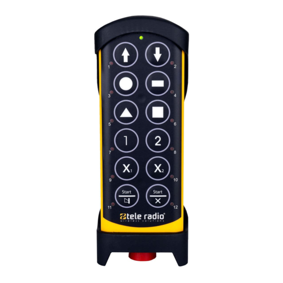
CHAPTER 5: PRODUCT GENERAL DESCRIPTION The pictures shown in this chapter are for illustrative purposes only. 5 . 1 T r a n s m i t t e r f r o n t T29-12 1. Rubber 7. Button 5 10. -
Page 18: Transmitter Back
Installation instructions│ T29│ Chapter 5: Product general description 5 . 2 T r a n s m i t t e r b a c k T29-12 1. Rubber cover 4. Product label 6. Battery compartment 2. Clip 5. -
Page 19: Chapter 6: Status And Error Indications
Installation instructions│ T29│ Chapter 6: Status and error indications CHAPTER 6: STATUS AND ERROR INDICATIONS 6 . 1 T o p L E D s t a t u s i n d i c a t i o n The top LED lights or flashes green when the battery capacity is good and red when the battery capacity is poor. -
Page 20: Error Indications And Code Messages
Installation instructions│ T29│ Chapter 6: Status and error indications 6 . 3 E r r o r i n d i c a t i o n s a n d c o d e m e s s a g e s Each error is identified by a code indicated by a LED combination including the top LED (LED 0) and button LEDs 1–5. - Page 21 Installation instructions│ T29│ Chapter 6: Status and error indications LED0 LED1 LED2 LED3 LED4 LED5 Error code Indicates green/red FATAL_ERROR_ 'Radio initialization has ž ™ ˜ ™ ™ ™ FAILED_RADIO_ failed' INIT For this error code, contact technical support FATAL_ERROR_ 'Stop button failure' ž...
- Page 22 Installation instructions│ T29│ Chapter 6: Status and error indications LED0 LED1 LED2 LED3 LED4 LED5 Error code Indicates green/red FATAL_ERROR_ 'No answer from CPU2' ž ˜ ˜ ˜ ™ ™ CPU2_PROBING For this error code, contact technical support FATAL_ERROR_ 'Incompatible SW ž...
- Page 23 Installation instructions│ T29│ Chapter 6: Status and error indications LED0 LED1 LED2 LED3 LED4 LED5 Error code Indicates green/red FATAL_ERROR_ 'Stop button is ž ™ ™ ˜ ˜ ™ STOP_BUTTON_ returning a incorrect CPU1_ADC_ value' VALUE_INVALID Test the stop button (see "6.3.1 ...
- Page 24 Installation instructions│ T29│ Chapter 6: Status and error indications 6 . 3 . 1 T E S T T H E S T O P B U T T O N A test of the Stop button must be performed if one of the following errors occur when pulling out the stop button to start the transmitter: FATAL_ERROR_STOP_BUTTON_FAILED (top LED is flashing red/green, LEDs 1+2 are lit, all other LEDs are off)
-
Page 25: Chapter 7: Operation
Installation instructions│ T29│ Chapter 7: Operation CHAPTER 7: OPERATION 7 . 1 G e n e r a l i n f o r m a t i o n To control a receiver, the transmitter must be registered and logged in to the receiver. -
Page 26: Functionality Test
7 . 3 F u n c t i o n a l i t y t e s t NOTE: This list is intended for use as a support for the manufacturer of the equipment where Tele Radio AB remote control systems are installed. Before operating the radio system, follow the procedure below. -
Page 27: Start A Session
Installation instructions│ T29│ Chapter 7: Operation 7 . 4 S t a r t a s e s s i o n To be able to control a receiver with the transmitter, the transmitter must be registered in the receiver. When starting the transmitter, it will automatically log in to the receiver(s) it has been registered in, provided that no other transmitter is already logged in to the receiver(s). -
Page 28: Log The Transmitter Out From A Receiver
Installation instructions│ T29│ Chapter 7: Operation 7 . 5 L o g t h e t r a n s m i t t e r o u t f r o m a r e c e i v e r IMPORTANT! For the logout function to work, BOTH the receiver and the transmitter must have the logout function activated and be set to continuous radio mode. -
Page 29: Chapter 8: Configuration Menu
Installation instructions│ T29│ Chapter 8: Configuration menu CHAPTER 8: CONFIGURATION MENU 8 . 1 R e g i s t e r t h e t r a n s m i t t e r i n a r e c e i v e r 8 . - Page 30 Installation instructions│ T29│ Chapter 8: Configuration menu NOTE: To establish a radio link between the transmitter and the receiver, both units must be set to the same radio mode. 1. Make sure that the Stop button is pressed. 2. Twist and release the Stop button. The top LED lights (green when the battery capacity is good, red when the battery capacity is poor).
-
Page 31: Menu Mode And Standard Settings
Select a load option (0–8) Logout Log out the transmitter from a receiver 6 + 2 Switch channel Select the channel to use 6 + 4 Load at start-up Select the default load at start up T29-12: button 12. IM-PN-TX108-CERT-v01pre8... -
Page 32: Enter Menu Mode
If the code is invalid, the transmitter turns off. Go back to step 1 and try again. WITHIN 1 MINUTE OF ENTERING THE CODE: 6. Select a menu by pressing a button according to the following table. Menu T29-12 Replace Button 3 Show channel Button 4... -
Page 33: Replace A Transmitter
Installation instructions│ T29│ Chapter 8: Configuration menu 8 . 4 R e p l a c e a t r a n s m i t t e r It is possible to replace a registered transmitter with another transmitter of the same model. - Page 34 Installation instructions│ T29│ Chapter 8: Configuration menu 1. Make sure that the Stop button is pressed. 2. Press and hold button 12. 3. Twist and release the Stop button. 4. Release button 12. The top LED flashes (green). WITHIN 1 MINUTE OF RELEASING THE STOP BUTTON: 5.
-
Page 35: Show Current Radio Frequency Channel
Installation instructions│ T29│ Chapter 8: Configuration menu 8 . 5 S h o w c u r r e n t r a d i o f r e q u e n c y c h a n n e l 1. -
Page 36: Set The Radio Inactivity Timeout (Automatic Shutdown)
6. Press button 5 to enter the [Automatic shutdown] menu. The top LED lights (green). LED 2 flashes (red). 7. Select the automatic shutdown time by pressing a button according to the following table. Automatic shutdown time T29-12 3 minutes Button 1 6 minutes Button 2... -
Page 37: Load Select Mode
6. Press button 6 to enter the [Load select mode] menu. The top LED lights (green). LED 2 flashes (red). 7. Select a Load select mode by pressing a button according to the following table. Load select Default load selected T29-12 mode at start-up 0 (default) none Button 11... - Page 38 Installation instructions│ T29│ Chapter 8: Configuration menu 8 . 7 . 1 L O A D S E L E C T M O D E 0 – 8 Load select mode 0 Load select mode 1 Load select mode 2 Load select mode 3 IM-PN-TX108-CERT-v01pre8...
- Page 39 Installation instructions│ T29│ Chapter 8: Configuration menu Load select mode 4 Load select mode 5 Load select mode 6 Load select mode 7 IM-PN-TX108-CERT-v01pre8...
- Page 40 Installation instructions│ T29│ Chapter 8: Configuration menu Load select mode 8 IM-PN-TX108-CERT-v01pre8...
-
Page 41: Logout From Menu Mode
Installation instructions│ T29│ Chapter 8: Configuration menu 8 . 8 L o g o u t f r o m M e n u m o d e This logout option is mainly used when the button for quick logout is used by another function. -
Page 42: Select A Radio Frequency Channel
The top LED lights (green). LED 2 flashes (red). The transmitter enters the [Switch channel] menu. 10. Enter the first digit of the new channel (11–26) by pressing the buttons according to the following table. Digit T29-12 Other alternatives 1–6 Buttons 1–6 Button 7... - Page 43 Installation instructions│ T29│ Chapter 8: Configuration menu 11. Enter the second digit. LED 4 lights (red) when a valid digits has been entered. The top LED flashes (green) 3 times. The transmitter turns off. To check that the channel has been properly changed, see "8.5 ...
-
Page 44: Load At Start-Up
The top LED lights (green). LED 2 flashes (red). The transmitter enters the [Load at start-up] menu. 10. Select the load at start-up by pressing a button according to the following table. Load at start-up T29-12 Button 1 Button 2 Button 3 none Button 11 The top LED flashes (green) 3 times. -
Page 45: Chapter 9: Battery
Installation instructions│ T29│ Chapter 9: Battery CHAPTER 9: BATTERY 9 . 1 B a t t e r y p r e c a u t i o n s Carefully read the following safety instructions and warnings before using, charging or disposing of the batteries. - Page 46 Installation instructions│ T29│ Chapter 9: Battery 9 . 1 . 2 D I S P O S A L When discarding batteries, insulate the + and - terminals of batteries with insulating/ masking tape. Do not place multiple batteries in the same plastic bag. Do not incinerate or dispose of batteries in fire.
-
Page 47: Battery Information
Installation instructions│ T29│ Chapter 9: Battery 9 . 2 B a t t e r y i n f o r m a t i o n NOTE: Only batteries approved by Tele Radio AB should be used in T29 transmitters. - Page 48 Installation instructions│ T29│ Chapter 9: Battery 9 . 2 . 1 C H A R G E T H E B A T T E R Y 1. When the battery capacity reaches approximately 10 %, the top LED lights red. 2.
- Page 49 Installation instructions│ T29│ Chapter 9: Battery 3. The top LED turns green when the battery is fully charged,. Charger unit: The charger's LED turns green when the battery is fully charged. 4. Remove the charger plug and close the protection cap. For external batteries, remove the battery from the charger unit and put it back in the transmitter.
-
Page 50: Chapter 10: Warranty, Service, Repairs, And Maintenance
Tele Radio AB products are covered by a warranty against material, construction and manufacturing faults. During the warranty period, Tele Radio AB may replace the product or faulty parts. Work under warranty must be performed by Tele Radio AB or by an authorized service center specified by Tele Radio AB. -
Page 51: Chapter 11: Regulatory Information
For proper treatment, recovery and recycling, please take this product to a designated collection point. Tele Radio AB strives to minimize the use of hazardous materials, promotes reuse and recycling, and reduces emissions to air, soil and water. When a commercially viable alternative is available, Tele Radio AB strives to restrict or eliminate substances and materials that pose an environmental, health or safety risk. - Page 52 Installation instructions│ T29│ Chapter 11: Regulatory information (2) this device must accept any interference received, including interference that may cause undesired operation. Changes or modifications not expressly approved by the party responsible for compliance could void the user’s authority to operate the equipment. This equipment has been tested and found to comply with the limits for a Class B digital device, pursuant to part 15 of the FCC Rules.
-
Page 53: Annex 12: Glossary
Installation instructions│ T29│ Annex 12: Glossary ANNEX 12: GLOSSARY Diagnostic Coverage Failures in time (1 FIT = 1 failure per 10^9 hours) Hardware Fault Tolerance MTTF Mean Time To Failure Probability of Failure per Hour Performance level Safety Failure Fraction Safety Integrity Level IM-PN-TX108-CERT-v01pre8... -
Page 54: Annex 13: Index
Installation instructions│ T29│ Annex 13: Index ANNEX 13: INDEX Automatic shutdown Battery Battery information Charge Battery precautions Handling Storage CE marking Charging temperature 15, 47 Configuration menu Dimensions Disposal FCC statement Functionality test IC Statement Inactivity timeout IP code Load at start-up Load select mode IM-PN-TX108-CERT-v01pre8... - Page 55 Installation instructions│ T29│ Annex 13: Index Log out Logout from Menu mode Quick logout M245060 Maintenance Menu mode Enter Menu mode, no PIN code Number of channels Operating temperature Operating time Power supply Radio frequency band 2.4 GHz Frequency channels Radio frequency output power Radio mode Register...
- Page 56 Installation instructions│ T29│ Annex 13: Index Show current radio frequency channel Start a session Start the transmitter Stop button Storage temperature Battery Top LED 18-19 Transmitter back Transmitter front views Warnings & restrictions Installation and commission Maintenance Operation WEEE directive Weight IM-PN-TX108-CERT-v01pre8...
- Page 57 Installation instructions│ T29│ This page intentionally left blank. IM-PN-TX108-CERT-v01pre8...
- Page 58 safe smart strong These Installation instructions are subject to change without prior notice. Download the latest Installation instructions from www.tele-radio.com .