
Related Manuals for Tele Radio T19-02


Summary of Contents for Tele Radio T19-02
- Page 1 INSTALLATION INSTRUCTIONS Transmitter: T19-02 safe smart strong T 1 9 IM-PN-TX103-EN-v07 Language: English (original)
- Page 2 ©Tele Radio AB Datavägen 21 SE-436 32 Askim Sweden Phone: +46 (0)31 748 54 60...
-
Page 3: Table Of Contents
Installation instructions│ T19│ CHAPTER 1: INTRODUCTION 1.1 About this document 1.2 About T19 transmitters CHAPTER 2: SAFETY 2.1 Warnings & restrictions 2.2 Safety features CHAPTER 3: FUNCTIONAL SAFETY 3.1 Safety function 3.2 Applicable products 3.3 Installation 3.4 Configuration 3.5 Interface CHAPTER 4: TECHNICAL DATA 4.1 Transmitter specifications 4.2 Radio frequency band CHAPTER 5: PRODUCT GENERAL DESCRIPTION 5.1 Transmitter front 5.2 Transmitter back... - Page 4 Installation instructions│ T19│ 8.7 Set the radio inactivity timeout (automatic shutdown) 8.8 Load select mode 8.9 Logout from Menu mode 8.10 Select a radio frequency channel 8.11 Load at start-up CHAPTER 9: BATTERY 9.1 Battery precautions 9.2 Battery information CHAPTER 10: FOILS 10.1 Affix a foil to the transmitter CHAPTER 11: WARRANTY, SERVICE, REPAIRS, AND MAINTENANCE CHAPTER 12: REGULATORY INFORMATION 12.1 Europe...
-
Page 5: Chapter 1: Introduction
These Installation instructions have been published by Tele Radio AB and are not subject to any guarantees. The Installation instructions may be withdrawn or revised by Tele Radio AB at any time and without further notice. Corrections and updates will be added to the latest version of the manual. Always download the Installation instructions from our website, www.tele-radio.com, for the latest... - Page 6 For battery precautions, see "9.1 Battery precautions". Tele Radio AB products are covered by a warranty against material, construction, or manufacturing faults. See "Chapter 11: Warranty, service, repairs, and maintenance". IM-PN-TX103-EN-v07...
-
Page 7: About This Document
1 .1 A b o u t t h is do c u m en t Before installing or operating the product, read the corresponding documentation carefully. Tele Radio AB's product range is composed of transmitters, receivers, and accessories intended for use together as a system. These Installation instructions cover general safety issues, main technical specifications, standard installation, configuration and operating instructions, general troubleshooting and battery information. -
Page 8: About T19 Transmitters
1 .2 A b o u t T 1 9 t ran s m it t ers Tele Radio AB's remote control systems are suitable for a wide variety of applications for e.g. stationary or mobile equipments, hydraulic machines, construction, forestry or agriculture equipments and more. -
Page 9: Chapter 2: Safety
IMPORTANT! Tele Radio AB remote controls are often built into wider applications. These systems should be equipped with: • a wired emergency stop where necessary ... - Page 10 Installation instructions│ T19│ Chapter 2: Safety When the equipment controlled by the receiver's standard relays is connected via the stop relays, make sure that the maximum current through the stop relays is still within the specifications. Contact your representative for assistance. RISK OF UNINTENDED EQUIPMENT OPERATION Only transmitters that are intended for use should be registered in the receiver.
- Page 11 Installation instructions│ T19│ Chapter 2: Safety Always test the transmitter stop button before operating it.This test should be done on each shift, without a load. Never use a transmitter if the stop button is mechanically damaged.Contact your supervisor or representative for service immediately.
-
Page 12: Safety Features
Installation instructions│ T19│ Chapter 2: Safety 2 .2 S af et y f eat u res 2 . 2 . 1 S T O P B UT T O N IMPORTANT! The Stop button should always be tested before operating the transmitter. -
Page 13: Chapter 3: Functional Safety
The following products are designed to comply with the appointed safety requirements: Receivers: R15-01, R15-02, R15-07, R15-08, R15-13, R15-14, R23 Transmitter: T19-02 NOTE: Both the receiver and the transmitter used in the specific end-user system must be compliant. 3 .3 In s t al l at io n... -
Page 14: Configuration
Installation instructions│ T19│ Chapter 3: Functional safety 3 .4 C o n f igu rat io n The default configuration of the receiver unit complies with the appointed safety requirements. Any reconfiguration that breaches the safety requirements will be indicated by a LED on the main board of the receiver unit. -
Page 15: Interface
3 . 4 . 1 RE Q UI RE S T A RT C O M M A N D P A RA M E T E R When a T19-02 transmitter is started it will send start commands for 200 ms. -
Page 16: Chapter 4: Technical Data
Installation instructions│ T19│ Chapter 4: Technical data CHAP TER 4: TECHNICAL DATA 4.1 T ran s m it t er s p ec if ic at io n s Number of buttons 8 x 2-step buttons Power supply 3 x 1.5 V AAA / LR03 in battery pack D4-3 I/O switch Radio communication... -
Page 17: Radio Frequency Band
Installation instructions│ T19│ Chapter 4: Technical data 4.2 Radio f requ en c y b an d For radio systems operating on frequency band 2.4 GHz, the frequency band is divided into 16 channels (11 to 26). Once the channel has been selected on the transmitter, the receiver will automatically detect and switch to the same channel. -
Page 18: Chapter 5: Product General Description
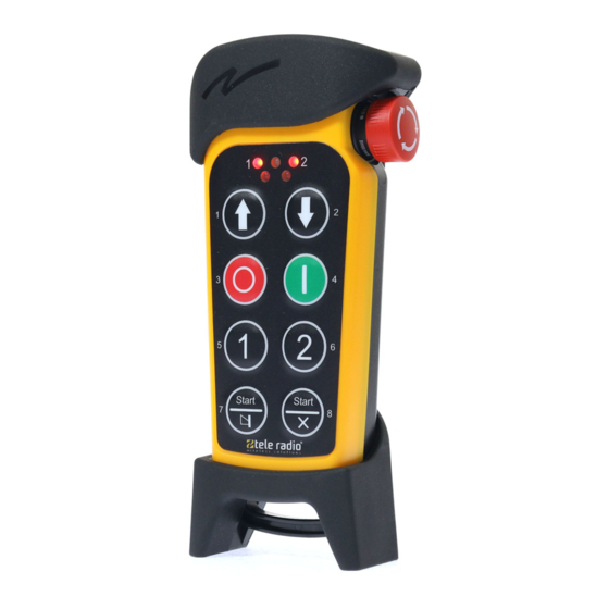
Installation instructions│ T19│ Chapter 5: Product general description CHAP TER 5: P RO D UCT G ENERAL DESCRIP TIO N The pictures shown in this chapter are for illustrative purposes only. 5 .1 T ran s m it t er f ro n t 1. -
Page 19: Transmitter Back
Installation instructions│ T19│ Chapter 5: Product general description 5 .2 T ran s m it t er b ac k 1. Rubber cover 4. Replace ID label (under the rubber cover) 2. Stop button 5. Product label (inside the battery compartment) 3. -
Page 20: Chapter 6: Error Indications And Code Messages
Installation instructions│ T19│ Chapter 6: Error indications and code messages CHAP TER 6 : ERRO R IND ICATIO NS AND CO D E M ESSAG ES Each error is identified by a code indicated by a LED combination including the top LED (LED 0) and LEDs 1–4. -
Page 21: Chapter 7: Operation
Installation instructions│ T19│ Chapter 7: Operation CHAP TER 7 : O P ERATIO N 7 .1 G en eral in f o rm at io n 7 . 1 . 1 RE C E I V E RS W I T H L O G I N / L O G O UT F UN C T I O N A C T I V A T E D To control a receiver, the transmitter must be registered and logged in to the receiver. -
Page 22: Radio Mode
Installation instructions│ T19│ Chapter 7: Operation 7 .2 Radio m o de NOTE: To establish a radio link between the transmitter and the receiver, both units must be set to the same radio mode. This transmitter is set to continuous radio mode by default. The transmitter starts to transmit continuously as soon as it is started. -
Page 23: Functionality Test
7 .3 F u n c t io n al it y t es t NOTE: This list is intended for use as a support for the manufacturer of the equipment where Tele Radio AB remote control systems are installed. Before operating the radio system, follow the procedure below. -
Page 24: Start A Session
Installation instructions│ T19│ Chapter 7: Operation 7 .4 S t art a s es s io n To be able to control a receiver with the transmitter, the transmitter must be registered in the receiver. When starting the transmitter, it will automatically log in to the receiver(s) it has been registered in, provided that no other transmitter is already logged in to the receiver(s). -
Page 25: Log The Transmitter Out From A Receiver
Installation instructions│ T19│ Chapter 7: Operation 7 .5 Lo g t h e t ran s m it t er o u t f ro m a rec eiver IMPORTANT! For the logout function to work, BOTH the receiver and the transmitter must have the logout function activated and be set to continuous radio mode. -
Page 26: Switch The Transmitter Off
Installation instructions│ T19│ Chapter 7: Operation 7 .6 S w it c h t h e t ran s m it t er o f f NOTE: When the transmitter is switched off, it remains logged in to the receiver(s). To logout, see the section "7.5 ... -
Page 27: Chapter 8: Configuration Menu
Installation instructions│ T19│ Chapter 8: Configuration menu CHAP TER 8: CO NFIG URATIO N M ENU 8 .1 Regis t er t h e t ran s m it t er in a rec eiver NOTE: The registration instructions require access to the receiver circuit board. Before starting the registration of a transmitter, prepare the receiver as follow: RISK OF ELECTRIC SHOCK The receiver must only be opened by qualified installers or authorized... - Page 28 Installation instructions│ T19│ Chapter 8: Configuration menu NOTE: To establish a radio link between the transmitter and the receiver, both units must be set to the same radio mode. 1. Make sure that the Stop button is pressed. 2. Twist and release the Stop button. The top LED lights.
-
Page 29: Menu Mode And Standard Settings
Installation instructions│ T19│ Chapter 8: Configuration menu 8 .2 M en u m o de an d s t an dard s et t in gs The Menu mode allows for certain settings to be set directly from the transmitter. Once in Menu mode, the following menus will be available. -
Page 30: Enter Menu Mode
If the code is invalid, the transmitter turns off. Go back to step 1 and try again. WITHIN 1 MINUTE OF ENTERING THE CODE: 6. Select a menu by pressing a button according to the following table. Menu T19-02 Radio mode Button 1 Replace Button 3 Show channel... -
Page 31: Select A Radio Mode On The Transmitter
6. Press button 1 to enter the [Radio mode] menu. The top LED lights (green). LED 2 flashes (red). 7. Select the radio mode by pressing a button according to the following table. Radio mode T19-02 Continuous (default) Button 1 Discontinuous Button 2 The top LED flashes (green) 3 times. -
Page 32: Replace A Transmitter
Installation instructions│ T19│ Chapter 8: Configuration menu 8 .5 Rep l ac e a t ran s m it t er It is possible to replace a registered transmitter with another transmitter of the same model. The procedure does not require to open the receiver housing but the receiver needs to be powered up and within transmission range. - Page 33 Installation instructions│ T19│ Chapter 8: Configuration menu 1. Make sure that the Stop button is pressed. 2. Press and hold button 8. 3. Twist and release the Stop button. 4. Release button 8. The top LED flashes (green). WITHIN 1 MINUTE OF RELEASING THE STOP BUTTON: 5.
-
Page 34: Show Current Radio Frequency Channel
Installation instructions│ T19│ Chapter 8: Configuration menu 8 .6 S h o w c u rren t radio f requ en c y c h an n el 1. Make sure that the Stop button is pressed. 2. Press and hold button 8. 3. -
Page 35: Set The Radio Inactivity Timeout (Automatic Shutdown)
6. Press button 5 to enter the [Automatic shutdown] menu. The top LED lights (green). LED 2 flashes (red). 7. Select the automatic shutdown time by pressing a button according to the following table. Automatic shutdown time T19-02 3 minutes Button 1 6 minutes Button 2... -
Page 36: Load Select Mode
The top LED lights (green). LED 2 flashes (red). 7. Select a Load select mode by pressing a button according to the following table. Load select mode Default load selected at start-up T19-02 Button 1 Button 2 Button 3 Button 4... - Page 37 Installation instructions│ T19│ Chapter 8: Configuration menu 8 . 8 . 1 L O A D S E L E C T M O D E 0 – 4 Load select mode 0 Load select mode 1 Load select mode 2 Load select mode 3 Load select mode 4 ...
-
Page 38: Logout From Menu Mode
Installation instructions│ T19│ Chapter 8: Configuration menu 8 .9 Lo go u t f ro m M en u m o de This logout option is mainly used when the button for quick logout is used by another function. IMPORTANT! For the logout function to work, BOTH the receiver and the transmitter must have the logout function activated and be set to continuous radio mode. -
Page 39: Select A Radio Frequency Channel
[Switch channel] menu. 10. Enter the first digit of the new channel (11–26) by pressing the buttons according to the following table. Digit T19-02 1–6 Buttons 1–6 Press and hold button 8 (shift) + press button 1 Press and hold button 8 (shift) + press button 2... - Page 40 Installation instructions│ T19│ Chapter 8: Configuration menu 11. Enter the second digit. LED 4 lights (red) when a valid digits has been entered. The top LED flashes (green) 3 times. The transmitter turns off. To check that the channel has been properly changed, follow the "8.6 ...
-
Page 41: Load At Start-Up
The top LED lights (green). LED 2 flashes (red). The transmitter enters the [Load at start-up] menu. 10. Select the load at start-up by pressing a button according to the following table. Load at start-up T19-02 Button 1 Button 2 Button 3 none Button 7 The top LED flashes (green) 3 times. -
Page 42: Chapter 9: Battery
Installation instructions│ T19│ Chapter 9: Battery CHAP TER 9 : BATTERY 9.1 Bat t ery p rec au t io n s Carefully read the following safety instructions and warnings before using, charging or disposing of the batteries. Batteries contain flammable substances such as lithium or other organic solvents, which may result in overheating, rupture or combustion. - Page 43 Installation instructions│ T19│ Chapter 9: Battery 9 . 1 . 2 D I S P O S A L When discarding batteries, insulate the + and - terminals of batteries with insulating/ masking tape. Do not place multiple batteries in the same plastic bag. ...
-
Page 44: Battery Information
Installation instructions│ T19│ Chapter 9: Battery 9.2 Bat t ery in f o rm at io n NOTE: Only batteries approved by Tele Radio AB should be used in T19 transmitters. NOTE: When approximately 10 % of the battery capacity remains, the Top LED will light red. - Page 45 9 . 2 . 1 C H A N G E T H E B A T T E RI E S I N B A T T E RY P A C K D 4 -3 Do not charge battery pack D4-3 in the Tele Radio AB charger unit or in any other charger.
-
Page 46: Chapter 10: Foils
Installation instructions│ T19│ Chapter 10: Foils CHAP TER 1 0: FO IL S Foils are used to customized transmitters depending on the application. Tele Radio AB foils are made of durable, soft, flexible GO-PU/SM polyurethane film with a semi-matt surface on the front side. -
Page 47: Chapter 11: Warranty, Service, Repairs, And Maintenance
Tele Radio AB products are covered by a warranty against material, construction and manufacturing faults. During the warranty period, Tele Radio AB may replace the product or faulty parts. Work under warranty must be performed by Tele Radio AB or by an authorized service center specified by Tele Radio AB. -
Page 48: Chapter 12: Regulatory Information
T19-02 1 2 . 1 . 1 C E M A RK I N G Hereby, Tele Radio AB, declares that the radio equipment type(s) listed above is/ are in compliance with the Radio Equipment Directive 2014/53/EU. The latest version of the complete EU Declaration of Conformity is available on the Tele Radio AB website, www.tele-radio.com. -
Page 49: North America
1 2 .2 No rt h A m eric a Applies to: T19-02 1 2 . 2 . 1 F C C S T A T E M E N T This device complies with part 15 of the FCC Rules. Operation is subject to the... - Page 50 Installation instructions│ T19│ Chapter 12: Regulatory information Le présent appareil est conforme aux CNR d’Industrie Canada applicables aux appareils radio exempts de licence. L’exploitation est autorisée aux deux conditions suivantes : 1. l’appareil ne doit pas produire de brouillage; 2. l’appareil doit accepter tout brouillage radioélectrique subi, même si le brouillage est susceptible d’en compromettre le fonctionnement.
-
Page 51: Brazil
Applies to: T19-02 1 2 . 3 . 1 A N A T E L S T A T E M E N T ( D E C L A RA Ç Ã O A N A T E L ) Este equipamento não tem direito à... -
Page 52: Annex A: Glossary
Installation instructions│ T19│ Annex A: Glossary ANNEX A: G L O SSARY Diagnostic Coverage Failures in time (1 FIT = 1 failure per 10^9 hours) Hardware Fault Tolerance MTTF Mean Time To Failure Probability of Failure per Hour Performance level Safety Failure Fraction Safety Integrity Level IM-PN-TX103-EN-v07... -
Page 53: Annex B: Index
Installation instructions│ T19│ Annex B: Index ANNEX B: IND EX AEC Statement ANATEL Statement Automatic shutdown Battery Battery information Change batteries in battery pack D4-3 Charge Battery precautions Handling Storage Charging temperature Configuration menu Dimensions Disposal EIRP FCC statement FCC/IC labels Foils Functionality test IM-PN-TX103-EN-v07... - Page 54 Installation instructions│ T19│ Annex B: Index IC Statement Inactivity timeout IP code Load at start-up Load select mode Log out Logout from Menu mode Quick logout M245060 Maintenance Menu mode Enter Menu mode, no PIN code Number of channels Operating temperature Operating time Power supply Radio communication...
- Page 55 Installation instructions│ T19│ Annex B: Index Radio frequency output power Radio mode Register Replace Safety Features Safety standards Select a Radio frequency Show current radio frequency channel Start a session Start the transmitter Stop button Storage temperature Battery Switch off Switch radio mode Top LED Transmitter back...
- Page 56 safe smart strong These Installation instructions are subject to change without prior notice. Download the latest Installation instructions from www.tele-radio.com .
Need help?
Do you have a question about the T19-02 and is the answer not in the manual?
Questions and answers