
Related Manuals for Tele Radio T26-01


Summary of Contents for Tele Radio T26-01
- Page 1 INSTALLATION INSTRUCTIONS Transmitters: T26-01, T26-06, T26-07, T26-81 safe smart strong T 2 6 IM-PM-TX102-EN-v03 Language: English (original)
- Page 2 ©Tele Radio AB Datavägen 21 SE-436 32 Askim Sweden Phone: +46 (0)31 748 54 60...
-
Page 3: Table Of Contents
CHAPTER 1: INTRODUCTION 1.1 About this document 1.2 About this system CHAPTER 2: SAFETY 2.1 Warnings & restrictions 2.2 Safety features CHAPTER 3: FUNCTIONAL SAFETY CHAPTER 4: TECHNICAL DATA 4.1 System specifications 4.2 Transmitter specifications CHAPTER 5: PRODUCT GENERAL DESCRIPTION 5.1 Overview 5.2 Transmitter dimensions 5.3 Transmitter top views 5.4 Transmitter bottom views 5.5 Transmitter side views 5.6 Display and display LEDS... - Page 4 8.8 Switch the transmitter off CHAPTER 9: CONFIGURATION MENU 9.1 Menu mode and standard settings 9.2 Enter Menu mode (no PIN code required) 9.3 Enter Menu mode (PIN code required) 9.4 Register a transmitter in a receiver 9.5 Erase a transmitter from a receiver 9.6 Replace a transmitter 9.7 Clear blocked inputs 9.8 Select a radio frequency channel 9.9 Set the backlight intensity...
-
Page 5: Chapter 1: Introduction
The Installation instructions may be withdrawn or revised by Tele Radio AB at any time and without further notice. Corrections and updates will be added to the latest version of the manual. Always download the Installation instructions from our website, www.tele-radio.com, for the latest available version. - Page 6 For battery precautions, see "10.1 Battery precautions". Tele Radio AB products are covered by a warranty against material, construction, or manufacturing faults. See "Chapter 11: Warranty, service, repairs, and maintenance". IM-PM-TX102-EN-v03...
-
Page 7: About This Document
Before installing or operating the product, read the corresponding documentation carefully. Tele Radio AB's product range is composed of transmitters, receivers, and accessories intended for use together as a system. T26 systems are mainly intended for the hydraulic and mobile equipment markets. -
Page 8: About This System
Each customized system has its own generated system number. It is important to keep this number and to use it in all communication with Tele Radio AB. The label with the system number (System No.) is affixed on the product's original label. - Page 9 Transmitters can be customized using a Web Configuration App. The Web Configuration App is a user-friendly, web-based tool for simple customization and configuration of Tele Radio AB's transmitters. It has an intuitive user interface and allows the trained technician to perform all sorts of customization.
- Page 10 Installation instructions│ T26│ Chapter 1: Introduction All information on how to use the Web Configuration App can be found in the application itself or in the corresponding documentation (ED-WB-DX101). IM-PM-TX102-EN-v03...
-
Page 11: Chapter 2: Safety
IMPORTANT! Tele Radio AB remote controls are often built into wider applications. These systems should be equipped with: • a wired emergency stop where necessary ... - Page 12 Installation instructions│ T26│ Chapter 2: Safety When the equipment controlled by the receiver's standard relays is connected via the stop relays, make sure that the maximum current through the stop relays is still within the specifications. Contact your representative for assistance. RISK OF UNINTENDED EQUIPMENT OPERATION Only transmitters that are intended for use should be registered in the receiver.
- Page 13 Installation instructions│ T26│ Chapter 2: Safety Always test the transmitter stop button before operating it.This test should be done on each shift, without a load. See "2.2.1 Stop button". Never use a transmitter if the stop button is mechanically damaged.Contact your supervisor or representative for service immediately.
-
Page 14: Safety Features
Installation instructions│ T26│ Chapter 2: Safety 2 .2 S af et y f eat u res 2 . 2 . 1 S T O P B UT T O N When the Stop button is pressed, the safety relays on the receiver deactivate, unless otherwise stated in the corresponding technical documentation provided with each customized system. -
Page 15: Chapter 3: Functional Safety
Installation instructions│ T26│ Chapter 3: Functional safety CHAP TER 3: FUNCTIO NAL SAFETY S t o p f u n c t io n The safety-related stop function in the radio system complies with EN ISO 13849- 1:2015 Category 3 PL d. The stop relays on the receiver unit are controlled by the stop button on the transmitter unit. - Page 16 Installation instructions│ T26│ Chapter 3: Functional safety A c h ieved p erf o rm an c e l evel ( P L) Safety function MTTFd (years) DCavg(%) Category Achieved PL Stop function IM-PM-TX102-EN-v03...
-
Page 17: Chapter 4: Technical Data
Installation instructions│ T26│ Chapter 4: Technical data CHAP TER 4: TECHNICAL D ATA NOTE: The information below may differ in customized systems, please refer to the corresponding technical documentation provided with each system. 4.1 S y s t em s p ec if ic at io n s Radio frequency band 2405 –... - Page 18 Active & redundant stop function Redundant joystick and switch enabled IP code IP65 4 . 2 . 2 O T H E R S P E C I F I C A T I O N S T26-01 T26-06 T26-07 T26-81 ○ ○...
- Page 19 Installation instructions│ T26│ Chapter 4: Technical data J o y s t ic k d ir ec t io n s T26-81 transmitters have two joysticks (2-axis with spring-to-centre) allowing a stepless control. T26-81 Joystick 1 (XY) Analog XY Joystick 2 (XY) Analog XY ...
-
Page 20: Chapter 5: Product General Description
Installation instructions│ T26│ Chapter 5: Product general description CHAP TER 5: P RO D UCT G ENERAL DESCRIP TIO N NOTE: The pictures shown in this chapter are for illustrative purposes only. Depending on the configuration, the actual product appearance may differ from the basic model used for reference. -
Page 21: Transmitter Top Views
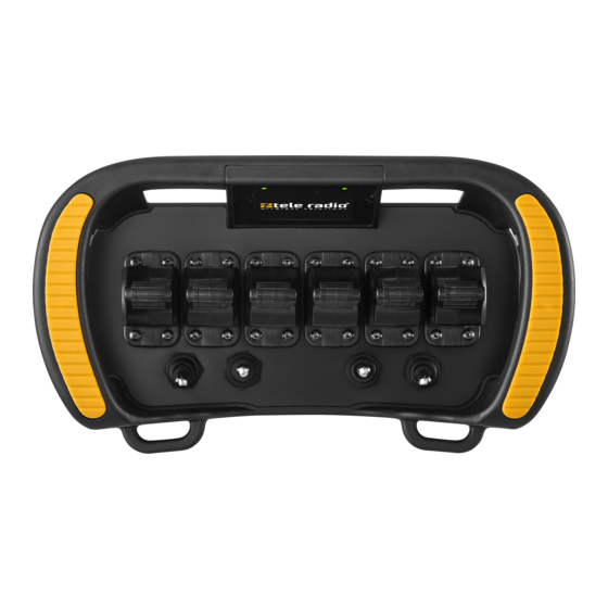
Installation instructions│ T26│ Chapter 5: Product general description 5 .3 T ran s m it t er t o p view s 5 . 3 . 1 T 2 6 -0 1 1. Handlebar 3. LCD display 5. Customizable area 2. - Page 22 Installation instructions│ T26│ Chapter 5: Product general description 5 . 3 . 3 T 2 6 -8 1 1. Handlebar 4. Battery LED 6. Belt loops 2. Status LED 5. Joysticks 1–2 7. Toggle switches 1–3 3. LCD display With integrated LEDs. IM-PM-TX102-EN-v03...
-
Page 23: Transmitter Bottom Views
Installation instructions│ T26│ Chapter 5: Product general description 5 .4 T ran s m it t er b o t t o m view s 5 . 4 . 1 T 2 6 -0 1 , T 2 6 -8 1 4. - Page 24 Installation instructions│ T26│ Chapter 5: Product general description 5 . 4 . 2 T 2 6 -0 6 , T 2 6 -0 7 4. Customizable area 1. Customizable area 6. RFID antenna (e.g. for the stop (e.g. for a key switch) (configurable option) button) 2.
-
Page 25: Transmitter Side Views
Installation instructions│ T26│ Chapter 5: Product general description 5 .5 T ran s m it t er s ide view s 5 . 5 . 1 T 2 6 -0 1 Left side Right side 1. LCD display 4. - Page 26 Installation instructions│ T26│ Chapter 5: Product general description 5 . 5 . 2 T 2 6 -0 6 , T 2 6 -0 7 Left side Right side 1. LCD display 4. SB2 7. Customizable area (e.g. for a key switch) 2.
- Page 27 Installation instructions│ T26│ Chapter 5: Product general description 5 . 5 . 3 T 2 6 -8 1 Left side Right side 1. SB1 5. Toggle switches 1–3 8. Belt loops 2. LCD display 6. SB2 9. Key switch 3. Handlebar 7.
-
Page 28: Display And Display Leds
Installation instructions│ T26│ Chapter 5: Product general description 5 .6 D is p l ay an d dis p l ay LE D S The transmitter is equipped with two LEDs providing information about battery level, radio link status and other status (see the LEDs status and error codes in the table below). -
Page 29: Side Buttons
Installation instructions│ T26│ Chapter 5: Product general description W a r n in g m es s a g es ”Warning” messages are shown on a yellow background and indicate a warning message that will vanish after a short moment. ... -
Page 30: Chapter 6: Board Description
Installation instructions│ T26│ Chapter 6: Board description CHAP TER 6 : BO ARD D ESCRIP TIO N NOTE: The pictures shown in this chapter are for illustrative purposes only. IMPORTANT! Only experienced electronic technicians should add and map expansion boards and inputs/outputs. 6.1 ... - Page 31 Installation instructions│ T26│ Chapter 6: Board description Board position number Board description Base board Bottom board for battery Slot for expansion boards* Circuit board for the display RFID module Circuit board boards for the LEDs in the handlebar Circuit board boards for the LEDs in the handlebar Radio module 2.4 GHz Bluetooth module *Possible expansion boards are e.g.
-
Page 32: Base Board
Installation instructions│ T26│ Chapter 6: Board description 6.2 Bas e b o ard NOTE: This base board is integrated in all T26 models. It has position number A. 1. Connector for LEDs on the 9. Connector for alternative stop handlebar button 2. -
Page 33: Bottom Board
Installation instructions│ T26│ Chapter 6: Board description 6.3 Bo t t o m b o ard NOTE: This board is integrated in all T26 models. It has position number B. 1. Connector for standard stop 4. Connector for key switch (beneath) button 5. -
Page 34: Expansion Boards
Installation instructions│ T26│ Chapter 6: Board description 6.4 E xp an s io n b o ards NOTE: Expansion boards can be fitted in position C. Expansion boards can be used to increase the number of inputs/outputs and communication options. There are currently three expansion boards available for the T26 transmitters. - Page 35 Installation instructions│ T26│ Chapter 6: Board description 6 . 4 . 1 E X P A N S I O N B O A RD F O R E X T RA I / O S NOTE: This board can be integrated into all T26 models. ...
- Page 36 Installation instructions│ T26│ Chapter 6: Board description DIO connector (J4) Description +V_CTRLABLE DIG23 DIG24 DIO connector (J5) Description +V_CTRLABLE DIG27 DIG28 DIO connector (J6) Description +V_CTRLABLE DIG37 DIG38 IM-PM-TX102-EN-v03...
- Page 37 Installation instructions│ T26│ Chapter 6: Board description 6 . 4 . 2 E X P A N S I O N B O A RD F O R P A D D L E I / O S NOTE: This board can be integrated into all T26 models. ...
- Page 38 Installation instructions│ T26│ Chapter 6: Board description Paddle connector (J2) Description Description – V+ (CTRLABLE) P2-M1 P2-V1 P2-M2 P2-V2 V+ (CTRLABLE) – Paddle connector (J3) Description Description – V+ (CTRLABLE) P3-M1 P3-V1 P3-M2 P3-V2 V+ (CTRLABLE) – Paddle connector (J4) Description Description –...
- Page 39 Installation instructions│ T26│ Chapter 6: Board description 6 . 4 . 3 E X P A N S I O N B O A RD F O R H A L L E F F E C T J O Y S T I C K I / O S NOTE: This board can be integrated into all T26 models.
- Page 40 Installation instructions│ T26│ Chapter 6: Board description A/D connector (J3) Description Description AD3X2 AD3X1 AD3Z2 AD3Y2 V+ (+5 V) AD3Y1 AD3Z1 C u r r en t c o n s u m p t io n o f H a l l J o y s t ic k s Joystick axis Current consumption XY-axis...
-
Page 41: Chapter 7: Status And Error Indications
Installation instructions│ T26│ Chapter 7: Status and error indications CHAP TER 7 : STATUS AND ERRO R INDICATIO NS 7 .1 D is p l ay LE D s s t at u s an d erro r c o des Colour Flash Indicates ●... -
Page 42: Chapter 8: Operation
Installation instructions│ T26│ Chapter 8: Operation CHAP TER 8: O P ERATIO N 8 .1 G en eral in f o rm at io n To control a receiver, the transmitter must be registered and logged in to the receiver. -
Page 43: Start-Up Protection
Installation instructions│ T26│ Chapter 8: Operation 8 . 2 . 2 E N T E R N UM B E RS / C H A N G E V A L UE S Side button Action SB1 (Select) Accept the updated value SB2 (Back) Cancel and go back to the menu without confirmation SB3 and SB4... -
Page 44: Functionality Test
8 .4 F u n c t io n al it y t es t NOTE: This list is intended for use as a support for the manufacturer of the equipment where Tele Radio AB remote control systems are installed. Before operating the radio system, follow the procedure below. -
Page 45: Log The Transmitter In To A Receiver
Installation instructions│ T26│ Chapter 8: Operation 8 .5 Lo g t h e t ran s m it t er in t o a rec eiver 1. Make sure that the Stop button is pressed. 2. Turn the key switch to the 'On' position (horizontal). 3. -
Page 46: Start A Session
Installation instructions│ T26│ Chapter 8: Operation 8 .6 S t art a s es s io n To be able to control a receiver using the transmitter, the transmitter must be registered and logged in to a receiver. When not in use, transmitters must be switched off and stored in a secure storage space. - Page 47 Installation instructions│ T26│ Chapter 8: Operation The display shows: and the list of registered [Select one or more items] receivers. Selected receivers are marked with a + sign. If the correct receiver is already selected Press the Back button. The display returns to the start screen: [Session Selection] ...
-
Page 48: Log The Transmitter Out From A Receiver
Installation instructions│ T26│ Chapter 8: Operation 8 .7 Lo g t h e t ran s m it t er o u t f ro m a rec eiver A transmitter already logged in to the receiver has to be logged out before any other transmitter can be logged in. -
Page 49: Chapter 9: Configuration Menu
Installation instructions│ T26│ Chapter 9: Configuration menu CHAP TER 9 : CO NFIG URATIO N M ENU 9.1 M en u m o de an d s t an dard s et t in gs The Menu mode allows for certain settings to be set directly from the transmitter. Once in Menu mode, the following menus will be available. -
Page 50: Enter Menu Mode (No Pin Code Required)
Installation instructions│ T26│ Chapter 9: Configuration menu 9 . 1 . 1 M E N U M O D E P RO T E C T I O N PIN codes can be activated to prevent unauthorized personnel from entering the Menu mode. -
Page 51: Enter Menu Mode (Pin Code Required)
Installation instructions│ T26│ Chapter 9: Configuration menu 9.3 E n t er M en u m o de ( P IN c o de requ ired) 1. Make sure that the Stop button is pressed. 2. Turn the key switch to the 'On' position (horizontal). 3. -
Page 52: Register A Transmitter In A Receiver
Installation instructions│ T26│ Chapter 9: Configuration menu 9.4 Regis t er a t ran s m it t er in a rec eiver Registering means establishing communication between the transmitter and the receiver. T26 transmitters can have up to 32 registered receivers (locations 1–32). NOTE: The registration instructions require access to the receiver housing. - Page 53 Installation instructions│ T26│ Chapter 9: Configuration menu On the Receiver On the Transmitter 4. Make sure that the Stop button is pressed. 5. Turn the key switch to the 'On' position (horizontal). 6. Twist and release the Stop button. The initial start-up logo is displayed.Battery indicator(s) light 1.
- Page 54 Installation instructions│ T26│ Chapter 9: Configuration menu The transmitter is now registered. On the Receiver On the Transmitter LED 1 is flashing (slow). The transmitter turns off. If not successfully completed: On the Receiver On the Transmitter The receiver exits registration mode. The display shows: [Registration LED 1 is flashing (red).If Bluetooth has...
-
Page 55: Erase A Transmitter From A Receiver
Installation instructions│ T26│ Chapter 9: Configuration menu 9.5 E ras e a t ran s m it t er f ro m a rec eiver This procedure erases the transmitter from the receiver and vice versa. NOTE: The receiver must be powered up for the Erase procedure to be successful. 1. -
Page 56: Replace A Transmitter
Installation instructions│ T26│ Chapter 9: Configuration menu 9.6 Rep l ac e a t ran s m it t er It is possible to replace a registered transmitter with another transmitter. The procedure does not require to open the receiver housing but the receiver needs to be powered up and within transmission range. -
Page 57: Clear Blocked Inputs
Installation instructions│ T26│ Chapter 9: Configuration menu 9.7 C l ear b l o c k ed in p u t s On start up, the T26 transmitters perform a zero position check for control switches, joysticks and/or paddles. If the transmitter detects that some control [One or more inputs are not commands are not in the zero position, the... -
Page 58: Select A Radio Frequency Channel
Installation instructions│ T26│ Chapter 9: Configuration menu 9.8 S el ec t a radio f requ en c y c h an n el To change radio channel: 1. Make sure that the Stop button is pressed. 2. Turn the key switch to the 'On' position (horizontal). 3. -
Page 59: Set The Backlight Intensity
Installation instructions│ T26│ Chapter 9: Configuration menu 9.9 S et t h e b ac k l igh t in t en s it y Set the LCD screen luminosity level (in %). 1. Make sure that the Stop button is pressed. 2. -
Page 60: Set The Buzzer Volume
Installation instructions│ T26│ Chapter 9: Configuration menu 9.1 0 S et t h e b u zzer vo l u m e Set the buzzer volume level (in %). 1. Make sure that the Stop button is pressed. 2. -
Page 61: Set The Radio Inactivity Timeout
Installation instructions│ T26│ Chapter 9: Configuration menu 9.1 1 S et t h e radio in ac t ivit y t im eo u t Set the off delay (in seconds) before the transmitter automatically turns off. 1. Make sure that the Stop button is pressed. 2. -
Page 62: Select A Time Zone
Installation instructions│ T26│ Chapter 9: Configuration menu 9.1 2 S el ec t a t im e zo n e Set the time zone (UTC +/- 14 h). 1. Make sure that the Stop button is pressed. 2. Turn the key switch to the 'On' position (horizontal). 3. -
Page 63: Register Rfid Tags
Installation instructions│ T26│ Chapter 9: Configuration menu 9.1 3 Regis t er RF ID t ags NOTE: If the RFID functions are not activated, contact your representative for assistance. 1. Make sure that the Stop button is pressed. 2. -
Page 64: Erase Rfid Tags
Installation instructions│ T26│ Chapter 9: Configuration menu 9.1 4 E ras e RF ID t ags 1. Make sure that the Stop button is pressed. 2. Turn the key switch to the 'On' position (horizontal). 3. Twist and release the Stop button. The initial start-up logo is displayed. -
Page 65: Configure Repeater Slot Id
Installation instructions│ T26│ Chapter 9: Configuration menu 9.1 5 C o n f igu re rep eat er s l o t ID The slot ID corresponds to the position of a repeater in a chain of one to up to fifteen repeaters (0–14). - Page 66 Installation instructions│ T26│ Chapter 9: Configuration menu 8. Press the Select button to Go back to step 1 and try again. enter. The display shows: [Range 0– 14] [Value:XX] 9. Change the slot ID (1–14) using the Up/Down buttons. 10. Press the Select button to confirm.
-
Page 67: Show The Device Information
The display shows: [S/N: HY-TXXXX]* [CPU01: XXXX] … * S/N = serie number; HY= Tele Radio AB's internal product code; TX= transmitter ** CPU01–04: Id number of the software currently used in each of the transmitter's CPU cards. IM-PM-TX102-EN-v03... -
Page 68: Chapter 10: Battery
Installation instructions│ T26│ Chapter 10: Battery CHAP TER 1 0: BATTERY 1 0 .1 Bat t ery p rec au t io n s Carefully read the following safety instructions and warnings before using, charging or disposing of the batteries. Batteries contain flammable substances such as lithium or other organic solvents, which may result in overheating, rupture or combustion. - Page 69 Installation instructions│ T26│ Chapter 10: Battery 1 0 . 1 . 2 D I S P O S A L When discarding batteries, insulate the + and - terminals of batteries with insulating/ masking tape. Do not place multiple batteries in the same plastic bag. ...
-
Page 70: Battery Information
LED will flash red /green alternatively (appears orange) with an interval ON=100 ms and OFF=900 ms. The battery can be recharged using a Tele Radio AB battery charger (e.g. table charger or car cigarette lighter adapter) or the AC main charger adapter. - Page 71 NOTE: When approximately 10 % of a battery capacity remains, the corresponding battery LED will light red. 1. Remove the battery from its compartment and place it in the Tele Radio AB battery charger. 2. The charger's LED lights red while the battery is charging.
-
Page 72: Chapter 11: Warranty, Service, Repairs, And Maintenance
Tele Radio AB products are covered by a warranty against material, construction and manufacturing faults. During the warranty period, Tele Radio AB may replace the product or faulty parts. Work under warranty must be performed by Tele Radio AB or by an authorized service center specified by Tele Radio AB. -
Page 73: Chapter 12: Regulatory Information
T26, T26-01, T26-06, T26-07, T26-81 1 2 . 1 . 1 C E M A RK I N G Hereby, Tele Radio AB, declares that the radio equipment type(s) listed above is/ are in compliance with the Radio Equipment Directive 2014/53/EU. - Page 74 Installation instructions│ T26│ Chapter 12: Regulatory information This equipment has been tested and found to comply with the limits for a Class B digital device, pursuant to part 15 of the FCC Rules. These limits are designed to provide reasonable protection against harmful interference in a residential installation.
-
Page 75: Radio Module
Installation instructions│ T26│ Chapter 12: Regulatory information Afin d'assurer la conformité aux exigences de la IC en matière d'exposition aux RF, une distance de séparation d'au moins 20 cm doit être maintenue entre l'antenne de cet appareil et toute personne à proximité pendant le fonctionnement de l'appareil. -
Page 76: Annex A: List Of Errors And Error Messages
Information Cat. 2 messages are meant to be interpreted by personnel Technical with comprehensive knowledge of Tele Radio radio Support protocol, hardware, and settings. Depending on the message, knowledge in one or several of the areas listed below is needed: ... - Page 77 Installation instructions│ T26│ Annex A: List of errors and error messages Event code Event description Category SwCrash (1002) [ SW error caused exception handler xxxx to be called. Last task executing: xxxx, dbgWord: , SCB->SHCSR: xxxx, SCB->CFSR: xxxx, SCB->MMFAR: xxxx, SCB- >BFAR: xxxx, r0: xxxx, r1: xxxx, r2: xxxx, r3: xxxx, r12: xxxx, lr: xxxx, pc:...
- Page 78 Installation instructions│ T26│ Annex A: List of errors and error messages Event code Event description Category ErrorLoginUnusedRxRegIdxReferenced [ An unused RX registration (1011) index, xxxx, was used as reference at login ] ErrorRegistrationInvalidArgs (1020) [ A registration was ordered to an already used RX registration index (xxxx) ] ErrorReplaceTxMemoryFull (1025) [ A replace was ordered when...
- Page 79 Installation instructions│ T26│ Annex A: List of errors and error messages Event code Event description Category CapSensorEnteringAtiDuringInit (1051) [ Cap sensor entering ATI during init, sensor index: xxxx ] CapSensorEnteringAtiSpontaneously (1052) [ Cap sensor entering ATI spontaneously, sensor index: xxxx ] CapSensorLeavingATI (1053) [ Cap sensor leaving ATI, sensor index: xxxx ]...
- Page 80 Installation instructions│ T26│ Annex A: List of errors and error messages Event code Event description Category ChargerBatterySelection (1073) [ Battery xxxx selected for charging ] ChargingReport (1074) [ Charging report, current charger voltage (milli- volts): xxxx, current battery voltage (milli-volts): xxxx, batSupervisionStatus: xxxxxx, batChargingStatus: xxxxxx ] ChargingErrorBadBattery (1075)
- Page 81 Installation instructions│ T26│ Annex A: List of errors and error messages Event code Event description Category 2hw (sw SafetyCpuInBootloader (1140) [ Safety CPU is in needs to bootloader, no valid firmware loaded ] flashed again) SafetyCpuNoResponseToCpuQuery (1141) [ Safety CPU did not respond to CPU query ] SafetyCpuNoResponseToVersionQuery [ Safety CPU did not respond...
- Page 82 Installation instructions│ T26│ Annex A: List of errors and error messages Event code Event description Category StopButtonAdcInvalidValue (1162) [ The AD converter used to measure the stop button state measured an invalid value ] StopButtonInconsistentBranchesDetectedByCpu2 [ According to CPU2 the two (1163) branches of the stop button does not agree about the...
- Page 83 Installation instructions│ T26│ Annex A: List of errors and error messages Event code Event description Category StopButtonDataFromCpu2Incorrect (1173) [ The aggregated stop button bit from CPU2 indicate that CPU2 thinks the stop button is pulled when ES1 and ES2 indicate pushed or inconsistent ] CheckOfSafeDataInRadioPacketFailed [ The safe data in radio...
- Page 84 Installation instructions│ T26│ Annex A: List of errors and error messages Event code Event description Category 2hw (sw IoBoardInvalidSwVersion (1188) [ IO board with trabus needs to address xxxx has invalid SW version ] flashed again IoBoardFailedToStartCommunication (1189) [ Failed to start IO board communication, entering trabus level 2X ] IoBoardFailedToStopCommunication (1190)
- Page 85 Installation instructions│ T26│ Annex A: List of errors and error messages Event code Event description Category IoBoardFailedToGetHwConfigId (1198) [ IO board with trabus address xxxx failed to report any HW configuration identifier ] IoBoardInvalidHwConfigId (1199) [ IO board with trabus address xxxx reported invalid HW configuration identifier ] IoBoardUnsupportedHwConfigId (1200)
- Page 86 Installation instructions│ T26│ Annex A: List of errors and error messages Event code Event description Category IoBoardSomeSafetyCpuDead (1206) [ One or more safety CPU is reported dead ] IoBoardFailedGetIsSafetyCpuDead (1207) [ Failed to retrieve info from IO-boards with trabus address xxxx when trying to find out if safety CPU is dead ] IoBoardSafetyCpuDead (1208)
- Page 87 Installation instructions│ T26│ Annex A: List of errors and error messages Event code Event description Category Tr430IoAdConversionFailed (1222) [ The IO AD conversion on TR430 failed ] Tr430IoFailedToCompleteInitPhase (1223) [ The IO init phase on TR430 main board failed to finish on time ] Tr430BrokenSensor (1224) [ Sensor(s) on pin(s)
- Page 88 Installation instructions│ T26│ Annex A: List of errors and error messages Event code Event description Category RfidScanBatteryErrorNotAtex (1264) [ RFID: The system requires ATEX batteries but we found a battery in slotIdx: xxxxwhich is not ATEX ] RfidScanBatteryErrorIncorrectOemId (1265) [ RFID: Mismatch between battery OemID and settings.
- Page 89 Installation instructions│ T26│ Annex A: List of errors and error messages A . 1 . 1 # S Y S T E M E V E N T S Event code Event description Category SystemPowerDown (1370) [ System is powering down ] IoBlockRequestSystemRestart [ IO module requests system restart ] (1371)
- Page 90 Installation instructions│ T26│ Annex A: List of errors and error messages Event code Even description Category RepeaterConfigrationEnterSuccessful [ Repeater (rptId = xxxx) (1392) replied and has entered configuration mode ] RepeaterConfigurationExit (1393) [ CPU3 initiated repeater config exit: saveSettings = xxxx ] RepeaterConfigurationTimedOut (1394) [ Repeater configuration...
-
Page 91: A.2 Events And Error Events Nº 2000 - 2110
Installation instructions│ T26│ Annex A: List of errors and error messages Event code Even description Category Trabus3RequestSystemRestart (1500) [ Trabus3 module requests system restart ] Trabus3LeavingBreakMode (1501) [ Trabus3 module leaves break mode (system restart will take place) ] Trabus3LeavingConfigMode (1502) [ Trabus3 module leaves config mode (system restart will take place) ]... - Page 92 Installation instructions│ T26│ Annex A: List of errors and error messages Event code Event description Category ErrorLoginOtherTxLoggedIn (2004) [ Login failed, TX-id xxxx is logged in to RX-id: xxxx ErrorLoginSessionActive (2005) [ Login failed, TX-id xxxx has an active session in RX-id: xxxx ] ErrorLoginReqTxProtocolVersionNotSupported [ Login failed, TX protocol...
- Page 93 Installation instructions│ T26│ Annex A: List of errors and error messages Event code Event description Category EndRadioSessionDueToInactivity (2015) [ End session requested due to inactivity when radio session is active ] EndRadioSessionUserRequested (2016) [ End session requested due to user request ] EndRadioSessionEmergency (2017) [ End session, emergency ] RegistrationProcedureStarted (2018)
- Page 94 Installation instructions│ T26│ Annex A: List of errors and error messages Event code Event description Category ErrorRegistrationUnhandledReplyStatus [ Registration failed, (2053) status in reply from RX unknown, RX-id: xxxx ] ErrorRegistrationConfigIdMismatch (2054) [ Registration failed, config-ID missmatch, RX-id: xxxx ] OkRegistration (2055) [ Registration OK, RX-id: xxxx ]...
-
Page 95: A.3 Events And Error Events Nº 1454 - 1493
Installation instructions│ T26│ Annex A: List of errors and error messages Event code Event description Category SessionMasterTakeover (2080) [ This login will cause a session takover as master from TX-id xxxx in RX-id xxxx ] SessionPcTakeover (2081) [ This login will cause a session takover with pitch/catch from TX-id xxxx in RX-id xxxx ]... - Page 96 Installation instructions│ T26│ Annex A: List of errors and error messages Event description Event code Category BtMcuAddBondedSubIndex5 (1459) [ Bonded SubIndex5 pIdentityInfo isirk(xxxxxx) bd_addr(xxxxxx) ] BtMcuAddBondedSubIndex6 (1460) [ Bonded SubIndex6 pSigningInfo srk (xxxxxx) ] BtMcuAddBondedSubIndex7 (1461) [ Bonded BtMcuAddBondedSubIndex7 pSigningInfo singcount xxxxxx ] BtMcuAddBondedSubIndex8 (1462) [ Bonded SubIndex8 auto sync white list is xxxx ]...
- Page 97 Installation instructions│ T26│ Annex A: List of errors and error messages Event description Event code Category BtMcuPairRequest (1473) [ APP Pair request eventxxxxxx status xxxxxx opcode xxxxxx connectionHandle xxxx ioCap xxxxxx oobDataFlag xxxxxx authReq xxxxxx maxEncKeySize xxxxxx bitkeyDist xxxx] BtMcuLinkTerminated (1474) [ Link Terminate: event:xxxxxx status:xxxxxx opcode:xxxxxx connectionHandle:xxxxxx...
- Page 98 Installation instructions│ T26│ Annex A: List of errors and error messages Event description Event code Category BtMcuPherOsalEventOpcodeIndex1 [ Pheripheral osal event cmdOpcode (1484) index1: event:xxxxxx status:xxxxxx numHciCmdPkt:xxxxxx cmdOpcode:xxxx ] BtMcuPherOsalEventOpcodeIndex0 [ Pheripheral Index0 osal event (1485) index0: event:xxxxxx status:xxxxxx undef:xxxxxx-%02x-%02x-%02x ] BtMcuPherOsalEventOpcodeIndex2 [ Pheripheral Index0 osal event (1486)
-
Page 99: Annex B: Glossary
Installation instructions│ T26│ Annex B: Glossary ANNEX B: G L O SSARY Diagnostic Coverage Failures in time (1 FIT = 1 failure per 10^9 hours) Hardware Fault Tolerance MTTF Mean Time To Failure Probability of Failure per Hour Performance level Safety Failure Fraction Safety Integrity Level IM-PM-TX102-EN-v03... -
Page 100: Annex C: Index
Installation instructions│ T26│ Annex C: Index ANNEX C: INDEX Antenna Backlight intensity Base board Battery Charge BATTERY PACK Battery precautions Handling Storage Boards Bottom board Buzzer volume Capacitive sensors Channel number CHARGERS Charging temperature Circuit board positions Clear blocked inputs Compatibility IM-PM-TX102-EN-v03... - Page 101 Installation instructions│ T26│ Annex C: Index Configuration menu Enter menu mode, PIN code Connector A/D inputs/ouptuts Current consumption Data format device information Dimensions Display LEDs Display specifications Disposal EIRP Erase Expansion boards Extra I/Os Hall efect joysticks Paddle I/Os Extra I/Os FCC statement FCC/IC labels Frequency management...
- Page 102 Installation instructions│ T26│ Annex C: Index IC Statement Inactivity timeout IP code Log in Log out M245060 M769746 M769755 M769780 Maintenance Menu mode Enter Menu menu, no PIN code Menu protection Menu navigation Message categories Message types Number of channels Operating temperature PIN code Position...
- Page 103 Installation instructions│ T26│ Annex C: Index Expansion boards Main board Power supply Product label Radio frequency band Radio frequency output power Radio module Range Register Repeater Configure Replace RFID tags Erase Register Safety Features Safety standards Select a Radio frequency Serial Number Side buttons slot ID...
- Page 104 Installation instructions│ T26│ Annex C: Index Start session Status and error code messages Stop button Stop function Stop relays Storage temperature Battery Switch off System address Time zone Transmitter display Warnings & restrictions Installation and commission Maintenance Operation WEEE directive IM-PM-TX102-EN-v03...
- Page 105 Installation instructions│ T26│ This page intentionally left blank. IM-PM-TX102-EN-v03...
- Page 106 safe smart strong These Installation instructions are subject to change without prior notice. Download the latest Installation instructions from www.tele-radio.com .
Need help?
Do you have a question about the T26-01 and is the answer not in the manual?
Questions and answers