
Subscribe to Our Youtube Channel
Related Manuals for Tele Radio T26 Series


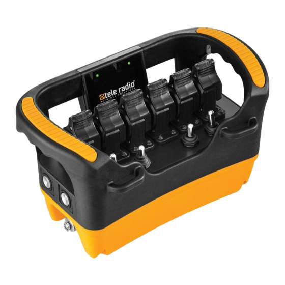
Summary of Contents for Tele Radio T26 Series
- Page 1 T26/T27 Installation instructions T26-01 Transmitters T26-06, T26-07 T26-81, T26-82 T27-01 IM-HY-TX102-A05-CERT (IM-HY-TX102-CERT-v05) Language: English (original)
-
Page 2: Table Of Contents
CHAPTER 1: INTRODUCTION About this system About this document CHAPTER 2: SAFETY Warnings & restrictions Safety features CHAPTER 3: TECHNICAL DATA System specifications Transmitter specifications CHAPTER 4: PRODUCT GENERAL DESCRIPTION Transmitter casing Transmitter dimensions T26-01 T26-06 T26-07 T26-81 T26-82 T26 bottom views T27-01 LEDs and display CHAPTER 5: OPERATION (T26) - Page 3 Battery information CHAPTER 8: WARRANTY, SERVICE, REPAIRS, AND MAINTENANCE CHAPTER 9: REGULATORY INFORMATION Europe North America Radio module...
-
Page 4: Chapter 1: Introduction
MOUNTING, INSTALLING, CONFIGURING AND OPERATING THE PRODUCTS. These installation instructions have been published by Tele Radio AB and are not subject to any guarantees. The Installation instructions may be withdrawn or revised by Tele Radio AB at any time and without further notice. -
Page 5: About This System
ABOUT THIS SYSTEM Tele Radio AB's remote control systems are suitable for a wide variety of applications for e.g. stationary or mobile equipments, hydraulic machines, construction, forestry or agriculture equipments and more. Tele Radio AB's transmitters and receivers are highly customizable and can be configured to suit the most wide-ranging application requirements &... - Page 6 Adjust the belt around the waist, then hook the transmitter into the waist belt straps. Figure 1: Working position with a Tele Radio AB transmitter while using the Tele Radio AB waist belt NOTE! Always hold the transmitter with the control panel towards you. You must be able to read any text on the control panel and understand the symbols on it.
-
Page 7: About This Document
(including photocopying), recording or otherwise for any purpose other than the purchaser's personal use without the written permission of Tele Radio AB. Term and symbol definitions... -
Page 8: Chapter 2: Safety
Installation and commission This radio system must not be used in areas where there is a risk of explosion. Tele Radio AB remote controls are often built into wider applications. These systems should be equipped with: a wired emergency stop where necessary... - Page 9 Operation Only qualified personnel should be permitted to access the transmitter and operate the equipment. Make sure that the user satisfies the age requirements in your country for operating the equipment. Make sure that the user is not under the influence of drugs, alcohol and medications.
-
Page 10: Safety Features
SAFETY FEATURES Stop button When the stop button is pressed, the safety relays on the receiver deactivate, unless otherwise stated in the corresponding technical documentation provided with each customized system. IMPORTANT! Always use the stop button in an emergency. Figure 2: Example of possible locations for the stop button. Here on the right side of a T24 and T26 transmitter. -
Page 11: Chapter 3: Technical Data
CHAPTER 3: TECHNICAL DATA NOTE! The information below may differ in customized systems, please refer to the corresponding technical documentation provided with each system. SYSTEM SPECIFICATIONS Radio frequency band 2405 – 2480 MHz Frequency management Direct Sequence Spread Spectrum (DSSS) Field Strength Adaptation Feature Number of Channels 16 (11–26) - Page 12 Other specifications T26-01 T26-06 T26-07 T26-81 T26-82 Number of joysticks 2, 2-axis with spring return for analogue control directions (see "Joystick directions" below). Number of paddles – Number of switches 3, toggle switch (On)– None–(On) (spring return) Stop button On the side No predefined position On the side Key switch Display...
- Page 13 Example: Analog XY Analog Y The joystick operates on both X and Y axes The joystick/paddle operates on the Y axe only with stepless movement from the center. with stepless movement from center and back. T27-01 Number of joysticks Number of paddles Number of switches Stop button On the side...
-
Page 14: Chapter 4: Product General Description
CHAPTER 4: PRODUCT GENERAL DESCRIPTION NOTE! The pictures shown in this chapter are for illustrative purposes only. Depending on the configuration, the actual product appearance may differ from the basic model used for reference. TRANSMITTER CASING 1. Side button 2 4. -
Page 15: T26-01
T26-01 Transmitter top view 1. Handlebars 3. LCD display 5. Customizable area 2. Status LED 4. Battery LED 6. Belt loops Transmitter side views Left side Right side 1. Side button 1 4. Side button 2 7. Side button 3 (start button) 2. -
Page 16: T26-06
T26-06 Transmitter top view 1. Handlebars 3. LCD display 5. Customizable area 2. Status LED 4. Battery LED 6. Belt loops Transmitter side views Left side Right side 1. Side button 1 4. Side button 2 7. Side button 3 (start button) 2. -
Page 17: T26-07
T26-07 Transmitter top view 1. Handlebars 3. LCD display 5. Customizable area 2. Status LED 4. Battery LED 6. Belt loops Transmitter side views Left side Right side 1. Side button 1 5. Belt loops 8. Customizable area (e.g. for the stop button) 2. -
Page 18: T26-81
T26-81 Transmitter top view 1. Handlebars 4. Battery LED 6. Belt loops 2. Status LED 5. Joysticks 1–2 7. Toggle switches 1–3 3. LCD display Transmitter side views Left side Right side 1. Side button 1 5. Toggle switches 1–3 8. -
Page 19: T26-82
T26-82 Transmitter top view 1. Handlebars 4. Battery LED 6. Belt loops 2. Status LED 5. Joysticks1–2 7. Toggle switches 1–3 3. LCD display Transmitter side views Left side Right side 1. Side button 1 5. Toggle switches 1–3 8. Stop button 2. -
Page 20: T26 Bottom Views
T26 BOTTOM VIEWS T26-01, T26-81 1. Key switch 5. Product label 2. Belt loops 6. RFID antenna (in option) 3. Battery compartment 7. Replaceable battery 4. Stop button T26-06, T26-07 1. Customizable area (e.g. for a key switch) 5. Product label 2. -
Page 21: T27-01
T26-82 1. Customizable area (e.g. for a key switch) 5. Product label 2. Belt loops 6. RFID antenna (in option) 3. Battery compartment 7. Replaceable battery 4. Stop button T27-01 Transmitter top view 1. Handlebars 3. Battery LED 5. Belt loops 2. - Page 22 Transmitter side views Left side Right side 1. Side button 1 3. Side button 2 5. Side button 3 (start button) 2. Handlebars 4. Side button 4 (start button) 6. Stop button 7. Belt loops Transmitter bottom view 1. Belt loops 4.
-
Page 23: Leds And Display
LEDS AND DISPLAY The transmitters are equipped with 2 LEDs providing information about battery level, radio link status and other status (see the LEDs status and error codes in the table below). The transmitter display is intended for receiving and visualizing feedback information from the system as well as for basic configuration. -
Page 24: Chapter 5: Operation (T26)
CHAPTER 5: OPERATION (T26) GENERAL INFORMATION To control a receiver, the transmitter must be registered and logged in to the receiver. If another transmitter is already logged in to the receiver, it must be logged out before a different transmitter can be logged in. -
Page 25: Start-Up Protection
FUNCTIONALITY TEST NOTE! This list is intended for use as a support for the manufacturer of the equipment where Tele Radio AB remote control systems are installed. Before operating the radio system, follow the procedure below. IMPORTANT! This test should be performed at each shift, without a load, and should... -
Page 26: Log The Transmitter In To A Receiver
LOG THE TRANSMITTER IN TO A RECEIVER 1. Make sure that the stop button is pressed. 2. Turn the key switch to the On position (horizontal). 3. Twist and release the stop button. The initial start-up logo is displayed. Battery indicator(s) light(s). The display shows: [Session Selection] NOTE! Should the display show a warning message on zero position for the control... - Page 27 Do not use the system if the stop button is damaged or if it does not stop the equipment. Doing so could result in serious injury or death. NOTE! If the transmitter has never been logged in to the receiver before, the start-up procedure will fail and the transmitter will turn off.
-
Page 28: Log The Transmitter Out From A Receiver
If the transmitter has not been logged in to the receiver: The display shows: The transmitter turns off. [Login failed. invalid set of RX's.] Start the transmitter again and log in to a receiver before proceeding with the start- up procedure ("Log the transmitter in to a receiver" on page 26). NOTE! If the paired receiver is not detected within 30 s, the login process is canceled and the transmitter turns off. -
Page 29: Chapter 6: Configuration Menu (T26)
CHAPTER 6: CONFIGURATION MENU (T26) CONFIGURATION MENU AND STANDARD SETTINGS The Configuration menu allows for certain settings to be set directly from the transmitter. To access the configuration menu, turn on the transmitter, press the middle button on the right side of the transmitter and keep it pressed while pushing the Stop button. -
Page 30: Register A Transmitter In A Receiver
Enter the Configuration menu (no PIN code required) 1. Make sure that the stop button is pressed. 2. Turn the key switch to the 'On' position (horizontal). 3. Twist and release the stop button. The initial start-up logo is displayed. Battery indicator(s) light(s). The display shows: [Session Selection] 4. - Page 31 Do not perform this action when the receiver is in a session with another transmitter. The radio communication may be interrupted or broken. On the Receiver On the Transmitter 1. Power the receiver up. LED 1 is flashing (red). If Bluetooth has been activated, the LED 5 will also flash (blue).
-
Page 32: Erase A Transmitter From A Receiver
When the transmitter's register command is received, … On the Receiver On the Transmitter LEDs 1–5 flash (fast). The display shows: [Confirm registration on the receiver] 13. Press the Cap sensor button for at least The display shows: [Registration successful. 2 s. -
Page 33: Clear Blocked Inputs
CLEAR BLOCKED INPUTS On start up, the T26 transmitters perform a zero position check for control switches, joysticks and/or paddles. If the transmitter detects that some control commands are not in the zero position, the following warning [One or more inputs are not in the message is displayed: zero/startup position] [Release all controls to proceed.]... -
Page 34: Set The Backlight Intensity
6. Press the Select button to enter. The display shows: [Range: 11–26] [Value: XX] 7. Change the channel number using the Up/Down buttons. Channel number Frequency (MHz) Channel number Frequency (MHz) 2405 2445 2410 2450 2415 2455 2420 2460 2425 2465 2430 2470... -
Page 35: Set Buzzer Volume
SET BUZZER VOLUME Set the buzzer volume level (in %). 1. Make sure that the stop button is pressed. 2. Turn the key switch to the On position (horizontal). 3. Twist and release the stop button. The initial start-up logo is displayed. Battery indicator(s) light(s). The display shows: [Session Selection] 4. -
Page 36: Register Rfid Tags
REGISTER RFID TAGS NOTE! If the RFID functions are not activated, contact your representative for assistance. To register a RFID tag: 1. Make sure that the stop button is pressed. 2. Turn the key switch to the On position (horizontal). 3. -
Page 37: Show The Device Information
The display shows: [S/N: HY-TXXXX]* [CPU01: XXXX] … * S/N = serie number; HY= Tele Radio AB's internal product code; TX= transmitter ** CPU01–04: Id number of the software currently used in each of the transmitter's CPU cards. - 37 -... -
Page 38: Chapter 7: Battery
CHAPTER 7: BATTERY BATTERY PRECAUTIONS Carefully read the following safety instructions and warnings before using, charging or disposing of the batteries. Batteries contain flammable substances such as lithium or other organic solvents, which may result in overheating, rupture or combustion. Failure to read and follow the below instructions may result in fire, personal injury and damage to property if charged or used improperly Handling and storage... -
Page 39: Battery Information
T26 transmitters are equipped with one battery. Battery level is indicated by the LED indicator on the transmitter's display (see "LED indicators" on page 23). The battery can be recharged using a Tele Radio AB battery charger (e.g. table charger or car cigarette lighter adapter) or the AC main charger adapter. -
Page 40: Chapter 8: Warranty, Service, Repairs, And Maintenance
Tele Radio AB products are covered by a warranty against material, construction and manufacturing faults. During the warranty period, Tele Radio AB may replace the product or faulty parts. Work under warranty must be performed by Tele Radio AB or by an authorized service center specified by Tele Radio AB. -
Page 41: Chapter 9: Regulatory Information
Hereby, Tele Radio AB, declares that the radio equipment type(s) listed above is/ are in compliance with Directive 2014/53/EU. The latest version of the complete EU Declaration of Conformity is available on the Tele Radio AB website, www.tele-radio.com. WEEE directive This symbol means that inoperative electrical and electronic products must not be mixed with household waste. -
Page 42: Radio Module
and on, the user is encouraged to try to correct the interference by one or more of the following measures: Reorient or relocate the receiving antenna. Increase the separation between the equipment and receiver. Connect the equipment into an outlet on a circuit different from that to which the receiver is connected. - Page 43 This page intentionally left blank. - 43 -...
- Page 44 These installation instructions are subject to change without prior notice. Download the latest installation instructions from www.tele-radio.com.
Need help?
Do you have a question about the T26 Series and is the answer not in the manual?
Questions and answers