Table of Contents
Advertisement
Quick Links
Advertisement
Table of Contents

Subscribe to Our Youtube Channel
Related Manuals for Bender ATICS-2-63A-ISO


Summary of Contents for Bender ATICS-2-63A-ISO
- Page 1 ATICS-2-63A-ISO ATICS-2-80A-ISO Automatic transfer switching devices with monitoring functions for unearthed safety power supplies - Software version: D333 V1.3x, D334 V1.3x, D335 V1.0x, D308 V1.2x ATICS-2-ISO_D00046_04_M_XXEN / 03.2021 Manual EN...
- Page 2 Service and support for Bender products First-level support Technical support Carl-Benz-Strasse 8 • 35305 Grünberg • Germany Telephone: +49 6401 807-760 0700BenderHelp * Fax: +49 6401 807-629 E-mail: support@bender-service.de Available on 365 days from 7.00 a.m. to 8.00 p.m. (MEZ/UTC +1) * Landline German Telekom: Mon-Fri from 9.00 a.m.
-
Page 3: Table Of Contents
1.2.1 Signs and symbols ......................7 Training courses and seminars.................7 Delivery conditions .......................7 Inspection, transport and storage ................8 Warranty and liability....................8 Disposal of Bender devices ..................8 Safety ..........................8 General safety instructions ..................9 1.10 Device-specific safety instructions .................9 Intended use ..................11 System description ................. - Page 4 Mounting and connection ............. 27 Mounting ........................27 4.1.1 Dimension diagram ....................27 4.1.2 Removing terminal cover ..................28 4.1.3 DIN rail mounting ...................... 28 4.1.4 Screw mounting on plate ..................29 Connection ........................29 4.2.1 Short-circuit protection ................... 29 4.2.2 Connecting the ATICS®...
- Page 5 ATICS-2-63A-ISO Operation ..................51 Operating and display elements ................51 Quick reference guide ....................51 6.2.1 Display under normal operating conditions ............ 51 6.2.2 Display during fault condition ................52 6.2.3 Test function ........................ 52 6.2.3.1 Test menu 1: IT system ......................54 6.2.3.2...
- Page 6 7.3.5 Menu 5: Control ......................81 7.3.6 Menu 6: Dig. input ..................... 81 7.3.7 Menu 7: Info ......................... 81 Troubleshooting ................83 Fault and alarm messages ..................83 8.1.1 Plain text messages ....................83 8.1.2 Messages with error code or service code ............85 Frequently asked questions ...................
-
Page 7: General Instructions
Training courses and seminars www.bender.de/en -> Know-how -> Seminars. Delivery conditions Bender sale and delivery conditions apply. These can be obtained from Bender in printed or electronic format. The following applies to software products: "Software clause in respect of the licensing of standard software as part of deliver-... -
Page 8: Inspection, Transport And Storage
• Non-observance of technical data. • Repairs carried out incorrectly. • Use of accessories and spare parts not recommended by Bender. • Catastrophes caused by external influences and force majeure. • Mounting and installation with device combinations not recommended by the manufacturer. -
Page 9: General Safety Instructions
General safety instructions Bender devices are designed and built in accordance with the state of the art and accepted rules in re- spect of technical safety. However, the use of such devices may introduce risks to the life and limb of the user or third parties and/or result in damage to Bender devices or other property. - Page 10 Intended use ATICS-2-ISO_D00046_04_M_XXEN / 03.2021...
-
Page 11: Intended Use
ATICS-2-63A-ISO Intended use Transfer switching devices are used everywhere there is dependence on high availability from the pow- er supply. The ATICS® automatic transfer switching and monitoring device is intended for the applica- tion described in the chapter „System description“ on p. 13. When the preferred supply fails, the ATICS®... - Page 12 System description ATICS-2-ISO_D00046_04_M_XXEN / 03.2021...
-
Page 13: System Description
ATICS-2-63A-ISO System description Properties 3.1.1 Product description The ATICS® automatic transfer switching devices provide all functions for changeover between two in- dependent power supplies and for monitoring unearthed power supplies. The integration of both the electronic system and the switching elements in one flat, compact device reduces space requirements in the switchgear cabinet, minimises the amount of wiring, and reduces the fault probability. -
Page 14: Functional Safety
• chapter „Periodic verification and service“ on p. 89. Application examples 3.3.1 Application example operating theatre Preferred Second supply line supply line • ATICS-2-63A-ISO: Changeover be- tween the preferred and redun- dant line while monitoring the medical IT system with transform- ATiCS-2-63A-ISO er load and temperature monitor- ϑ... -
Page 15: Application Example Intensive Care Unit
3.3.2 Application example intensive care unit Preferred Second supply line supply line Distribution group 2 • ATICS-2-63A-ISO: Changeover between the preferred and redundant line while monitoring the medical IT system with transformer load and temperature ATiCS-2-63A-ISO monitoring • EDS151: Insulation fault locator for fast... -
Page 16: The Atics® Functions
System description The ATICS® functions 3.5.1 The automatic transfer switching device If the preferred supply fails, the ATICS® ensures that the power supply is switched over safely. The switch contacts are arranged offset on a rotating shaft. This design prevents simultaneous switch- ing of line 1 and line 2. - Page 17 If the ATICS® detects a supply failure or a fault, an alarm appears on the LCD, the "ALARM" LED lights up, the alarm relay trips (if set) and this alarm is forwarded to other Bender devices (such as an alarm in- dicator and test combination) via the BMS bus.
-
Page 18: Time Diagram: Changeover Between Preferred And Redundant Line
System description 3.5.1.1 Time diagram: Changeover between preferred and redundant line Time diagrams: Times are not shown to scale. Example: Line 1 is set as preferred line. Changeover to line 2 Switching back to if line 1 has failed line 1 (normal operat Voltage line 1 Voltage line 2 Voltage output ATICS®... - Page 19 ATICS-2-63A-ISO Switching back to line 1 tion with delay on release) (if line 2 has failed) t(0) t(2->1) t(Imp) t(off) t(0) t(Imp) t(Imp) t(on) ATICS-2-ISO_D00046_04_M_XXEN / 03.2021...
-
Page 20: Time Diagram: Staggered Switching After Complete Power Failure
System description 3.5.1.2 Time diagram: Staggered switching after complete power failure Switching on at staggered intervals after a complete power failure (no voltage on either of the power supplies) prevents all loads from being switched on at the same time. For automatic switching on at staggered intervals, the ATICS®... - Page 21 ATICS-2-63A-ISO ATICS-2-ISO_D00046_04_M_XXEN / 03.2021...
-
Page 22: Time Diagram: Changeover To Generator Mode
System description 3.5.1.3 Time diagram: Changeover to generator mode Generator mode Voltage line 1 Voltage line 2 Voltage output ATICS® Alarm failure line 1 Alarm failure line 2 Generator start relay Switch position t(Gen Time delay t(on) t(0) t(off) t(Start) t(Imp) t(Imp) t(2->1) - Page 23 ATICS-2-63A-ISO Switching back to line 1 (normal operation with delay on release) t(0) t(Imp) t(Imp) t(GenOff) Measuring time: approx. 50 ms Measuring time: approx. 50 ms Measuring time: approx. 50 ms * After switching on, the ATICS® performs a Measuring time: approx. 50 ms quick measurement of the voltage with t(off) = 100 ms.
-
Page 24: System Monitoring
If any of the measured values does not fall within the limits, an alarm is triggered. A message appears on the LCD, the "ALARM" LED lights up, the alarm relay trips (if set) and this alarm is forwarded to other Bender devices (such as an alarm indicator and test combination) via the BMS bus. Locating current injector When an insulation fault is detected in an IT system, the integrated locating current injector generates a defined locating current signal to locate the insulation fault. -
Page 25: Power Supply
ATICS-2-63A-ISO ATICS® also continuously monitors: • Power supplies 1 and 2, which supply the electronics from the systems concerned • Internal microcontrollers and memory modules • Important connecting wires, such as: – Measuring current transformer connection – Temperature sensor connection –... -
Page 26: Atics-2-Iso Front View
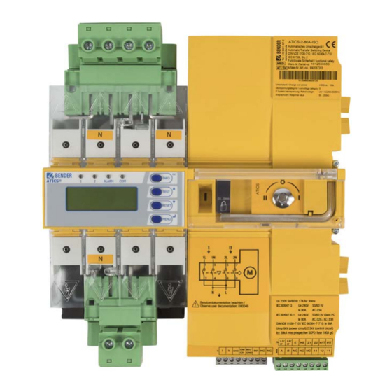
System description ATICS-2-ISO front view Legend Green plug connector for line 1 and line 2 Control buttons Inspection window for switch position Connection for ATICS-ES energy storage device (only for "-ES" version) / Connection for supply voltages (only for "-400" version) Manual mode of the device, indicates the switch position Allen key for manual mode Transparent cover for changeover switch (manual mode), sealable... -
Page 27: Mounting And Connection
ATICS-2-63A-ISO Mounting and connection of electrocution due to electric shock! Touching live parts of the system carries the risk of electric shock. Before installing the device and pri- or to working on the device connections, make sure that the power supply has been disconnected. -
Page 28: Removing Terminal Cover
Mounting and connection Required tools Use the following tools to connect the power unit and the control cables: • Torx® screwdriver T20 or 6.5 x 1.2 mm • Screwdriver 2.5 x 0.4 mm • Allen key 4 mm 4.1.2 Removing terminal cover 1. -
Page 29: Screw Mounting On Plate
ATICS-2-63A-ISO 4.1.4 Screw mounting on plate • Observe dimension diagram of rear view. • Use M5 mounting screws : Screw heads or washers reduce voltage clearances. Provide for sufficient clearance to live aution conductors (voltage clearance) by using mounting screws with flat screw heads and flat washers. If mounted on electrically conductive material: The mounting plate has to be earthed and the area un- der the terminals has to be covered with insulating material. - Page 30 Mounting and connection As a result, the choice of back-up fuses F should ensure both short-circuit protection for the transformer and the selectivity to overcurrent devices downstream of the IT systems. When choosing back-up fuses, observe both the maximum permissible values in accordance with the applicable local regulations and national and international standards to make sure that the contacts are weld-free.
-
Page 31: Connecting The Atics® Safely
ATICS-2-63A-ISO 4.2.2 Connecting the ATICS® safely of electrocution due to electric shock! If any of the supplies are switched on, some of the system parts which are not yet fully installed may be live. Preventing unintended switch-on: • Open the transparent cover •... - Page 32 GND, En/Ex Connection may only be used on ATICS-2-ISO-ES to connect ATICS-ES energy storage device. For all other variants, the connection is only intended for Bender-internal purposes (12 V). IN1/GND, IN1 Digital input, configurable (see chapter „Settings menu 6: Dig. input“ on p. 74)
-
Page 33: Atics® Basic Configuration
4.2.3 ATICS® basic configuration ! Risk of destruction if connected incorrectly. arning The terminals marked with "*" are intended for Bender-internal purposes only. If this is ignored, the ATICS® automatic transfer switching and monitoring device may be damaged. ATICS-2-ISO_D00046_04_M_XXEN / 03.2021... -
Page 34: Connection Example: Atics® With Bypass Switch
4.2.4 Connection example: ATICS® with bypass switch ! Risk of destruction if connected incorrectly. arning The terminals marked with "*" are intended for Bender-internal purposes only. If this is ignored, the ATICS® automatic transfer switching and monitoring device may be damaged. *An diese Klemmen ausschließlich ATICS-ES an Variante ATICS-2-ISO-xx-ES anschließen! -
Page 35: Connection Example: Atics® With Bypass Switch And Eds151
4.2.5 Connection example: ATICS® with bypass switch and EDS151 ! Risk of destruction if connected incorrectly. arning The terminals marked with "*" are intended for Bender-internal purposes only. If this is ignored, the ATICS® automatic transfer switching and monitoring device may be damaged. *An diese Klemmen ausschließlich ATICS-ES an Variante ATICS-2-ISO-xx-ES anschließen! -
Page 36: Connection Example: Atics® For 400-Volt Systems With N Conductor
4.2.6 Connection example: ATICS® for 400-volt systems with N conductor ! Risk of destruction if connected incorrectly. arning The terminals marked with "*" are intended for Bender-internal purposes only. If this is ignored, the ATICS® automatic transfer switching and monitoring device may be damaged. *An diese Klemmen ausschließlich ATICS-ES an Variante ATICS-2-ISO-xx-ES anschließen! - Page 37 ATICS-2-63A-ISO of ineffective voltage monitoring. The ATICS® must be supplied with power directly from the connected line (not from another phase) as shown. If this is not observed, the voltage monitoring does not function. ATICS-2-ISO_D00046_04_M_XXEN / 03.2021...
-
Page 38: Connection Example: Atics® For 400-Volt Systems Without N Conductor
Only use the T5+T6 autotransformers mentioned in the connection example. ! Risk of destruction if connected incorrectly. arning The terminals marked with "*" are intended for Bender-internal purposes only. If this is ignored, the ATICS® automatic transfer switching and monitoring device may be damaged. *An diese Klemmen ausschließlich A... - Page 39 ATICS-2-63A-ISO of ineffective voltage monitoring. The ATICS® must be supplied with power directly from the connected line (not from another phase) as shown. If this is not observed, the voltage monitoring does not function. ATICS-ES schließen! minals! ATICS-2-ISO_D00046_04_M_XXEN / 03.2021...
-
Page 40: Connection Example: Atics® With Atics-Es Energy Storage Device
! Risk of destruction if connected incorrectly. aution The terminals marked with "*" are intended for Bender-internal purposes only. If this is ignored, the ATICS® automatic transfer switching and monitoring device may be damaged. Power supply for the ATICS-ES energy storage device... - Page 41 ATICS-2-63A-ISO ATICS-2-ISO_D00046_04_M_XXEN / 03.2021...
-
Page 42: Instructions For Connection
DIN VDE 0100-710 (VDE 0100 Part 710) for transformers for medical IT systems. 4.2.9.2 Temperature sensors Bender IT system transformers are equipped with the temperature sensors required according to their insulation class. These temperature sensors (maximum of 6 sensors connected in series) are connected to terminals Z1 and Z2. -
Page 43: Bypass Switch (Optional)
ATICS-2-63A-ISO 4.2.9.7 Bypass switch (optional) The ATICS-BP-… bypass switch makes it possible to test and change the ATICS® transfer switching and monitoring device without interrupting the power supply to the line downstream of the transfer switching device. To make settings, refer to chapter „Operation with bypass switch“ on p. 90. -
Page 44: Manual Mode
Mounting and connection 4.3.2 Manual mode of injury from rotating Allen key. When the transparent cover is closed, the ATICS® is in automatic mode. The ATICS® detects this by the button being pressed under the transparent cover. When the transparent cover is opened, the button is no longer pressed and the ATICS®... -
Page 45: Commissioning, Settings And Testing
ATICS-2-63A-ISO Commissioning, settings and testing Design and Installation of missing or incorrect displays on MK..., TM..., FTC… or CP9xx! MK… alarm indicator and test combinations, TM... alarm indicator and operator panels or BMS- Ethernet gateways COM460…, which, together with an ATICS®, are connected to a BMS bus must be provided with the latest operating software (e.g. -
Page 46: Atics® Messages On The Bms Bus (Channel Use)
Commissioning, settings and testing This is achieved by entering the ATICS® device address in the alarm address table. If necessary, individu- al messages can also be programmed for channels 1, 2, 5, 7…11. No individual text may be pro- grammed for channel 6! The failure of the other MK…... - Page 47 ATICS-2-63A-ISO Entry in the menu Description Operating Alarm mes- Error chan- 1. Alarm/meas.values message sage 11. Temperature Transformer tem- Temperature perature 12. Fault location: -- EDS control (EDS start) * Message dependent on the parameter assignment in the „Settings menu 1: Changeover“ on p. 67 -> "System"...
-
Page 48: Tests, Decommissioning
Commissioning, settings and testing 5.1.3 Tests, decommissioning • Abide by the relevant local or national regulations for periodic verification on electrical instal- lations. • If you notice changes on the ATICS®, you must immediately start checking the transfer switch- ing device. Observe the alarms on the transfer switching device. -
Page 49: Addressing Examples
ATICS-2-63A-ISO Addressing examples Use terminating resistors correctly Communication via the BMS bus is only guaranteed when there is a terminating resistor at the be- ginning and at the end of the BMS bus. Other terminating resistors cause malfunction and must not be used. - Page 50 Commissioning, settings and testing Two automatic transfer switching devices • One with an insulation fault locator • With one alarm indicator and test combination in each case • And central monitoring Device Parameter Address settings ATICS® Bus address for area A First MK…...
-
Page 51: Operation
ATICS-2-63A-ISO Operation Operating and display elements ALARM LED/Button Description LED "1" lights up: Line 1 is ready LED "2" lights up: Line 2 is ready LED "ALARM" lights up: Alarm present LED "COM" flashes: Communication via BMS bus "INFO" Query standard information "ESC"... -
Page 52: Display During Fault Condition
Operation 228 V 0 . 00 V 6.2.2 Display during fault condition 50 . 0Hz 50 . 0Hz There is an alarm message. 12 : 23 160kΩ 228 V 0 . 00 V • The yellow "Alarm" LED lights up. Unterspannung / Undervoltage 50 . - Page 53 ATICS-2-63A-ISO Menu item Function Page 1. IT system Test of the integrated insulation monitoring device (insulation resistance, P. 54 load in %, overtemperature) 2. Autom. changeover Test of the changeover function. Switches back automatically after time P. 54 t(test). 3. Manual changeover Test of the changeover function.
-
Page 54: Test Menu 1: It System
Operation 6.2.3.1 Test menu 1: IT system IT system IT system Cancel IT system Tests the integrated insulation monitoring device (insulation resistance, load in %, overtemperature). The progress of the test is shown on the display. Cancel Return to test menu Press the "ESC"... -
Page 55: Test Menu 3: Manual Changeover
ATICS-2-63A-ISO 6.2.3.3 Test menu 3: Manual changeover Manual changeover Manual changeover Cancel Manual changeover Test of the changeover function. The device switches to the redundant line and remains in this switch position. The changeover period t(1->2) is displayed. The device does not switch back to the preferred line until the "RESET"... -
Page 56: Checking The Atics-Es Energy Storage Device (If Available)
Operation Save Save Cancel 1. Save Saves the date of last changeover as test date, as long as that date is later than the previous entry. 2. Cancel Return to test menu "Last switch" After saving, the date on which the next test is due is increased by the test interval (in this case, 6 months). -
Page 57: Test Menu 6: Test Communication
ATICS-2-63A-ISO Test t (1->2): 110ms t (Test): Quit RESET The display shows the test duration. that the generator test is accidentally not completed. If the test menu 5: "Generator" is left after the generator has started, then ATICS® remains in this switch position and in "TEST"... -
Page 58: Reset Function
Operation 6.2.4 Reset function A RESET is used to reset the alarm and fault messages for the device as well as to disable the switch- back lock of the changeover function. There are several ways to call up the reset menu: •... -
Page 59: Reset Menu 2: Switchbacklock
ATICS-2-63A-ISO 6.2.4.2 Reset menu 2: SwitchBackLock Delete Delete Cancel Delete Disable the switch-back lock of the changeover function. The progress of the test is shown on the display. The device switches back to the redundant line. Cancel Return to reset menu There are different possibilities to disable the switch-back lock via gateway (COM4xx, CP700 etc.):... -
Page 60: Reset Menu 4: Service Alarm
Operation Menu Description Exit Exit "Changeover" reset menu; go up one menu level Changeover: xxx Number of changeovers performed 2. Alarm: 8000 Alarm value for maximum number of changeovers performed* Delete Increase alarm value by 500 changeovers Operat. time: xxh Operating hours counter (h=hours, d=days, mo=months) 5. -
Page 61: Menu Mode: Operation And Setting
ATICS-2-63A-ISO Menu mode: Operation and setting Switching on and calling up the main menu When the device is connected to the power supply, the follow- ing information appears on the display for approx. 3 seconds: If the device has been without power for several days, time and date must be readjusted. -
Page 62: Menu Overview Diagram
Menu mode: Operation and setting Menu overview diagram The following diagram will help you to navigate through the menus: Exit Exit 1.History 1.Alarm/meas.values 2.Data logger 3.Config. logger 2.Changeover 4.Test data logger 3.History/Logger 5.Service logger Exit 1.Changeover 2.Voltage 3.Current 4.IT system 5.Relay 6.Digital Input 4.Settings... -
Page 63: Function Of The Main Menu
ATICS-2-63A-ISO Function of the main menu Menu item Function Page Exit Exit menu mode 1. Alarm/meas.values Display saved status messages, alarm messages and measured values P. 63 2. Changeover Display information on the changeover function (number, test) P. 64 3. History/Loggers Display history memory, data logger, configuration logger, test logger and P. -
Page 64: Menu 2: Changeover
Menu mode: Operation and setting Menu Description Line 1: Measured value frequency Line 1: 50.0Hz Line 2: Measured value frequency Line 2: 50.0Hz Changeover period t(1->2) of the last test t(1->2): 356ms Next TEST by (date) TEST: 02.07.19 Next service by (date) Service: 11.07.19 The following different channel assignment applies to the "Test"... -
Page 65: Menu 3: History/Loggers
ATICS-2-63A-ISO Menu Description Date for next test (changeover) TEST: dd.mm.yy Date for next service Service: dd.mm.yy Date of the last test (TEST) or last changeover (LAST SWITCH). TEST: dd.mm.yy 7.3.3 Menu 3: History/Loggers The device saves the history of alarm messages, measured values, settings, tests and service measures in different memories (logger). -
Page 66: Operating Examples: History
(in this case: [4/1]). Channel 1 means that the first digital input has been changed. Please contact the Bender service and provide the identification number if the modification led to an undesirable behaviour of the device. 7.3.4 Menu 4: Settings The settings menus are protected by a password (see chapter „Settings menu 11: Password“... -
Page 67: Settings Menu 1: Changeover
The device has two separate passwords for the "Settings" menu and the "TEST" menu. Adjustable in each case: change password, enable/disable password 12. Service Only intended for settings by authorised Bender service personnel. P. 80 Call up information about the device status and make settings for specific operat- ing conditions. - Page 68 Menu mode: Operation and setting Menu item Function 3. t(2->1) Return transfer delay time to the preferred line: Setting range: 0 s…180 min Resolution of settings: 50 ms / 100 ms / 1 s / 5 s / 1 min 4.
-
Page 69: Settings Menu 2: Voltage
ATICS-2-63A-ISO Menu item Function 9. Reminder Prewarning time for test interval (set value smaller than test interval): Setting range: off, 1…60 days Resolution of setting: 1 day 10. Serviceinterv. Service interval: Setting range: off, 6…48 months Resolution of setting: 6 months 11. -
Page 70: Settings Menu 3: Current
Menu mode: Operation and setting Selecting a line: 1. Use the " " arrow button to go to the line setting. Press the " " button. 2. Use the arrow buttons to select one line (voltage 1, 2) or both lines (voltage 1…2). Press the " "... -
Page 71: Settings Menu 4: It System
Exit settings menu "Current"; go up one menu level 1. Mode Current monitoring enabled No current monitoring 2. transformer STW3 Bender measuring current transformer STW3 STW4 Bender measuring current transformer STW4 3. CT monitoring. CT connection monitoring enabled CT connection monitoring disabled Note: External interference from loads can cause false tripping. -
Page 72: Settings Menu 5: Relay
Menu mode: Operation and setting Menu Description 7. t(off) Delay on release load: Setting range: 0 s…100 s Resolution of setting: 1 s 8. Temperature Temperature monitoring enabled Temperature monitoring disabled 9. Fault location Insulation fault location disabled auto Insulation fault location enabled Note: This function is only available if a suitable master is connected via the BMS bus (e.g. - Page 73 ATICS-2-63A-ISO Adjusting the settings: Menu Description Exit Exit settings menu "Relay"; go up one menu level 1. Function ALARM Relay switches if at least one of the following menus 3…12 is set to "on" and the corresponding alarm message appears.
-
Page 74: Settings Menu 6: Dig. Input
Menu mode: Operation and setting Menu Description 12. Temperature Relay switches in the event of overtemperature in the IT system transformer 13. Undervolt. Relay switches in the event of undervoltage at the ATICS® output (line 3) The reminders for the test (7. Test interval) or the service (8. Serviceinterv) are always triggered at 12:00 pm. - Page 75 ATICS-2-63A-ISO Menu Description Exit Exit settings menu "Voltage"; go up one menu level : A parameter change can result in an immediate changeover. 1. Functions Digital input disabled Manual/Automatic. Manual mode means that automatic changeover can no longer take place.
-
Page 76: Settings Menu 7: Data Loggers
Menu mode: Operation and setting You can adjust the settings for six data loggers of the device in this menu. These data loggers (see chapter „Menu 3: History/Loggers“ on p. 65) display the history of measured values: Voltage line 1 Voltage line 2 Switch position of the transfer switching device Load current I(3) in the TN system downstream of the transfer switching device... -
Page 77: Settings Menu 8: Language
ATICS-2-63A-ISO Menu Description Exit Exit settings menu "Datalogger"; go up one menu level 1. Modific. Once the measured value has been changed by the set % value, a new measured value is stored in the data logger. Setting range: 0 … 100 % Resolution of setting: 1 % 2. -
Page 78: Settings Menu 9: Interface
Menu mode: Operation and setting Set the device address for the connection to the internal BMS bus. Change the device address con- cerned when several devices are connected to one BMS bus. One device (e.g. MK800) must have ad- dress 1 (master). All other devices are addressed in consecutive order: 2,3,4…. There should be no gaps between the addresses. -
Page 79: Settings Menu 11: Password
ATICS-2-63A-ISO Menu Description Exit Exit settings menu "Clock"; go up one menu level 1. Format d.m.y German format (day.month.year) m-d-y American format 2. Date Setting the date (e.g. dd.mm.yyyy) 3. Time Setting the time (hours and minutes) 7.3.4.11 Settings menu 11: Password The device has two separate passwords for the "Settings"... -
Page 80: Settings Menu 12: Service
The service menu is intended for settings by authorised Bender service personnel. It is only accessible to the Bender service. In the service menu, information about the device status can be called up and settings for specific operating conditions can be made. -
Page 81: Menu 6: Dig. Input
Address set on the BMS bus Address: 3 Line 4: Serial number of the device No.: 1234567890 Line 5…8: Software versions of the four controllers of the device … Bender address, website … Exit. Exit standard information. ATICS-2-ISO_D00046_04_M_XXEN / 03.2021... - Page 82 Troubleshooting ATICS-2-ISO_D00046_04_M_XXEN / 03.2021...
-
Page 83: Troubleshooting
ATICS-2-63A-ISO Troubleshooting Fault and alarm messages In the event of an alarm, the messages of the ATICS® transfer switching and monitoring device will ena- ble you to narrow down the possible causes. Some messages may point to several causes. The follow- ing possible faults are indicated by messages on the ATICS®... - Page 84 (see chapter „Settings menu 9: Inter- face“ on p. 77) must be disabled. Service by __ Reminder for next service • Schedule appointment with the Bender service. (date) Functional test Reminder for next test • Schedule appointment for next test.
-
Page 85: Messages With Error Code Or Service Code
Error code/service Description Action code 1.xx, 4.xx, 9.xx Fault message from the internal memory • Contact the Bender service. monitoring. 3.10 Prewarning • For functional safety SIL 2 require- ments according to IEC 61508-2, The max. number of operating hours will be the replacement must be planned. - Page 86 Troubleshooting Error code/service Description Action code 8.21 … 8.30 ISOMETER® or transformer monitoring error. • Reset, then execute test of the IT system • Check that the current firmware is installed. • When no fault is displayed: OK. Otherwise replace the device. •...
-
Page 87: Frequently Asked Questions
3. Have the article and serial number of the device at hand. 4. Contact the Bender service and state the type of error and the three-digit error code. Frequently asked questions A series of clicks is always heard at around noon. What does that mean? ATICS®... - Page 88 Why does writing back reports/backups lead to error messages? ATICS® – like many Bender devices – can be monitored and configured by means of a Bender gateway CP700, COM46x… etc. The gateways are operated via a web user interface that is displayed using an Internet browser.
-
Page 89: Periodic Verification And Service
Periodic verification and service Periodic verification The use of Bender products ensures protective measures against certain hazards when operating elec- trical systems. The corresponding legal requirements are defined in the Ordinance on Industrial Safety and Health (BetrSichV) and the supplementary Technical Rules (TRBS): Every company is obliged to draw up a risk assessment for its work equipment (electrical systems and equipment). -
Page 90: Maintenance
Periodic verification and service Action To be per- Interval formed by Services for the periodic verification of Bender products in electrical Bender Every twelve installations: service or months* • For checking the effectiveness of the protective measures monitored by electrically... -
Page 91: Replacing The Atics
ATICS-2-63A-ISO of short circuit if "Enable bypass" light is ignored. If ATICS® is not connected to the line to which the bypass switch is connected, a short circuit may oc- cur between line 1 and line 2. The bypass switch may only be operated when the green "Enable Bypass"... -
Page 92: Removing The Existing Atics
Periodic verification and service 9.5.1 Removing the existing ATICS® 1. Record settings on the existing ATICS®. The settings should match the entries in the checklist (see checklist, included in the scope of delivery). 2. Disconnect the device from the power supply or switch on the bypass switch. Switch existing ATICS®... - Page 93 ATICS-2-63A-ISO Removing the ATICS® in case of DIN rail mounting Undo screws (D). N N N Remove lower and upper terminal covers (A) by using a screw- driver to push back the locking hook (B) located approximately in the middle of the cover in each case.
-
Page 94: Installing A New Atics
Periodic verification and service Removing the ATICS® in case of screw mounting Remove lower and upper terminal covers (A) by using a N N N screwdriver to push back the locking hook (B) located ap- proximately in the middle of the cover in each case. Undo the Allen screws of the terminals (C). -
Page 95: Technical Data
ATICS-2-63A-ISO Technical data 10.1 Tabular data Insulation coordination acc. to IEC 60664-1/IEC 60664-3 Overvoltage category ��������������������������������������������������������������������������������������������������������������������������������������������������������������������������������� III Pollution degree outside, inside ������������������������������������������������������������������������������������������������������������������������������������������������������������������ 2 Rated insulation voltage� ���������������������������������������������������������������������������������������������������������������������������������������������������������������������� 250 V Protective separation between ������������������������������������������������������������������������������������������������������������Line 1 – Line 2; Line 1, 2, 3 – RS-485 ��������������������������������������������������������������������������������������������������������������������������������... - Page 96 Technical data IT system monitoring Insulation monitoring Nominal system voltage (operating range)���� ������������������ ���������������������������������������������������������������������������������������������������������� 80…275 V Measuring range��������������������������������������������� ������������������������������������������������������������������������������������������������������������������������ 10 kΩ…1 MΩ Measurement method���������������������������������������� ����������������������������������������������������������������������������������������AMP (adaptive measuring pulse) Response value R (ALARM 1)�������������� ��������������������������� ���������������������������������������������������������������������������������������������������������50…250 kΩ Relative uncertainty ����������������������������� ���������������������������� ����������������������������������������������������������������������������������������������������������������� ±15 % Hysteresis �������������������������������������������������...
- Page 97 ATICS-2-63A-ISO Displays and data memory Display: graphic display�� ���������������������������������������������������������������������������������������������������������������������������������������� languages DE, EN, FR, PL Alarm LEDs � ��������������������������������������������������������������������������������������������������������������������������������������������������������� Line 1, Line 2, Alarm, Com History memory�� �����������������������������������������������������������������������������������������������������������������������������������������������������������������500 data records Data logger������ ����������������������������������������������������������������������������������������������������������������������������������������������������� 500 data records/channel Config� logger��� �������������������������������������������������������������������������������������������������������������������������������������������������������������������300 data records Test logger��������...
- Page 98 Technical data Terminals Power section Connection directly to ATICS®, for plug connections����������������������������������������������������������������������� screw-type terminals rigid (flexible)/conductor sizes �������������������������������� �������������������������������������������������������������� 10…70 mm² (6…50 mm²)/8 (10)…0 AWG Stripping length������������������� ���������������������� ���������������������������������������������������������������������������������������������������������������������������������������� 15 mm Tightening torque (hexagon socket 4 mm) ���� �������������������������������������������������������������������������������������������������������������������������������������� 5 Nm Connection type�����...
- Page 99 ATICS-2-63A-ISO Short-circuit currents ATICS-2- ATICS-2- 63A-ISO... 80A-ISO... Thermal current Ith (40 °C) 63 A 80 A Current rated as conditional short circuit with gG fuses according to DIN Conditional short-circuit current I (kA eff.) Associated fuse rating (A gG) Current rated as conditional short circuit with circuit breaker that ensures tripping in less than 0.3 s...
-
Page 100: Tüv Test Report According To Vde 0100 Part 710
Technical data 10.2 TÜV test report according to VDE 0100 Part 710 ATICS-2-ISO_D00046_04_M_XXEN / 03.2021... -
Page 101: Tüv Certificate Regarding Functional Safety
ATICS-2-63A-ISO 10.3 TÜV certificate regarding functional safety ATICS-2-ISO_D00046_04_M_XXEN / 03.2021... -
Page 102: Standards And Certifications
The standards marked with * were part of the test conducted by TÜV Süd. 10.5 Ordering information Type Nominal voltage U Rated operational current I Art. No. Manual No. ATICS-2-63A-ISO AC 240 V AC 63 A B92057202 D00046 ATICS-2-63A-ISO-ES* AC 240 V... -
Page 103: Additional Documents
• ATICS-BP-SET (bypass switch set for ATICS®) • STW2, STW3, STW4 measuring current transformers • BMS bus Bender measuring device interface • COM465… BMS-Ethernet gateway for the connection of the Bender measuring device inter- face to TCP/IP networks • EDS150 insulation fault locator •... -
Page 104: Document Revision History
Nachdruck und Vervielfältigung Reprinting and duplicating nur mit Genehmigung des Herausgebers. only with permission of the publisher. Bender GmbH & Co. KG Bender GmbH & Co. KG Postfach 1161 • 35301 Grünberg • Deutschland PO Box 1161 • 35301 Grünberg • Germany Londorfer Str.
Need help?
Do you have a question about the ATICS-2-63A-ISO and is the answer not in the manual?
Questions and answers