Daikin VRV IV S Series Engineering Data
50 hz
Hide thumbs
Also See for VRV IV S Series:
- Installation manual (23 pages) ,
- Service manual (272 pages) ,
- Installer and user manual (56 pages)
Table of Contents
Advertisement
Advertisement
Chapters
Table of Contents

Related Manuals for Daikin VRV IV S Series


Summary of Contents for Daikin VRV IV S Series
- Page 1 EDMT331529A RXYMQ4-6AVE RXYMQ8/9AY1 Heat Pump 50 Hz...
-
Page 3: Table Of Contents
EDMT331529A Introduction ......................... 2 Part 1 General Information ................3 Part 2 Indoor Units....................23 FXFQ-S Ceiling Mounted Cassette (Round Flow with Sensing) Type....25 FXFQ-LU Ceiling Mounted Cassette (Round Flow) Type ........43 Ceiling Mounted Cassette (Compact Multi Flow) Type... FXZQ-M ....61 FXUQ-A... -
Page 4: Introduction
Introduction EDMT331529A 1. Introduction Publication List of Engineering Data for VRV Products Published Refrigerant Type Product Series Book No. Type, Hz Model name Area Note High-COP type Argentina, (Energy Saving Type) Chile, RXYQ12-50THY1(E) Uruguay - Revision for and other EU Biocidal EDMT341421A H/P 50 Hz Standard type... -
Page 5: Part 1 General Information
EDMT331529A Part 1 General Information 1. Model Names of Indoor/Outdoor Units............4 1.1 Indoor Units ....................4 1.2 Outdoor Units ...................5 1.3 Air Treatment Equipment .................5 2. External Appearance................6 2.1 Indoor Units ....................6 2.2 Outdoor Units ...................8 2.3 Air Treatment Equipment .................8 3. -
Page 6: Part 2 Indoor Units
Model Names of Indoor/Outdoor Units EDMT331529A 1. Model Names of Indoor/Outdoor Units Indoor Units VRV Indoor Units 2.2kW 2.8kW 3.6kW 4.5kW 5.6kW 7.1kW 8.0kW 9.0kW 11.2kW 14.0kW 16.0kW 22.4kW 28.0kW Power Capacity range 0.8HP 1.25HP 1.6HP 2.5HP 3.2HP 10HP supply, Standard Capacity index 31.25... -
Page 7: Outdoor Units
EDMT331529A Model Names of Indoor/Outdoor Units Residential Indoor Units with Connection to BP Units Heat Pump Capacity range 2.0kW 2.5kW 3.5kW 5.0kW 6.0kW 7.1kW Power supply, Capacity index Standard CDXS — 25EA 35EA — — — Slim Ceiling Mounted Duct Type FDXS —... -
Page 8: Ceiling Mounted Cassette (Round Flow With Sensing) Type
External Appearance EDMT331529A 2. External Appearance Indoor Units VRV Indoor Units Ceiling mounted cassette (Round flow with sensing) type Ceiling mounted duct type FXFQ-S FXMQ-P Ceiling mounted cassette (Round flow) type Ceiling mounted duct type FXFQ-LU FXMQ-MA Ceiling mounted cassette (Compact multi flow) type Ceiling suspended type FXZQ-M FXHQ-MA... - Page 9 EDMT331529A External Appearance Residential Indoor Units with Connection to BP Units Slim ceiling mounted duct type Wall mounted type (700 mm width type) FTXS-D CDXS-EA FTXS-E Slim ceiling mounted duct type Wall mounted type (900/1,100 mm width type) FTXS-F FDXS-C Wall mounted type FTXJ-N BP Units...
-
Page 10: Outdoor Units
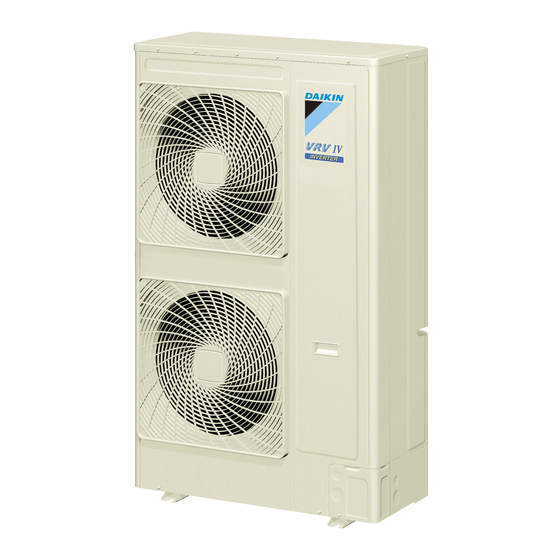
External Appearance EDMT331529A Outdoor Units RXYMQ4/5AVE RXYMQ6AVE RXYMQ8/9AY1 Air Treatment Equipment Heat reclaim ventilator (VAM series) VAM-GJ General Information... -
Page 11: Nomenclature
EDMT331529A Nomenclature 3. Nomenclature VRV Indoor Unit Power supply symbol VE: 1 phase, 220-240/220V, 50/60Hz V1 : 1 phase, 220-240V, 50Hz VM: 1 phase, 220-240/220-230V, 50/60Hz Y1: 3 phase, 380-415V, 50Hz Indicates major design category Capacity indication Conversion to kW (Horsepower) 25: 2.8 kW (1 HP) 125: 14.0 kW (5 HP) 250: 28.0 kW (10 HP) - Page 12 Nomenclature EDMT331529A Residential Indoor Unit (SPLIT) Front panel colour symbol Suffixed when the model has colour variations W: White S: Silver Standard symbol A: Australia Power supply symbol VM: 1 phase, 220-240/220-230V, 50/60 Hz V1: 1 phase, 220-240V, 50 Hz Model change symbol Progress with each design change Capacity indication...
- Page 13 EDMT331529A Nomenclature Outdoor Unit Power supply symbol VE: 1 phase, 220-230/220V, 50/60Hz Y1: 3 phase, 380-415V, 50Hz Indicates major design category Capacity indication Conversion to kW (Horsepower) 4: 11.2 kW (4 HP) 6: 16.0 kW (6 HP) 9: 24.0 kW (9 HP) Refrigerant Q: R410A Shape...
-
Page 14: Capacity Range
Capacity Range EDMT331529A 4. Capacity Range Capacity Range for VRV Indoor Units Only 4.1.1 Combination Ratio Total capacity index of the indoor units Combination ratio = Capacity index of the outdoor units Max. combination ratio Type Min. combination ratio Types of connected indoor units VRV indoor units Single outdoor units 130%... -
Page 15: Capacity Range For Mixed Combination Of Vrv And Residential Indoor Units
EDMT331529A Capacity Range Capacity Range for Mixed Combination of VRV and Residential Indoor Units 4.2.1 Combination Ratio Total capacity index of the indoor units Combination ratio = Capacity index of the outdoor units Max. combination ratio Type Min. combination ratio Type of connected indoor units VRV and Residential indoor units *1 Single outdoor units... -
Page 16: Selection Procedure
Selection Procedure EDMT331529A 5. Selection Procedure Selection Procedure for VRV Indoor Units Only 5.1.1 Flowchart Given Conditions: · Design temperature and humidity (indoor & outdoor) [1] ] Given conditions · Required heat load of each room · System peak load ( if necessary) ·... - Page 17 EDMT331529A Selection Procedure Equivalent pipe length 30m Level difference Select VRV indoor units FXMQ-P series for each room. -Safety factor In this example, safety factor is not used. (i. e., safety factor = 1.0) [2] Selection of indoor units Calculate total heat capacity of indoor units corrected for indoor air temperature. In case design temperature of the indoor air falls between temperatures listed in the table, calculate the capacity by interpolation.
- Page 18 Selection Procedure EDMT331529A [3] –2 Provisionally select outdoor unit (1) Calculate CI (Capacity Index) of the selected indoor units. CI of VRV indoor units VRV Indoor Units CI of FXMQ20PVE = 20 2.2kW 2.8kW 3.6kW 4.5kW 5.6kW 7.1kW 8.0kW 9.0kW 11.2kW 14.0kW 16.0kW 22.4kW 28.0kW Power Capacity range CI of FXMQ32PVE = 31.25...
- Page 19 EDMT331529A Selection Procedure -Confirm capacity correction factor by piping length and level difference (K1) (K1) = 0.95 0.95 -Calculate capacity correction factor by piping heat loss (K2) (K2) = 1 + (heat loss factor per meter of piping × (equivalent piping length – 7.5m)) / 100 In cooling mode, heat loss factor per meter at 33°C is calculated as below.
-
Page 20: Selection Procedure For Mixed Selection Of Vrv And Residential Indoor Units
Selection Procedure EDMT331529A Selection Procedure for Mixed Selection of VRV and Residential Indoor Units 5.2.1 Flowchart For the selection of residential indoor units, the following procedures shall be added to the standard selection of VRV indoor units. -Correct the capacity of VRV indoor units for “Evaporating temperature (Te: 9ºC)”. (only for cooling capacity) -Correct the capacity of Residential indoor units for “Indoor air temperature”. - Page 21 EDMT331529A Selection Procedure -Correction factors in case Te: 9ºC FXDQ-PB, -NB VRV (Te: 9˚C) 14˚CWB 16˚CWB 18˚CWB 19˚CWB 20˚CWB 22˚CWB 24˚CWB 20˚CDB 23˚CDB 26˚CDB 27˚CDB 28˚CDB 30˚CDB 32˚CDB 0.685 0.694 0.755 0.778 0.802 0.833 0.855 FXDQ20PBVE FXDQ20PBVET 1.124 1.176 1.118 1.094 1.074 1.053...
- Page 22 Selection Procedure EDMT331529A [3] –2 Provisionally select outdoor unit (1) Calculate CI (Capacity Index) of the selected indoor units. CI of VRV indoor units VRV Indoor Units 2.2kW 2.8kW 3.6kW 4.5kW 5.6kW 7.1kW 8.0kW 9.0kW 11.2kW 14.0kW 16.0kW 22.4kW 28.0kW CI of FXDQ20PBVE = 20 Power Capacity range...
- Page 23 EDMT331529A Selection Procedure [3] –3 Calculate the corrected capacity of the outdoor unit. Using the capacity table of the outdoor unit, calculate the capacity (B) corrected for “Outdoor air temperature”, “Indoor air temperature”, “Combination ratio”, and “Correction factor for outdoor units”. RXYMQ8AY1 Cooling capacity (Capacity correction factor: 0.95) (Te: 9ºC) RXYMQ8AY1 Cooling capacity (Capacity correction factor: 0.90) (Te: 9ºC) -Calculate the capacity in case combination ratio = 104%...
- Page 24 Selection Procedure EDMT331529A -Confirm capacity correction factor for piping length and level difference (K1) (K1) = 0.95 0.95 -Calculate capacity correction factor for piping heat loss (K2) (K2) = 1 + (heat loss factor per meter of piping × (equivalent piping length – 7.5m)) / 100 Heat loss factor per meter at 33ºC is calculated as below.
-
Page 25: Fxfq-S
EDMT331529A Part 2 Indoor Units FXFQ-S Ceiling Mounted Cassette (Round Flow with Sensing) Type ... . . 25 FXFQ-LU Ceiling Mounted Cassette (Round Flow) Type ......43 FXZQ-M Ceiling Mounted Cassette (Compact Multi Flow) Type . - Page 26 EDMT331529A FXLQ-MA / FXNQ-MA Floor Standing Type / Concealed Floor Standing Type ... . . 243 FXVQ-N Floor Standing Duct Type ....269 Indoor Units...
- Page 27 EDMT331529A FXFQ-S Ceiling Mounted Cassette (Round Flow with Sensing) Type 1. Specifications ..................26 2. Dimensions ...................28 3. Piping Diagrams..................31 4. Wiring Diagrams..................32 5. Electric Characteristics................33 6. Safety Devices Setting ................34 7. Capacity Tables ..................35 7.1 Cooling Capacity ..................35 7.2 Heating Capacity ..................35 7.3 Correction Factor for Te: 9°C ..............36 8.
-
Page 28: Specifications
Specifications EDMT331529A 1. Specifications Ceiling mounted cassette (Round flow with sensing) type Model FXFQ25SVM FXFQ32SVM FXFQ40SVM FXFQ50SVM 1 phase, 1 phase, 1 phase, 1 phase, Power supply 220-240/220 · 230V, 220-240/220 · 230V, 220-240/220 · 230V, 220-240/220 · 230V, 50/60Hz 50/60Hz 50/60Hz 50/60Hz... - Page 29 EDMT331529A Specifications Ceiling mounted cassette (Round flow with sensing) type Model FXFQ63SVM FXFQ80SVM FXFQ100SVM FXFQ125SVM 1 phase, 1 phase, 1 phase, 1 phase, Power supply 220-240/220 · 230V, 220-240/220 · 230V, 220-240/220 · 230V, 220-240/220 · 230V, 50/60Hz 50/60Hz 50/60Hz 50/60Hz kcal/h 6,100...
-
Page 30: Dimensions
Dimensions EDMT331529A 2. Dimensions FXFQ25SVM / FXFQ32SVM / FXFQ40SVM / FXFQ50SVM Unit (mm) FXFQ-S... - Page 31 EDMT331529A Dimensions FXFQ63SVM / FXFQ80SVM Unit (mm) FXFQ-S...
- Page 32 Dimensions EDMT331529A FXFQ100SVM / FXFQ125SVM Unit (mm) FXFQ-S...
-
Page 33: Piping Diagrams
EDMT331529A Piping Diagrams 3. Piping Diagrams FXFQ25SVM / FXFQ32SVM / FXFQ40SVM / FXFQ50SVM / FXFQ63SVM / FXFQ80SVM / FXFQ100SVM / FXFQ125SVM 4D024460M Refrigerant pipe connection port diameters (mm) Model Liquid φ12.7 φ6.4 FXFQ25SVM / FXFQ32SVM / FXFQ40SVM / FXFQ50SVM φ15.9 φ9.5 FXFQ63SVM / FXFQ80SVM / FXFQ100SVM / FXFQ125SVM... -
Page 34: Wiring Diagrams
Wiring Diagrams EDMT331529A 4. Wiring Diagrams FXFQ25SVM / FXFQ32SVM / FXFQ40SVM / FXFQ50SVM / FXFQ63SVM / FXFQ80SVM / FXFQ100SVM / FXFQ125SVM FXFQ-S... -
Page 35: Electric Characteristics
EDMT331529A Electric Characteristics 5. Electric Characteristics FXFQ25SVM / FXFQ32SVM / FXFQ40SVM / FXFQ50SVM / FXFQ63SVM / FXFQ80SVM / FXFQ100SVM / FXFQ125SVM 4D084422 FXFQ-S... -
Page 36: Safety Devices Setting
Safety Devices Setting EDMT331529A 6. Safety Devices Setting Model FXFQ25SVM FXFQ32SVM FXFQ40SVM FXFQ50SVM FXFQ63SVM FXFQ80SVM FXFQ100SVM FXFQ125SVM Printed circuit board fuse 250V 3.15A 250V 3.15A 250V 3.15A 250V 3.15A 250V 3.15A 250V 3.15A 250V 3.15A 250V 3.15A Drain pump thermal °C –... -
Page 37: Capacity Tables
EDMT331529A Capacity Tables 7. Capacity Tables Cooling Capacity Indoor air temp. 14.0°CWB 16.0°CWB 18.0°CWB 19.0°CWB 20.0°CWB 22.0°CWB 24.0°CWB Capacity Model indication 20°CDB 23°CDB 26°CDB 27°CDB 28°CDB 30°CDB 32°CDB FXFQ25SVM FXFQ32SVM FXFQ40SVM FXFQ50SVM FXFQ63SVM FXFQ80SVM FXFQ100SVM 10.5 11.2 11.3 11.6 11.9 FXFQ125SVM 11.3 13.1... -
Page 38: Correction Factor For Te: 9°C
Capacity Tables EDMT331529A Correction Factor for Te: 9°C When a mixed combination of VRV and residential indoor units is connected VRV (Te: 9°C) 14°CWB 16°CWB 18°CWB 19°CWB 20°CWB 22°CWB 24°CWB 20°CDB 23°CDB 26°CDB 27°CDB 28°CDB 30°CDB 32°CDB 0.724 0.757 0.808 0.827 0.844 0.873... -
Page 39: Sound Levels
EDMT331529A Sound Levels 8. Sound Levels FXFQ25SVM / FXFQ32SVM FXFQ40SVM FXFQ-S... - Page 40 Sound Levels EDMT331529A FXFQ50SVM FXFQ63SVM FXFQ-S...
- Page 41 EDMT331529A Sound Levels FXFQ80SVM FXFQ100SVM FXFQ-S...
- Page 42 Sound Levels EDMT331529A FXFQ125SVM FXFQ-S...
-
Page 43: Centre Of Gravity
EDMT331529A Centre of Gravity 9. Centre of Gravity FXFQ25SVM / FXFQ32SVM / FXFQ40SVM / FXFQ50SVM / FXFQ63SVM / FXFQ80SVM / FXFQ100SVM / FXFQ125SVM Unit (mm) 4D052237Q FXFQ-S... -
Page 44: Accessories
Accessories EDMT331529A 10. Accessories 10.1 Optional Accessories (for Unit) Model Item Note FXFQ25SVM FXFQ32SVM FXFQ40SVM FXFQ50SVM FXFQ63SVM FXFQ80SVM FXFQ100SVM FXFQ125SVM Decoration panel BYCQ125B-W1 Sealing member of air discharge KDBHQ55B140 outlet Panel spacer KDBP55H160FA High KAFP556B80 KAFP556B160 efficiency KAFP557B80 KAFP557B160 filter unit Replacement KAFP552B80 KAFP552B160... -
Page 45: Ceiling Mounted Cassette (Round Flow) Type
EDMT331529A FXFQ-LU Ceiling Mounted Cassette (Round Flow) Type 1. Specifications ..................44 2. Dimensions ...................46 3. Piping Diagrams..................49 4. Wiring Diagrams..................50 5. Electric Characteristics................51 6. Safety Devices Setting ................52 7. Capacity Tables ..................53 7.1 Cooling Capacity ..................53 7.2 Heating Capacity ..................53 7.3 Correction Factor for Te: 9°C ..............54 8. -
Page 46: Specifications
Specifications EDMT331529A 1. Specifications Ceiling mounted cassette (Round flow) type Model FXFQ25LUV1 FXFQ32LUV1 FXFQ40LUV1 FXFQ50LUV1 Power supply 1 phase, 220-240V, 50Hz 1 phase, 220-240V, 50Hz 1 phase, 220-240V, 50Hz 1 phase, 220-240V, 50Hz kcal/h 2,400 3,100 3,900 4,800 1 3 Cooling capacity Btu/h 9,600 12,300... - Page 47 EDMT331529A Specifications Ceiling mounted cassette (Round flow) type Model FXFQ63LUV1 FXFQ80LUV1 FXFQ100LUV1 FXFQ125LUV1 Power supply 1 phase, 220-240V, 50Hz 1 phase, 220-240V, 50Hz 1 phase, 220-240V, 50Hz 1 phase, 220-240V, 50Hz kcal/h 6,100 7,700 9,600 12,000 1 3 Cooling capacity Btu/h 24,200 30,700...
-
Page 48: Dimensions
Dimensions EDMT331529A 2. Dimensions FXFQ25LUV1 / FXFQ32LUV1 / FXFQ40LUV1 / FXFQ50LUV1 Unit (mm) FXFQ-LU... - Page 49 EDMT331529A Dimensions FXFQ63LUV1 / FXFQ80LUV1 Unit (mm) FXFQ-LU...
- Page 50 Dimensions EDMT331529A FXFQ100LUV1 / FXFQ125LUV1 Unit (mm) FXFQ-LU...
-
Page 51: Piping Diagrams
EDMT331529A Piping Diagrams 3. Piping Diagrams FXFQ25LUV1 / FXFQ32LUV1 / FXFQ40LUV1 / FXFQ50LUV1 / FXFQ63LUV1 / FXFQ80LUV1 / FXFQ100LUV1 / FXFQ125LUV1 4D024460M Refrigerant pipe connection port diameters (mm) Model Liquid φ12.7 φ6.4 FXFQ25LUV1 / FXFQ32LUV1 / FXFQ40LUV1 / FXFQ50LUV1 φ15.9 φ9.5 FXFQ63LUV1 / FXFQ80LUV1 / FXFQ100LUV1 / FXFQ125LUV1... -
Page 52: Wiring Diagrams
Wiring Diagrams EDMT331529A 4. Wiring Diagrams FXFQ25LUV1 / FXFQ32LUV1 / FXFQ40LUV1 / FXFQ50LUV1 / FXFQ63LUV1 / FXFQ80LUV1 / FXFQ100LUV1 / FXFQ125LUV1 FXFQ-LU... -
Page 53: Electric Characteristics
EDMT331529A Electric Characteristics 5. Electric Characteristics FXFQ25LUV1 / FXFQ32LUV1 / FXFQ40LUV1 / FXFQ50LUV1 / FXFQ63LUV1 / FXFQ80LUV1 / FXFQ100LUV1 / FXFQ125LUV1 4D060238H FXFQ-LU... -
Page 54: Safety Devices Setting
Safety Devices Setting EDMT331529A 6. Safety Devices Setting Model FXFQ25LUV1 FXFQ32LUV1 FXFQ40LUV1 FXFQ50LUV1 FXFQ63LUV1 FXFQ80LUV1 FXFQ100LUV1 FXFQ125LUV1 Printed circuit board fuse 250V 5A 250V 5A 250V 5A 250V 5A 250V 5A 250V 5A 250V 5A 250V 5A Fan motor thermal fuse °C –... -
Page 55: Capacity Tables
EDMT331529A Capacity Tables 7. Capacity Tables Cooling Capacity Indoor air temp. 14.0°CWB 16.0°CWB 18.0°CWB 19.0°CWB 20.0°CWB 22.0°CWB 24.0°CWB Capacity Model indication 20°CDB 23°CDB 26°CDB 27°CDB 28°CDB 30°CDB 32°CDB FXFQ25LUV1 FXFQ32LUV1 FXFQ40LUV1 FXFQ50LUV1 FXFQ63LUV1 FXFQ80LUV1 FXFQ100LUV1 10.5 11.2 11.3 11.6 11.9 FXFQ125LUV1 11.3 13.1... -
Page 56: Correction Factor For Te: 9°C
Capacity Tables EDMT331529A Correction Factor for Te: 9°C When a mixed combination of VRV and residential indoor units is connected VRV (Te: 9°C) 14°CWB 16°CWB 18°CWB 19°CWB 20°CWB 22°CWB 24°CWB 20°CDB 23°CDB 26°CDB 27°CDB 28°CDB 30°CDB 32°CDB 0.696 0.741 0.794 0.813 0.831 0.861... -
Page 57: Sound Levels
EDMT331529A Sound Levels 8. Sound Levels FXFQ25LUV1 / FXFQ32LUV1 FXFQ40LUV1 FXFQ-LU... - Page 58 Sound Levels EDMT331529A FXFQ50LUV1 FXFQ63LUV1 FXFQ-LU...
- Page 59 EDMT331529A Sound Levels FXFQ80LUV1 FXFQ100LUV1 FXFQ-LU...
- Page 60 Sound Levels EDMT331529A FXFQ125LUV1 FXFQ-LU...
-
Page 61: Centre Of Gravity
EDMT331529A Centre of Gravity 9. Centre of Gravity FXFQ25LUV1 / FXFQ32LUV1 / FXFQ40LUV1 / FXFQ50LUV1 / FXFQ63LUV1 / FXFQ80LUV1 / FXFQ100LUV1 / FXFQ125LUV1 Unit (mm) C: 4D052237Q FXFQ-LU... -
Page 62: Accessories
Accessories EDMT331529A 10. Accessories 10.1 Optional Accessories (for Unit) Model Item FXFQ25LUV1 FXFQ32LUV1 FXFQ40LUV1 FXFQ50LUV1 FXFQ63LUV1 FXFQ80LUV1 FXFQ100LUV1 FXFQ125LUV1 Decoration panel BYCP125K-W1 Sealing member of air discharge KDBH55K160F outlet Panel spacer KDBP55H160FA High KAFP556B80 KAFP556B160 efficiency KAFP557B80 KAFP557B160 filter unit Replacement KAFP552B80 KAFP552B160... -
Page 63: Ceiling Mounted Cassette (Compact Multi Flow) Type
EDMT331529A FXZQ-M Ceiling Mounted Cassette (Compact Multi Flow) Type 1. Specifications ..................62 2. Dimensions ...................64 3. Piping Diagrams..................65 4. Wiring Diagrams..................66 5. Electric Characteristics................67 6. Safety Devices Setting ................68 7. Capacity Tables ..................69 7.1 Cooling Capacity ..................69 7.2 Heating Capacity ..................69 7.3 Correction Factor for Te: 9°C ..............70 8. -
Page 64: Specifications
Specifications EDMT331529A 1. Specifications Ceiling mounted cassette (Compact multi flow) type Model FXZQ20MVE FXZQ25MVE FXZQ32MVE Power supply 1 phase, 220-240/220V, 50/60Hz 1 phase, 220-240/220V, 50/60Hz 1 phase, 220-240/220V, 50/60Hz kcal/h 1,900 2,400 3,100 1 3 Cooling capacity Btu/h 7,500 9,600 12,300 kcal/h 2,200... - Page 65 EDMT331529A Specifications Ceiling mounted cassette (Compact multi flow) type Model FXZQ40MVE FXZQ50MVE Power supply 1 phase, 220-240/220V, 50/60Hz 1 phase, 220-240/220V, 50/60Hz kcal/h 3,900 4,800 1 3 Cooling capacity Btu/h 15,400 19,100 kcal/h 4,300 5,400 2 3 Heating capacity Btu/h 17,100 21,500 Casing / Colour...
-
Page 66: Dimensions
Dimensions EDMT331529A 2. Dimensions FXZQ20MVE / FXZQ25MVE / FXZQ32MVE / FXZQ40MVE / FXZQ50MVE Unit (mm) FXZQ-M... -
Page 67: Piping Diagrams
EDMT331529A Piping Diagrams 3. Piping Diagrams FXZQ20MVE / FXZQ25MVE / FXZQ32MVE / FXZQ40MVE / FXZQ50MVE 4D040157B Refrigerant pipe connection port diameters (mm) Model Liquid φ12.7 φ6.4 FXZQ20MVE / FXZQ25MVE / FXZQ32MVE / FXZQ40MVE / FXZQ50MVE FXZQ-M... -
Page 68: Wiring Diagrams
Wiring Diagrams EDMT331529A 4. Wiring Diagrams FXZQ20MVE / FXZQ25MVE / FXZQ32MVE / FXZQ40MVE / FXZQ50MVE FXZQ-M... -
Page 69: Electric Characteristics
EDMT331529A Electric Characteristics 5. Electric Characteristics FXZQ20MVE / FXZQ25MVE / FXZQ32MVE / FXZQ40MVE / FXZQ50MVE C: 4D040159B FXZQ-M... -
Page 70: Safety Devices Setting
Safety Devices Setting EDMT331529A 6. Safety Devices Setting Model FXZQ20MVE FXZQ25MVE FXZQ32MVE FXZQ40MVE FXZQ50MVE Printed circuit board fuse 250V 5A 250V 5A 250V 5A 250V 5A 250V 5A Fan motor thermal fuse °C – – – – – OFF: 130±5 OFF: 130±5 OFF: 130±5 OFF: 130±5... -
Page 71: Capacity Tables
EDMT331529A Capacity Tables 7. Capacity Tables Cooling Capacity Indoor air temp. 14.0°CWB 16.0°CWB 18.0°CWB 19.0°CWB 20.0°CWB 22.0°CWB 24.0°CWB Capacity Model indication 20°CDB 23°CDB 26°CDB 27°CDB 28°CDB 30°CDB 32°CDB FXZQ20MVE FXZQ25MVE FXZQ32MVE FXZQ40MVE FXZQ50MVE Total capacity: kW SHC: Sensible heat capacity: kW Notes: 1. -
Page 72: Correction Factor For Te: 9°C
Capacity Tables EDMT331529A Correction Factor for Te: 9°C When a mixed combination of VRV and residential indoor units is connected VRV (Te: 9°C) 14°CWB 16°CWB 18°CWB 19°CWB 20°CWB 22°CWB 24°CWB 20°CDB 23°CDB 26°CDB 27°CDB 28°CDB 30°CDB 32°CDB 0.655 0.695 0.757 0.779 0.797 0.832... -
Page 73: Air Velocity And Temperature Distributions (Reference Data)
EDMT331529A Air Velocity and Temperature Distributions (Reference Data) 8. Air Velocity and Temperature Distributions (Reference Data) FXZQ20MVE / FXZQ25MVE (Cooling) 4D039738D FXZQ20MVE / FXZQ25MVE (Heating) 4D039820D FXZQ-M... - Page 74 Air Velocity and Temperature Distributions (Reference Data) EDMT331529A FXZQ32MVE (Cooling) 4D040188A FXZQ32MVE (Heating) 4D040191A FXZQ-M...
- Page 75 EDMT331529A Air Velocity and Temperature Distributions (Reference Data) FXZQ40MVE (Cooling) 4D040189A FXZQ40MVE (Heating) 4D040192A FXZQ-M...
- Page 76 Air Velocity and Temperature Distributions (Reference Data) EDMT331529A FXZQ50MVE (Cooling) 4D040190A FXZQ50MVE (Heating) 4D040193A FXZQ-M...
-
Page 77: Sound Levels
EDMT331529A Sound Levels 9. Sound Levels 230V, 50Hz FXZQ20MVE / FXZQ25MVE FXZQ32MVE FXZQ-M... - Page 78 Sound Levels EDMT331529A FXZQ40MVE FXZQ50MVE FXZQ-M...
-
Page 79: 50Hz
EDMT331529A Sound Levels 240V, 50Hz FXZQ20MVE / FXZQ25MVE FXZQ32MVE FXZQ-M... - Page 80 Sound Levels EDMT331529A FXZQ40MVE FXZQ50MVE FXZQ-M...
-
Page 81: Centre Of Gravity
EDMT331529A Centre of Gravity 10. Centre of Gravity FXZQ20MVE / FXZQ25MVE / FXZQ32MVE / FXZQ40MVE / FXZQ50MVE Unit (mm) 4D040158A FXZQ-M... -
Page 82: Accessories
Accessories EDMT331529A 11. Accessories 11.1 Optional Accessories (for Unit) Model Item FXZQ20MVE FXZQ25MVE FXZQ32MVE FXZQ40MVE FXZQ50MVE Decoration panel BYFQ60B3W1 Sealing material of air discharge outlet KDBH44BA60 Panel spacer KDBQ44BA60A Replacement long-life filter KAFQ441BA60 Fresh air Direct installation type KDDQ44XA60 intake kit C: 3D038933B 11.2 Optional Accessories (for Controls) Refer to page 526. -
Page 83: 4-Way Flow Ceiling Suspended Type
EDMT331529A FXUQ-A 4-Way Flow Ceiling Suspended Type 1. Specifications ..................82 2. Dimensions ...................83 3. Piping Diagrams..................84 4. Wiring Diagrams..................85 5. Electric Characteristics................86 6. Safety Devices Setting ................87 7. Capacity Tables ..................88 7.1 Cooling Capacity ..................88 7.2 Heating Capacity ..................88 7.3 Correction Factor for Te: 9°C ..............89 8. -
Page 84: Specifications
Specifications EDMT331529A 1. Specifications 4-way flow ceiling suspended type Model FXUQ71AVEB FXUQ100AVEB Power supply 1 phase, 220-240/220-230V, 50/60Hz 1 phase, 220-240/220-230V, 50/60Hz kcal/h 6,900 9,600 1 3 Cooling capacity Btu/h 27,300 38,200 11.2 kcal/h 7,700 10,800 2 3 Heating capacity Btu/h 30,700 42,700... -
Page 85: Dimensions
EDMT331529A Dimensions 2. Dimensions FXUQ71AVEB / FXUQ100AVEB Unit (mm) FXUQ-A... -
Page 86: Piping Diagrams
Piping Diagrams EDMT331529A 3. Piping Diagrams FXUQ71AVEB / FXUQ100AVEB C: 4D034245L Refrigerant pipe connection port diameters (mm) Model Liquid φ15.9 φ9.5 FXUQ71AVEB / FXUQ100AVEB FXUQ-A... -
Page 87: Wiring Diagrams
EDMT331529A Wiring Diagrams 4. Wiring Diagrams FXUQ71AVEB / FXUQ100AVEB FXUQ-A... -
Page 88: Electric Characteristics
Electric Characteristics EDMT331529A 5. Electric Characteristics FXUQ71AVEB / FXUQ100AVEB 4D080216A FXUQ-A... -
Page 89: Safety Devices Setting
EDMT331529A Safety Devices Setting 6. Safety Devices Setting Model FXUQ71AVEB FXUQ100AVEB Fuse 250V 3.15A 250V 3.15A Fan motor thermal fuse °C – – Fan motor thermal protector °C – – 4D013856M FXUQ-A... -
Page 90: Capacity Tables
Capacity Tables EDMT331529A 7. Capacity Tables Cooling Capacity Indoor air temp. 14.0°CWB 16.0°CWB 18.0°CWB 19.0°CWB 20.0°CWB 22.0°CWB 24.0°CWB Capacity Model indication 20°CDB 23°CDB 26°CDB 27°CDB 28°CDB 30°CDB 32°CDB FXUQ71AVEB FXUQ100AVEB 10.5 11.2 11.3 11.6 11.9 Total capacity: kW SHC: Sensible heat capacity: kW Notes: 1. -
Page 91: Correction Factor For Te: 9°C
EDMT331529A Capacity Tables Correction Factor for Te: 9°C When a mixed combination of VRV and residential indoor units is connected VRV (Te: 9°C) 14°CWB 16°CWB 18°CWB 19°CWB 20°CWB 22°CWB 24°CWB 20°CDB 23°CDB 26°CDB 27°CDB 28°CDB 30°CDB 32°CDB 0.688 0.747 0.797 0.815 0.833 0.862... -
Page 92: Sound Levels
Sound Levels EDMT331529A 8. Sound Levels FXUQ71AVEB FXUQ100AVEB FXUQ-A... -
Page 93: Accessories
EDMT331529A Accessories 9. Accessories Optional Accessories (for Unit) Model Item FXUQ71AVEB FXUQ100AVEB Sealing member of air discharge outlet KDBHP49B140 Decoration panel for air discharge KDBTP49B140 Replacement long-life filter KAFP551K160 C: 3D080116A Optional Accessories (for Controls) Refer to page 526. FXUQ-A... - Page 94 Accessories EDMT331529A FXUQ-A...
-
Page 95: Ceiling Mounted Cassette (Double Flow) Type
EDMT331529A FXCQ-M Ceiling Mounted Cassette (Double Flow) Type 1. Specifications ..................94 2. Dimensions ...................96 3. Piping Diagrams..................100 4. Wiring Diagrams..................101 5. Electric Characteristics................103 6. Safety Devices Setting ................104 7. Capacity Tables ..................105 7.1 Cooling Capacity ..................105 7.2 Heating Capacity ..................105 7.3 Correction Factor for Te: 9°C ...............106 8. -
Page 96: Specifications
Specifications EDMT331529A 1. Specifications Ceiling mounted cassette (Double flow) type Model FXCQ20MVE FXCQ25MVE FXCQ32MVE FXCQ40MVE 1 phase, 220-240/220V, 1 phase, 220-240/220V, 1 phase, 220-240/220V, 1 phase, 220-240/220V, Power supply 50/60Hz 50/60Hz 50/60Hz 50/60Hz kcal/h 1,900 2,400 3,100 3,900 1 3 Cooling capacity Btu/h 7,500 9,600... - Page 97 EDMT331529A Specifications Ceiling mounted cassette (Double flow) type Model FXCQ50MVE FXCQ63MVE FXCQ80MVE FXCQ125MVE 1 phase, 220-240/220V, 1 phase, 220-240/220V, 1 phase, 220-240/220V, 1 phase, 220-240/220V, Power supply 50/60Hz 50/60Hz 50/60Hz 50/60Hz kcal/h 4,800 6,100 7,700 12,000 1 3 Cooling capacity Btu/h 19,100 24,200...
-
Page 98: Dimensions
Dimensions EDMT331529A 2. Dimensions FXCQ20MVE + BYBC32G-W1 (Decoration panel) FXCQ25MVE + BYBC32G-W1 (Decoration panel) FXCQ32MVE + BYBC32G-W1 (Decoration panel) Unit (mm) FXCQ-M... - Page 99 EDMT331529A Dimensions FXCQ40MVE + BYBC50G-W1 (Decoration panel) FXCQ50MVE + BYBC50G-W1 (Decoration panel) Unit (mm) FXCQ-M...
- Page 100 Dimensions EDMT331529A FXCQ63MVE + BYBC63G-W1 (Decoration panel) Unit (mm) FXCQ-M...
- Page 101 EDMT331529A Dimensions FXCQ80MVE + BYBC125G-W1 (Decoration panel) FXCQ125MVE + BYBC125G-W1 (Decoration panel) Unit (mm) FXCQ-M...
-
Page 102: Piping Diagrams
Piping Diagrams EDMT331529A 3. Piping Diagrams FXCQ20MVE / FXCQ25MVE / FXCQ32MVE / FXCQ40MVE / FXCQ50MVE / FXCQ63MVE / FXCQ80MVE / FXCQ125MVE C: 4D034245L Refrigerant pipe connection port diameters (mm) Model Liquid φ12.7 φ6.4 FXCQ20MVE / FXCQ25MVE / FXCQ32MVE / FXCQ40MVE / FXCQ50MVE φ15.9 φ9.5 FXCQ63MVE / FXCQ80MVE / FXCQ125MVE... -
Page 103: Wiring Diagrams
EDMT331529A Wiring Diagrams 4. Wiring Diagrams FXCQ20MVE / FXCQ25MVE / FXCQ32MVE / FXCQ63MVE FXCQ-M... - Page 104 Wiring Diagrams EDMT331529A FXCQ40MVE / FXCQ50MVE / FXCQ80MVE / FXCQ125MVE FXCQ-M...
-
Page 105: Electric Characteristics
EDMT331529A Electric Characteristics 5. Electric Characteristics FXCQ20MVE / FXCQ25MVE / FXCQ32MVE / FXCQ40MVE / FXCQ50MVE / FXCQ63MVE / FXCQ80MVE / FXCQ125MVE C: 4D034243B FXCQ-M... -
Page 106: Safety Devices Setting
Safety Devices Setting EDMT331529A 6. Safety Devices Setting Model FXCQ20MVE FXCQ25MVE FXCQ32MVE FXCQ40MVE FXCQ50MVE FXCQ63MVE FXCQ80MVE FXCQ125MVE Printed circuit board fuse 250V 5A 250V 5A 250V 5A 250V 5A 250V 5A 250V 5A 250V 5A 250V 5A Fan motor thermal fuse °C 152±2 152±2... -
Page 107: Capacity Tables
EDMT331529A Capacity Tables 7. Capacity Tables Cooling Capacity Indoor air temp. 14.0°CWB 16.0°CWB 18.0°CWB 19.0°CWB 20.0°CWB 22.0°CWB 24.0°CWB Capacity Model indication 20°CDB 23°CDB 26°CDB 27°CDB 28°CDB 30°CDB 32°CDB FXCQ20MVE FXCQ25MVE FXCQ32MVE FXCQ40MVE FXCQ50MVE FXCQ63MVE FXCQ80MVE FXCQ125MVE 11.3 13.1 14.0 14.2 14.5 14.9 Total capacity: kW... -
Page 108: Correction Factor For Te: 9°C
Capacity Tables EDMT331529A Correction Factor for Te: 9°C When a mixed combination of VRV and residential indoor units is connected VRV (Te: 9°C) 14°CWB 16°CWB 18°CWB 19°CWB 20°CWB 22°CWB 24°CWB 20°CDB 23°CDB 26°CDB 27°CDB 28°CDB 30°CDB 32°CDB 0.667 0.697 0.748 0.767 0.788 0.817... -
Page 109: Air Velocity And Temperature Distributions (Reference Data)
EDMT331529A Air Velocity and Temperature Distributions (Reference Data) 8. Air Velocity and Temperature Distributions (Reference Data) FXCQ63MVE (Heating · Air velocity distribution) Discharge angle : 60° FXCQ63MVE (Heating · Temperature distribution) Discharge angle : 60° Note: The standard setup height of the double flow type is 3 m maximum. Shown here is the measurement distribution at the ceiling height of 3 m. - Page 110 Air Velocity and Temperature Distributions (Reference Data) EDMT331529A FXCQ125MVE (Heating · Air velocity distribution) Discharge angle : 60° FXCQ125MVE (Heating · Temperature distribution) Discharge angle : 60° Note: The standard setup height of the double flow type is 3 m maximum. Shown here is the measurement distribution at the ceiling height of 3 m.
-
Page 111: Sound Levels
EDMT331529A Sound Levels 9. Sound Levels FXCQ20MVE FXCQ25MVE / FXCQ32MVE FXCQ-M... - Page 112 Sound Levels EDMT331529A FXCQ40MVE / FXCQ50MVE FXCQ63MVE FXCQ-M...
- Page 113 EDMT331529A Sound Levels FXCQ80MVE FXCQ125MVE FXCQ-M...
-
Page 114: Centre Of Gravity
Centre of Gravity EDMT331529A 10. Centre of Gravity FXCQ20MVE / FXCQ25MVE / FXCQ32MVE / FXCQ40MVE / FXCQ50MVE / FXCQ63MVE / FXCQ80MVE / FXCQ125MVE Unit (mm) 4D034788D FXCQ-M... -
Page 115: Accessories
EDMT331529A Accessories 11. Accessories 11.1 Optional Accessories (for Unit) Model FXCQ20MVE Item FXCQ25MVE FXCQ40MVE FXCQ50MVE FXCQ63MVE FXCQ80MVE FXCQ125MVE FXCQ32MVE Decoration panel BYBC32G-W1 BYBC50G-W1 BYBC63G-W1 BYBC125G-W1 High efficiency filter 65% KAFJ532G36 KAFJ532G56 KAFJ532G80 KAFJ532G160 1 High efficiency filter 90% KAFJ533G36 KAFJ533G56 KAFJ533G80 KAFJ533G160 1... -
Page 116: Fxcq-M
Accessories EDMT331529A FXCQ-M... -
Page 117: Ceiling Mounted Cassette Corner Type
EDMT331529A FXKQ-MA Ceiling Mounted Cassette Corner Type 1. Specifications ..................116 2. Dimensions ..................117 3. Piping Diagrams..................119 4. Wiring Diagrams..................120 5. Electric Characteristics................121 6. Safety Devices Setting ................122 7. Capacity Tables ..................123 7.1 Cooling Capacity ..................123 7.2 Heating Capacity ..................123 7.3 Correction Factor for Te: 9°C ...............124 8. -
Page 118: Specifications
Specifications EDMT331529A 1. Specifications Ceiling mounted cassette corner type Model FXKQ25MAVE FXKQ32MAVE FXKQ40MAVE FXKQ63MAVE 1 phase, 220-240/220V, 1 phase, 220-240/220V, 1 phase, 220-240/220V, 1 phase, 220-240/220V, Power supply 50/60Hz 50/60Hz 50/60Hz 50/60Hz kcal/h 2,400 3,100 3,900 6,100 1 3 Cooling capacity Btu/h 9,600 12,300... -
Page 119: Dimensions
EDMT331529A Dimensions 2. Dimensions FXKQ25MAVE + BYK45FJW1 (Decoration panel) FXKQ32MAVE + BYK45FJW1 (Decoration panel) FXKQ40MAVE + BYK45FJW1 (Decoration panel) Unit (mm) FXKQ-MA... - Page 120 Dimensions EDMT331529A FXKQ63MAVE + BYK71FJW1 (Decoration panel) Unit (mm) FXKQ-MA...
-
Page 121: Piping Diagrams
EDMT331529A Piping Diagrams 3. Piping Diagrams FXKQ25MAVE / FXKQ32MAVE / FXKQ40MAVE / FXKQ63MAVE C: 4D034245L Refrigerant pipe connection port diameters (mm) Model Liquid φ12.7 φ6.4 FXKQ25MAVE / FXKQ32MAVE / FXKQ40MAVE φ15.9 φ9.5 FXKQ63MAVE FXKQ-MA... -
Page 122: Wiring Diagrams
Wiring Diagrams EDMT331529A 4. Wiring Diagrams FXKQ25MAVE / FXKQ32MAVE / FXKQ40MAVE / FXKQ63MAVE FXKQ-MA... -
Page 123: Electric Characteristics
EDMT331529A Electric Characteristics 5. Electric Characteristics FXKQ25MAVE / FXKQ32MAVE / FXKQ40MAVE / FXKQ63MAVE 4D037076C FXKQ-MA... -
Page 124: Safety Devices Setting
Safety Devices Setting EDMT331529A 6. Safety Devices Setting Model FXKQ25MAVE FXKQ32MAVE FXKQ40MAVE FXKQ63MAVE Printed circuit board fuse 250V 5A 250V 5A 250V 5A 250V 5A Fan motor thermal fuse °C 146±3 146±3 – – OFF: 120±5 OFF: 120±5 Fan motor thermal protector °C –... -
Page 125: Capacity Tables
EDMT331529A Capacity Tables 7. Capacity Tables Cooling Capacity Indoor air temp. 14.0°CWB 16.0°CWB 18.0°CWB 19.0°CWB 20.0°CWB 22.0°CWB 24.0°CWB Capacity Model indication 20°CDB 23°CDB 26°CDB 27°CDB 28°CDB 30°CDB 32°CDB FXKQ25MAVE FXKQ32MAVE FXKQ40MAVE FXKQ63MAVE Total capacity: kW SHC: Sensible heat capacity: kW Notes: 1. -
Page 126: Correction Factor For Te: 9°C
Capacity Tables EDMT331529A Correction Factor for Te: 9°C When a mixed combination of VRV and residential indoor units is connected VRV (Te: 9°C) 14°CWB 16°CWB 18°CWB 19°CWB 20°CWB 22°CWB 24°CWB 20°CDB 23°CDB 26°CDB 27°CDB 28°CDB 30°CDB 32°CDB 0.694 0.692 0.751 0.774 0.794 0.822... -
Page 127: Air Velocity And Temperature Distributions (Reference Data)
EDMT331529A Air Velocity and Temperature Distributions (Reference Data) 8. Air Velocity and Temperature Distributions (Reference Data) FXKQ63MAVE (Heating · Air velocity distribution) Lower airflow FXKQ63MAVE (Heating · Temperature distribution) Lower airflow Note: The corner type is applicable on a high ceiling. The standard setup height is 3 m. Shown here is the measurement distribution at the ceiling height of 3 m. -
Page 128: Sound Levels
Sound Levels EDMT331529A 9. Sound Levels FXKQ25MAVE / FXKQ32MAVE FXKQ40MAVE FXKQ-MA... - Page 129 EDMT331529A Sound Levels FXKQ63MAVE FXKQ-MA...
-
Page 130: Centre Of Gravity
Centre of Gravity EDMT331529A 10. Centre of Gravity FXKQ25MAVE / FXKQ32MAVE / FXKQ40MAVE / FXKQ63MAVE Unit (mm) C: 4D037079A FXKQ-MA... -
Page 131: Accessories
EDMT331529A Accessories 11. Accessories 11.1 Optional Accessories (for Unit) Model FXKQ25MAVE Item FXKQ32MAVE FXKQ63MAVE FXKQ40MAVE Decoration panel BYK45FJW1 BYK71FJW1 Panel Long life replacement related KAFJ521F56 KAFJ521F80 filter Air discharge blind KDBJ52F56W KDBJ52F80W Air inlet panel and air discharge Panel spacer KPBJ52F56W KPBJ52F80W outlet... -
Page 132: Fxkq-Ma
Accessories EDMT331529A FXKQ-MA... -
Page 133: Slim Ceiling Mounted Duct Type
EDMT331529A FXDQ-PB / FXDQ-NB Slim Ceiling Mounted Duct Type 1. Specifications ..................132 1.1 FXDQ-PB .....................132 1.2 FXDQ-NB .....................133 2. Dimensions ..................134 2.1 FXDQ-PB .....................134 2.2 FXDQ-NB .....................136 3. Piping Diagrams..................140 4. Wiring Diagrams..................141 5. Electric Characteristics................143 6. Safety Devices Setting ................144 7. -
Page 134: Specifications
Specifications EDMT331529A 1. Specifications FXDQ-PB Slim ceiling mounted duct type <700 mm width type> with a drain pump FXDQ20PBVE FXDQ25PBVE FXDQ32PBVE Model without a drain pump FXDQ20PBVET FXDQ25PBVET FXDQ32PBVET Power supply 1 phase, 220-240/220V, 50/60Hz 1 phase, 220-240/220V, 50/60Hz 1 phase, 220-240/220V, 50/60Hz kcal/h 1,900 2,400... -
Page 135: Fxdq-Nb
EDMT331529A Specifications FXDQ-NB Slim ceiling mounted duct type <900 / 1,100 mm width type> with a drain pump FXDQ40NBVE FXDQ50NBVE FXDQ63NBVE Model without a drain pump FXDQ40NBVET FXDQ50NBVET FXDQ63NBVET Power supply 1 phase, 220-240/220V, 50/60Hz 1 phase, 220-240/220V, 50/60Hz 1 phase, 220-240/220V, 50/60Hz kcal/h 3,900 4,800... -
Page 136: Dimensions
Dimensions EDMT331529A 2. Dimensions FXDQ-PB FXDQ20PBVE / FXDQ25PBVE / FXDQ32PBVE (with a drain pump) Unit (mm) FXDQ-PB / FXDQ-NB... - Page 137 EDMT331529A Dimensions FXDQ20PBVET / FXDQ25PBVET / FXDQ32PBVET (without a drain pump) Unit (mm) FXDQ-PB / FXDQ-NB...
-
Page 138: Fxdq-Nb
Dimensions EDMT331529A FXDQ-NB FXDQ40NBVE / FXDQ50NBVE (with a drain pump) Unit (mm) FXDQ-PB / FXDQ-NB... - Page 139 EDMT331529A Dimensions FXDQ63NBVE (with a drain pump) Unit (mm) FXDQ-PB / FXDQ-NB...
- Page 140 Dimensions EDMT331529A FXDQ40NBVET / FXDQ50NBVET (without a drain pump) Unit (mm) FXDQ-PB / FXDQ-NB...
- Page 141 EDMT331529A Dimensions FXDQ63NBVET (without a drain pump) Unit (mm) FXDQ-PB / FXDQ-NB...
-
Page 142: Piping Diagrams
Piping Diagrams EDMT331529A 3. Piping Diagrams FXDQ20PBVE / FXDQ25PBVE / FXDQ32PBVE / FXDQ40NBVE / FXDQ50NBVE / FXDQ63NBVE FXDQ20PBVET / FXDQ25PBVET / FXDQ32PBVET / FXDQ40NBVET / FXDQ50NBVET / FXDQ63NBVET 4D060927B Refrigerant pipe connection port diameters (mm) Model Liquid FXDQ20PBVE / FXDQ25PBVE / FXDQ32PBVE / FXDQ40NBVE / FXDQ50NBVE φ12.7 φ6.4 FXDQ20PBVET / FXDQ25PBVET / FXDQ32PBVET / FXDQ40NBVET / FXDQ50NBVET... -
Page 143: Wiring Diagrams
EDMT331529A Wiring Diagrams 4. Wiring Diagrams FXDQ20PBVE / FXDQ25PBVE / FXDQ32PBVE / FXDQ40NBVE / FXDQ50NBVE / FXDQ63NBVE (with a drain pump) FXDQ-PB / FXDQ-NB... - Page 144 Wiring Diagrams EDMT331529A FXDQ20PBVET / FXDQ25PBVET / FXDQ32PBVET / FXDQ40NBVET / FXDQ50NBVET / FXDQ63NBVET (without a drain pump) FXDQ-PB / FXDQ-NB...
-
Page 145: Electric Characteristics
EDMT331529A Electric Characteristics 5. Electric Characteristics FXDQ20PBVE / FXDQ25PBVE / FXDQ32PBVE / FXDQ40NBVE / FXDQ50NBVE / FXDQ63NBVE FXDQ20PBVET / FXDQ25PBVET / FXDQ32PBVET / FXDQ40NBVET / FXDQ50NBVET / FXDQ63NBVET 4D060922 FXDQ-PB / FXDQ-NB... -
Page 146: Safety Devices Setting
Safety Devices Setting EDMT331529A 6. Safety Devices Setting FXDQ20PBVE FXDQ25PBVE FXDQ32PBVE FXDQ40NBVE FXDQ50NBVE FXDQ63NBVE Model FXDQ20PBVET FXDQ25PBVET FXDQ32PBVET FXDQ40NBVET FXDQ50NBVET FXDQ63NBVET Printed circuit board fuse 250V 5A 250V 5A 250V 5A 250V 5A 250V 5A 250V 5A Fan motor thermal fuse °C –... -
Page 147: Capacity Tables
EDMT331529A Capacity Tables 7. Capacity Tables Cooling Capacity Indoor air temp. 14.0°CWB 16.0°CWB 18.0°CWB 19.0°CWB 20.0°CWB 22.0°CWB 24.0°CWB Capacity Model indication 20°CDB 23°CDB 26°CDB 27°CDB 28°CDB 30°CDB 32°CDB FXDQ20PBVE FXDQ20PBVET FXDQ25PBVE FXDQ25PBVET FXDQ32PBVE FXDQ32PBVET FXDQ40NBVE FXDQ40NBVET FXDQ50NBVE FXDQ50NBVET FXDQ63NBVE FXDQ63NBVET Total capacity: kW SHC: Sensible heat capacity: kW Notes: 1. -
Page 148: Correction Factor For Te: 9°C
Capacity Tables EDMT331529A Correction Factor for Te: 9°C When a mixed combination of VRV and residential indoor units is connected VRV (Te: 9°C) 14°CWB 16°CWB 18°CWB 19°CWB 20°CWB 22°CWB 24°CWB 20°CDB 23°CDB 26°CDB 27°CDB 28°CDB 30°CDB 32°CDB 0.685 0.694 0.755 0.778 0.802 0.833... -
Page 149: Fan Performances
EDMT331529A Fan Performances 8. Fan Performances FXDQ-PB FXDQ20PBVE / FXDQ25PBVE FXDQ32PBVE FXDQ20PBVET / FXDQ25PBVET FXDQ32PBVET C: 3D052156D C: 3D052157D Notes: 1. The remote controller can be used to switch between “HH”, “H” and “L”. 2. The airflow is set to “standard” before leaving the factory. It is possible to switch between “standard ESP”... -
Page 150: Fxdq-Nb
Fan Performances EDMT331529A FXDQ-NB FXDQ40NBVE FXDQ50NBVE FXDQ40NBVET FXDQ50NBVET C: 3D046299F C: 3D046300F FXDQ63NBVE FXDQ63NBVET C: 3D046301F Notes: 1. The remote controller can be used to switch between “HH”, “H” and “L”. 2. The airflow is set to “standard” before leaving the factory. It is possible to switch between “standard ESP”... -
Page 151: Sound Levels
EDMT331529A Sound Levels 9. Sound Levels FXDQ-PB FXDQ20PBVE FXDQ20PBVET FXDQ25PBVE FXDQ25PBVET FXDQ-PB / FXDQ-NB... - Page 152 Sound Levels EDMT331529A FXDQ32PBVE FXDQ32PBVET FXDQ-PB / FXDQ-NB...
-
Page 153: Fxdq-Nb
EDMT331529A Sound Levels FXDQ-NB FXDQ40NBVE FXDQ40NBVET FXDQ50NBVE FXDQ50NBVET FXDQ-PB / FXDQ-NB... - Page 154 Sound Levels EDMT331529A FXDQ63NBVE FXDQ63NBVET FXDQ-PB / FXDQ-NB...
-
Page 155: Centre Of Gravity
EDMT331529A Centre of Gravity 10. Centre of Gravity 10.1 FXDQ-PB FXDQ20PBVE / FXDQ25PBVE / FXDQ32PBVE FXDQ20PBVET / FXDQ25PBVET / FXDQ32PBVET Unit (mm) 4D049300L FXDQ-PB / FXDQ-NB... -
Page 156: Fxdq-Nb
Centre of Gravity EDMT331529A 10.2 FXDQ-NB FXDQ40NBVE / FXDQ50NBVE FXDQ40NBVET / FXDQ50NBVET Unit (mm) 4D043886Q FXDQ63NBVE FXDQ63NBVET Unit (mm) 4D043887P FXDQ-PB / FXDQ-NB... -
Page 157: Accessories
EDMT331529A Accessories 11. Accessories 11.1 Optional Accessories (for Unit) Model FXDQ20PBVE FXDQ20PBVET Item FXDQ40NBVE FXDQ40NBVET FXDQ25PBVE FXDQ25PBVET FXDQ63NBVE FXDQ63NBVET FXDQ50NBVE FXDQ50NBVET FXDQ32PBVE FXDQ32PBVET Insulation kit for high humidity KDT25N32 KDT25N50 KDT25N63 C: 4D060939C 11.2 Optional Accessories (for Controls) Refer to page 526. FXDQ-PB / FXDQ-NB... - Page 158 Accessories EDMT331529A FXDQ-PB / FXDQ-NB...
-
Page 159: Ceiling Mounted Duct Type
EDMT331529A FXMQ-P Ceiling Mounted Duct Type 1. Specifications ..................158 2. Dimensions ..................161 3. Piping Diagrams..................166 4. Wiring Diagrams..................167 5. Electric Characteristics................168 6. Safety Devices Setting ................169 7. Capacity Tables ..................170 7.1 Cooling Capacity ..................170 7.2 Heating Capacity ..................170 7.3 Correction Factor for Te: 9°C ...............171 8. -
Page 160: Specifications
Specifications EDMT331529A 1. Specifications Ceiling mounted duct type Model FXMQ20PVE FXMQ25PVE FXMQ32PVE Power supply 1 phase, 220-240/220V, 50/60Hz 1 phase, 220-240/220V, 50/60Hz 1 phase, 220-240/220V, 50/60Hz kcal/h 1,900 2,400 3,100 1 3 Cooling capacity Btu/h 7,500 9,600 12,300 kcal/h 2,200 2,800 3,400 2 3 Heating capacity... - Page 161 EDMT331529A Specifications Ceiling mounted duct type Model FXMQ40PVE FXMQ50PVE FXMQ63PVE FXMQ80PVE 1 phase, 220-240/220V, 1 phase, 220-240/220V, 1 phase, 220-240/220V, 1 phase, 220-240/220V, Power supply 50/60Hz 50/60Hz 50/60Hz 50/60Hz kcal/h 3,900 4,800 6,100 7,700 1 3 Cooling capacity Btu/h 15,400 19,100 24,200 30,700...
- Page 162 Specifications EDMT331529A Ceiling mounted duct type Model FXMQ100PVE FXMQ125PVE FXMQ140PVE Power supply 1 phase, 220-240/220V, 50/60Hz 1 phase, 220-240/220V, 50/60Hz 1 phase, 220-240/220V, 50/60Hz kcal/h 9,600 12,000 13,800 1 3 Cooling capacity Btu/h 38,200 47,800 54,600 11.2 14.0 16.0 kcal/h 10,800 13,800 15,500...
-
Page 163: Dimensions
EDMT331529A Dimensions 2. Dimensions FXMQ20PVE / FXMQ25PVE / FXMQ32PVE Unit (mm) FXMQ-P... - Page 164 Dimensions EDMT331529A FXMQ40PVE Unit (mm) FXMQ-P...
- Page 165 EDMT331529A Dimensions FXMQ50PVE Unit (mm) FXMQ-P...
- Page 166 Dimensions EDMT331529A FXMQ63PVE / FXMQ80PVE Unit (mm) FXMQ-P...
- Page 167 EDMT331529A Dimensions FXMQ100PVE / FXMQ125PVE / FXMQ140PVE Unit (mm) FXMQ-P...
-
Page 168: Piping Diagrams
Piping Diagrams EDMT331529A 3. Piping Diagrams FXMQ20PVE / FXMQ25PVE / FXMQ32PVE / FXMQ40PVE / FXMQ50PVE / FXMQ63PVE / FXMQ80PVE / FXMQ100PVE / FXMQ125PVE / FXMQ140PVE C: 4D034245L Refrigerant pipe connection port diameters (mm) Model Liquid φ12.7 φ6.4 FXMQ20PVE / FXMQ25PVE / FXMQ32PVE / FXMQ40PVE / FXMQ50PVE φ15.9 φ9.5 FXMQ63PVE / FXMQ80PVE / FXMQ100PVE / FXMQ125PVE / FXMQ140PVE... -
Page 169: Wiring Diagrams
EDMT331529A Wiring Diagrams 4. Wiring Diagrams FXMQ20PVE / FXMQ25PVE / FXMQ32PVE / FXMQ40PVE / FXMQ50PVE / FXMQ63PVE / FXMQ80PVE / FXMQ100PVE / FXMQ125PVE / FXMQ140PVE FXMQ-P... -
Page 170: Electric Characteristics
Electric Characteristics EDMT331529A 5. Electric Characteristics FXMQ20PVE / FXMQ25PVE / FXMQ32PVE / FXMQ40PVE / FXMQ50PVE / FXMQ63PVE / FXMQ80PVE / FXMQ100PVE / FXMQ125PVE / FXMQ140PVE C: 4D060439D FXMQ-P... -
Page 171: Safety Devices Setting
EDMT331529A Safety Devices Setting 6. Safety Devices Setting Model FXMQ20PVE FXMQ25PVE FXMQ32PVE FXMQ40PVE FXMQ50PVE FXMQ63PVE FXMQ80PVE FXMQ100PVE FXMQ125PVE FXMQ140PVE Printed circuit board fuse 250V 3.15A 250V 3.15A 250V 3.15A 250V 3.15A 250V 3.15A 250V 3.15A 250V 3.15A 250V 3.15A 250V 3.15A 250V 3.15A Printed circuit board fuse 250V 5A 250V 5A... -
Page 172: Capacity Tables
Capacity Tables EDMT331529A 7. Capacity Tables Cooling Capacity Indoor air temp. 14.0°CWB 16.0°CWB 18.0°CWB 19.0°CWB 20.0°CWB 22.0°CWB 24.0°CWB Capacity Model indication 20°CDB 23°CDB 26°CDB 27°CDB 28°CDB 30°CDB 32°CDB FXMQ20PVE FXMQ25PVE FXMQ32PVE FXMQ40PVE FXMQ50PVE FXMQ63PVE FXMQ80PVE FXMQ100PVE 10.5 11.2 11.3 11.6 11.9 FXMQ125PVE 11.3... -
Page 173: Correction Factor For Te: 9°C
EDMT331529A Capacity Tables Correction Factor for Te: 9°C When a mixed combination of VRV and residential indoor units is connected VRV (Te: 9°C) 14°CWB 16°CWB 18°CWB 19°CWB 20°CWB 22°CWB 24°CWB 20°CDB 23°CDB 26°CDB 27°CDB 28°CDB 30°CDB 32°CDB 0.684 0.705 0.764 0.790 0.812 0.837... -
Page 174: Fan Performances
Fan Performances EDMT331529A 8. Fan Performances FXMQ20PVE / FXMQ25PVE FXMQ-P... - Page 175 EDMT331529A Fan Performances FXMQ32PVE FXMQ-P...
- Page 176 Fan Performances EDMT331529A FXMQ40PVE FXMQ-P...
- Page 177 EDMT331529A Fan Performances FXMQ50PVE FXMQ-P...
- Page 178 Fan Performances EDMT331529A FXMQ63PVE FXMQ-P...
- Page 179 EDMT331529A Fan Performances FXMQ80PVE FXMQ-P...
- Page 180 Fan Performances EDMT331529A FXMQ100PVE FXMQ-P...
- Page 181 EDMT331529A Fan Performances FXMQ125PVE FXMQ-P...
- Page 182 Fan Performances EDMT331529A FXMQ140PVE FXMQ-P...
-
Page 183: Airflow Auto Adjustment Characteristics
EDMT331529A Airflow Auto Adjustment Characteristics 9. Airflow Auto Adjustment Characteristics FXMQ20PVE / FXMQ25PVE FXMQ-P... - Page 184 Airflow Auto Adjustment Characteristics EDMT331529A FXMQ32PVE FXMQ-P...
- Page 185 EDMT331529A Airflow Auto Adjustment Characteristics FXMQ40PVE FXMQ-P...
- Page 186 Airflow Auto Adjustment Characteristics EDMT331529A FXMQ50PVE FXMQ-P...
- Page 187 EDMT331529A Airflow Auto Adjustment Characteristics FXMQ63PVE FXMQ-P...
- Page 188 Airflow Auto Adjustment Characteristics EDMT331529A FXMQ80PVE FXMQ-P...
- Page 189 EDMT331529A Airflow Auto Adjustment Characteristics FXMQ100PVE FXMQ-P...
- Page 190 Airflow Auto Adjustment Characteristics EDMT331529A FXMQ125PVE FXMQ-P...
-
Page 191: Sound Levels
EDMT331529A Sound Levels 10. Sound Levels FXMQ20PVE / FXMQ25PVE FXMQ32PVE FXMQ-P... - Page 192 Sound Levels EDMT331529A FXMQ40PVE FXMQ50PVE FXMQ-P...
- Page 193 EDMT331529A Sound Levels FXMQ63PVE FXMQ80PVE FXMQ-P...
- Page 194 Sound Levels EDMT331529A FXMQ100PVE FXMQ125PVE FXMQ-P...
- Page 195 EDMT331529A Sound Levels FXMQ140PVE FXMQ-P...
-
Page 196: Centre Of Gravity
Centre of Gravity EDMT331529A 11. Centre of Gravity FXMQ20PVE / FXMQ25PVE / FXMQ32PVE / FXMQ40PVE / FXMQ50PVE / FXMQ63PVE / FXMQ80PVE / FXMQ100PVE / FXMQ125PVE / FXMQ140PVE Unit (mm) C: 4D060438C FXMQ-P... -
Page 197: Accessories
EDMT331529A Accessories 12. Accessories 12.1 Optional Accessories (for Unit) Model Item FXMQ20PVE FXMQ25PVE FXMQ32PVE FXMQ40PVE FXMQ50PVE FXMQ63PVE FXMQ80PVE FXMQ100PVE FXMQ125PVE FXMQ140PVE KAF372AA36 KAF372AA56 KAF372AA80 KAF372AA160 High efficiency filter KAF373AA36 KAF373AA56 KAF373AA80 KAF373AA160 Filter chamber KDDF37AA36 KDDF37AA56 KDDF37AA80 KDDF37AA160 Long life replacement filter KAF371AA36 KAF371AA56 KAF371AA80... - Page 198 Accessories EDMT331529A FXMQ-P...
-
Page 199: Ceiling Mounted Duct Type
EDMT331529A FXMQ-MA Ceiling Mounted Duct Type 1. Specifications ..................198 2. Dimensions ..................199 3. Piping Diagrams..................200 4. Wiring Diagrams..................201 5. Electric Characteristics................202 6. Safety Devices Setting ................203 7. Capacity Tables ..................204 7.1 Cooling Capacity ..................204 7.2 Heating Capacity ..................204 7.3 Correction Factor for Te: 9°C ...............205 8. -
Page 200: Specifications
Specifications EDMT331529A 1. Specifications Ceiling mounted duct type Model FXMQ200MAVE FXMQ250MAVE Power supply 1 phase, 220-240/220V, 50/60Hz 1 phase, 220-240/220V, 50/60Hz kcal/h 19,300 24,100 1 3 Cooling capacity Btu/h 76,400 95,500 22.4 28.0 kcal/h 21,500 27,100 2 3 Heating capacity Btu/h 85,300 107,500... -
Page 201: Dimensions
EDMT331529A Dimensions 2. Dimensions FXMQ200MAVE / FXMQ250MAVE Unit (mm) FXMQ-MA... -
Page 202: Piping Diagrams
Piping Diagrams EDMT331529A 3. Piping Diagrams FXMQ200MAVE / FXMQ250MAVE C: 4D034245L Refrigerant pipe connection port diameters (mm) Model Liquid φ19.1 FXMQ200MAVE φ9.5 φ22.2 FXMQ250MAVE FXMQ-MA... -
Page 203: Wiring Diagrams
EDMT331529A Wiring Diagrams 4. Wiring Diagrams FXMQ200MAVE / FXMQ250MAVE FXMQ-MA... -
Page 204: Electric Characteristics
Electric Characteristics EDMT331529A 5. Electric Characteristics FXMQ200MAVE / FXMQ250MAVE 4D040330B FXMQ-MA... -
Page 205: Safety Devices Setting
EDMT331529A Safety Devices Setting 6. Safety Devices Setting Model FXMQ200MAVE FXMQ250MAVE Printed circuit board fuse 250V 5A 250V 5A Fan motor thermal fuse °C – – OFF: 135±8 OFF: 135±8 Fan motor thermal protector °C (ON: 87±15) (ON: 87±15) C: 3D034597L FXMQ-MA... -
Page 206: Capacity Tables
Capacity Tables EDMT331529A 7. Capacity Tables Cooling Capacity Indoor air temp. 14.0°CWB 16.0°CWB 18.0°CWB 19.0°CWB 20.0°CWB 22.0°CWB 24.0°CWB Capacity Model indication 20°CDB 23°CDB 26°CDB 27°CDB 28°CDB 30°CDB 32°CDB FXMQ200MAVE 15.1 13.3 18.0 14.9 21.0 16.3 22.4 16.8 23.6 17.0 24.2 16.1 24.6 15.4... -
Page 207: Correction Factor For Te: 9°C
EDMT331529A Capacity Tables Correction Factor for Te: 9°C When a mixed combination of VRV and residential indoor units is connected VRV (Te: 9°C) 14°CWB 16°CWB 18°CWB 19°CWB 20°CWB 22°CWB 24°CWB 20°CDB 23°CDB 26°CDB 27°CDB 28°CDB 30°CDB 32°CDB 0.679 0.701 0.762 0.788 0.810 0.836... -
Page 208: Fan Performances
Fan Performances EDMT331529A 8. Fan Performances FXMQ200MAVE FXMQ-MA... - Page 209 EDMT331529A Fan Performances FXMQ250MAVE FXMQ-MA...
-
Page 210: Sound Levels
Sound Levels EDMT331529A 9. Sound Levels FXMQ200MAVE FXMQ250MAVE FXMQ-MA... -
Page 211: Centre Of Gravity
EDMT331529A Centre of Gravity 10. Centre of Gravity FXMQ200MAVE / FXMQ250MAVE Unit (mm) 4D035171 FXMQ-MA... -
Page 212: Accessories
Accessories EDMT331529A 11. Accessories 11.1 Optional Accessories (for Unit) Model Item FXMQ200MAVE FXMQ250MAVE Drain pump kit KDU30L250VE KAFJ372L280 High efficiency filter KAFJ373L280 Filter chamber KDJ3705L280 Long life replacement filter KAFJ371L280 C: 3D040334D 11.2 Optional Accessories (for Controls) Refer to page 526. FXMQ-MA... -
Page 213: Ceiling Suspended Type
EDMT331529A FXHQ-MA Ceiling Suspended Type 1. Specifications ..................212 2. Dimensions ..................213 3. Piping Diagrams..................216 4. Wiring Diagrams..................217 5. Electric Characteristics................218 6. Safety Devices Setting ................219 7. Capacity Tables ..................220 7.1 Cooling Capacity ..................220 7.2 Heating Capacity ..................220 7.3 Correction Factor for Te: 9°C ...............221 8. -
Page 214: Specifications
Specifications EDMT331529A 1. Specifications Ceiling suspended type Model FXHQ32MAVE FXHQ63MAVE FXHQ100MAVE Power supply 1 phase, 220-240/220V, 50/60Hz 1 phase, 220-240/220V, 50/60Hz 1 phase, 220-240/220V, 50/60Hz kcal/h 3,100 6,100 9,600 1 3 Cooling capacity Btu/h 12,300 24,200 38,200 11.2 kcal/h 3,400 6,900 10,800 2 3 Heating capacity... -
Page 215: Dimensions
EDMT331529A Dimensions 2. Dimensions FXHQ32MAVE Unit (mm) FXHQ-MA... - Page 216 Dimensions EDMT331529A FXHQ63MAVE Unit (mm) FXHQ-MA...
- Page 217 EDMT331529A Dimensions FXHQ100MAVE Unit (mm) FXHQ-MA...
-
Page 218: Piping Diagrams
Piping Diagrams EDMT331529A 3. Piping Diagrams FXHQ32MAVE / FXHQ63MAVE / FXHQ100MAVE C: 4D034245L Refrigerant pipe connection port diameters (mm) Model Liquid φ12.7 φ6.4 FXHQ32MAVE φ15.9 φ9.5 FXHQ63MAVE / FXHQ100MAVE FXHQ-MA... -
Page 219: Wiring Diagrams
EDMT331529A Wiring Diagrams 4. Wiring Diagrams FXHQ32MAVE / FXHQ63MAVE / FXHQ100MAVE FXHQ-MA... -
Page 220: Electric Characteristics
Electric Characteristics EDMT331529A 5. Electric Characteristics FXHQ32MAVE / FXHQ63MAVE / FXHQ100MAVE C: 4D035304C FXHQ-MA... -
Page 221: Safety Devices Setting
EDMT331529A Safety Devices Setting 6. Safety Devices Setting Model FXHQ32MAVE FXHQ63MAVE FXHQ100MAVE Printed circuit board fuse 250V 5A 250V 5A 250V 5A Fan motor thermal fuse °C – – – OFF: 130±5 OFF: 130±5 OFF: 130±5 Fan motor thermal protector °C ON : 80±20 ON : 80±20... -
Page 222: Capacity Tables
Capacity Tables EDMT331529A 7. Capacity Tables Cooling Capacity Indoor air temp. 14.0°CWB 16.0°CWB 18.0°CWB 19.0°CWB 20.0°CWB 22.0°CWB 24.0°CWB Capacity Model indication 20°CDB 23°CDB 26°CDB 27°CDB 28°CDB 30°CDB 32°CDB FXHQ32MAVE FXHQ63MAVE FXHQ100MAVE 10.5 11.2 11.3 11.6 11.9 Total capacity: kW SHC: Sensible heat capacity: kW Notes: 1. -
Page 223: Correction Factor For Te: 9°C
EDMT331529A Capacity Tables Correction Factor for Te: 9°C When a mixed combination of VRV and residential indoor units is connected VRV (Te: 9°C) 14°CWB 16°CWB 18°CWB 19°CWB 20°CWB 22°CWB 24°CWB 20°CDB 23°CDB 26°CDB 27°CDB 28°CDB 30°CDB 32°CDB 0.707 0.692 0.745 0.768 0.788 0.819... -
Page 224: Air Velocity And Temperature Distributions (Reference Data)
Air Velocity and Temperature Distributions (Reference Data) EDMT331529A 8. Air Velocity and Temperature Distributions (Reference Data) FXHQ100MAVE (Heating · Air velocity distribution) Centre airflow FXHQ100MAVE (Heating · Temperature distribution) Centre airflow FXHQ-MA... -
Page 225: Sound Levels
EDMT331529A Sound Levels 9. Sound Levels FXHQ32MAVE FXHQ63MAVE FXHQ-MA... - Page 226 Sound Levels EDMT331529A FXHQ100MAVE FXHQ-MA...
-
Page 227: Accessories
EDMT331529A Accessories 10. Accessories 10.1 Optional Accessories (for Unit) Model Item FXHQ32MAVE FXHQ63MAVE FXHQ100MAVE Drain pump kit KDU50N60VE KDU50N125VE Replacement long-life filter KAF501DA56 KAF501DA80 KAF501DA112 (Resin net) L-type piping kit KHFP5MA63 KHFP5MA160 (for upward direction) 4D040446C 10.2 Optional Accessories (for Controls) Refer to page 526. - Page 228 Accessories EDMT331529A FXHQ-MA...
-
Page 229: Wall Mounted Type
EDMT331529A FXAQ-P Wall Mounted Type 1. Specifications ..................228 2. Dimensions ..................230 3. Piping Diagrams..................233 4. Wiring Diagrams..................234 5. Electric Characteristics................235 6. Safety Devices Setting ................236 7. Capacity Tables ..................237 7.1 Cooling Capacity ..................237 7.2 Heating Capacity ..................237 7.3 Correction Factor for Te: 9°C ...............238 8. -
Page 230: Specifications
Specifications EDMT331529A 1. Specifications Wall mounted type Model FXAQ20PVE FXAQ25PVE FXAQ32PVE Power supply 1 phase, 220-240/220V, 50/60Hz 1 phase, 220-240/220V, 50/60Hz 1 phase, 220-240/220V, 50/60Hz kcal/h 1,900 2,400 3,100 1 3 Cooling capacity Btu/h 7,500 9,600 12,300 kcal/h 2,200 2,800 3,400 2 3 Heating capacity Btu/h... - Page 231 EDMT331529A Specifications Wall mounted type Model FXAQ40PVE FXAQ50PVE FXAQ63PVE Power supply 1 phase, 220-240/220V, 50/60Hz 1 phase, 220-240/220V, 50/60Hz 1 phase, 220-240/220V, 50/60Hz kcal/h 3,900 4,800 6,100 1 3 Cooling capacity Btu/h 15,400 19,100 24,200 kcal/h 4,300 5,400 6,900 2 3 Heating capacity Btu/h 17,100 21,500...
-
Page 232: Dimensions
Dimensions EDMT331529A 2. Dimensions FXAQ20PVE / FXAQ25PVE / FXAQ32PVE Unit (mm) FXAQ-P... - Page 233 EDMT331529A Dimensions FXAQ40PVE / FXAQ50PVE Unit (mm) FXAQ-P...
- Page 234 Dimensions EDMT331529A FXAQ63PVE Unit (mm) FXAQ-P...
-
Page 235: Piping Diagrams
EDMT331529A Piping Diagrams 3. Piping Diagrams FXAQ20PVE / FXAQ25PVE / FXAQ32PVE / FXAQ40PVE / FXAQ50PVE / FXAQ63PVE C: 4D034245L Refrigerant pipe connection port diameters (mm) Model Liquid φ12.7 φ6.4 FXAQ20PVE / FXAQ25PVE / FXAQ32PVE / FXAQ40PVE / FXAQ50PVE φ15.9 φ9.5 FXAQ63PVE FXAQ-P... -
Page 236: Wiring Diagrams
Wiring Diagrams EDMT331529A 4. Wiring Diagrams FXAQ20PVE / FXAQ25PVE / FXAQ32PVE / FXAQ40PVE / FXAQ50PVE / FXAQ63PVE FXAQ-P... -
Page 237: Electric Characteristics
EDMT331529A Electric Characteristics 5. Electric Characteristics FXAQ20PVE / FXAQ25PVE / FXAQ32PVE / FXAQ40PVE / FXAQ50PVE / FXAQ63PVE 4D077066 FXAQ-P... -
Page 238: Safety Devices Setting
Safety Devices Setting EDMT331529A 6. Safety Devices Setting Model FXAQ20PVE FXAQ25PVE FXAQ32PVE FXAQ40PVE FXAQ50PVE FXAQ63PVE Printed circuit board fuse 250V 3.15A 250V 3.15A 250V 3.15A 250V 3.15A 250V 3.15A 250V 3.15A Fan motor thermal fuse °C – – – – –... -
Page 239: Capacity Tables
EDMT331529A Capacity Tables 7. Capacity Tables Cooling Capacity Indoor air temp. 14.0°CWB 16.0°CWB 18.0°CWB 19.0°CWB 20.0°CWB 22.0°CWB 24.0°CWB Capacity Model indication 20°CDB 23°CDB 26°CDB 27°CDB 28°CDB 30°CDB 32°CDB FXAQ20PVE FXAQ25PVE FXAQ32PVE FXAQ40PVE FXAQ50PVE FXAQ63PVE Total capacity: kW SHC: Sensible heat capacity: kW Notes: 1. -
Page 240: Correction Factor For Te: 9°C
Capacity Tables EDMT331529A Correction Factor for Te: 9°C When a mixed combination of VRV and residential indoor units is connected VRV (Te: 9°C) 14°CWB 16°CWB 18°CWB 19°CWB 20°CWB 22°CWB 24°CWB 20°CDB 23°CDB 26°CDB 27°CDB 28°CDB 30°CDB 32°CDB 0.692 0.690 0.736 0.759 0.781 0.814... -
Page 241: Sound Levels
EDMT331529A Sound Levels 8. Sound Levels FXAQ20PVE FXAQ25PVE FXAQ-P... - Page 242 Sound Levels EDMT331529A FXAQ32PVE FXAQ40PVE FXAQ-P...
- Page 243 EDMT331529A Sound Levels FXAQ50PVE FXAQ63PVE FXAQ-P...
-
Page 244: Accessories
Accessories EDMT331529A 9. Accessories Optional Accessories (for Unit) Model Item FXAQ20PVE FXAQ25PVE FXAQ32PVE FXAQ40PVE FXAQ50PVE FXAQ63PVE Drain pump kit K-KDU572EVE Optional Accessories (for Controls) Refer to page 526. FXAQ-P... -
Page 245: Floor Standing Type / Concealed Floor Standing Type .......... 13 Fxlq-Ma / Fxnq-Ma
EDMT331529A FXLQ-MA / FXNQ-MA Floor Standing Type / Concealed Floor Standing Type 1. Specifications ..................244 1.1 FXLQ-MA .....................244 1.2 FXNQ-MA.....................246 2. Dimensions ..................248 2.1 FXLQ-MA .....................248 2.2 FXNQ-MA.....................251 3. Piping Diagrams..................254 4. Wiring Diagrams..................255 5. Electric Characteristics................256 6. Safety Devices Setting ................257 7. -
Page 246: Specifications
Specifications EDMT331529A 1. Specifications FXLQ-MA Floor standing type Model FXLQ20MAVE FXLQ25MAVE FXLQ32MAVE Power supply 1 phase, 220-240/220V, 50/60Hz 1 phase, 220-240/220V, 50/60Hz 1 phase, 220-240/220V, 50/60Hz kcal/h 1,900 2,400 3,100 1 3 Cooling capacity Btu/h 7,500 9,600 12,300 kcal/h 2,200 2,800 3,400 2 3 Heating capacity... - Page 247 EDMT331529A Specifications Floor standing type Model FXLQ40MAVE FXLQ50MAVE FXLQ63MAVE Power supply 1 phase, 220-240/220V, 50/60Hz 1 phase, 220-240/220V, 50/60Hz 1 phase, 220-240/220V, 50/60Hz kcal/h 3,900 4,800 6,100 1 3 Cooling capacity Btu/h 15,400 19,100 24,200 kcal/h 4,300 5,400 6,900 2 3 Heating capacity Btu/h 17,100 21,500...
-
Page 248: Fxnq-Ma
Specifications EDMT331529A FXNQ-MA Concealed floor standing type Model FXNQ20MAVE FXNQ25MAVE FXNQ32MAVE Power supply 1 phase, 220-240/220V, 50/60Hz 1 phase, 220-240/220V, 50/60Hz 1 phase, 220-240/220V, 50/60Hz kcal/h 1,900 2,400 3,100 1 3 Cooling capacity Btu/h 7,500 9,600 12,300 kcal/h 2,200 2,800 3,400 2 3 Heating capacity Btu/h... - Page 249 EDMT331529A Specifications Concealed floor standing type Model FXNQ40MAVE FXNQ50MAVE FXNQ63MAVE Power supply 1 phase, 220-240/220V, 50/60Hz 1 phase, 220-240/220V, 50/60Hz 1 phase, 220-240/220V, 50/60Hz kcal/h 3,900 4,800 6,100 1 3 Cooling capacity Btu/h 15,400 19,100 24,200 kcal/h 4,300 5,400 6,900 2 3 Heating capacity Btu/h 17,100...
-
Page 250: Dimensions
Dimensions EDMT331529A 2. Dimensions FXLQ-MA FXLQ20MAVE / FXLQ25MAVE Unit (mm) FXLQ-MA / FXNQ-MA... - Page 251 EDMT331529A Dimensions FXLQ32MAVE / FXLQ40MAVE Unit (mm) FXLQ-MA / FXNQ-MA...
- Page 252 Dimensions EDMT331529A FXLQ50MAVE / FXLQ63MAVE Unit (mm) FXLQ-MA / FXNQ-MA...
-
Page 253: Fxnq-Ma
EDMT331529A Dimensions FXNQ-MA FXNQ20MAVE / FXNQ25MAVE Unit (mm) FXLQ-MA / FXNQ-MA... - Page 254 Dimensions EDMT331529A FXNQ32MAVE / FXNQ40MAVE Unit (mm) FXLQ-MA / FXNQ-MA...
- Page 255 EDMT331529A Dimensions FXNQ50MAVE / FXNQ63MAVE Unit (mm) FXLQ-MA / FXNQ-MA...
-
Page 256: Piping Diagrams
Piping Diagrams EDMT331529A 3. Piping Diagrams FXLQ20MAVE / FXLQ25MAVE / FXLQ32MAVE / FXLQ40MAVE / FXLQ50MAVE / FXLQ63MAVE FXNQ20MAVE / FXNQ25MAVE / FXNQ32MAVE / FXNQ40MAVE / FXNQ50MAVE / FXNQ63MAVE C: 4D034245L Refrigerant pipe connection port diameters (mm) Model Liquid FXLQ20MAVE / FXLQ25MAVE / FXLQ32MAVE / FXLQ40MAVE / FXLQ50MAVE φ12.7 φ6.4 FXNQ20MAVE / FXNQ25MAVE / FXNQ32MAVE / FXNQ40MAVE / FXNQ50MAVE... -
Page 257: Wiring Diagrams
EDMT331529A Wiring Diagrams 4. Wiring Diagrams FXLQ20MAVE / FXLQ25MAVE / FXLQ32MAVE / FXLQ40MAVE / FXLQ50MAVE / FXLQ63MAVE FXNQ20MAVE / FXNQ25MAVE / FXNQ32MAVE / FXNQ40MAVE / FXNQ50MAVE / FXNQ63MAVE FXLQ-MA / FXNQ-MA... -
Page 258: Electric Characteristics
Electric Characteristics EDMT331529A 5. Electric Characteristics FXLQ20MAVE / FXLQ25MAVE / FXLQ32MAVE / FXLQ40MAVE / FXLQ50MAVE / FXLQ63MAVE FXNQ20MAVE / FXNQ25MAVE / FXNQ32MAVE / FXNQ40MAVE / FXNQ50MAVE / FXNQ63MAVE C: 4D034579E FXLQ-MA / FXNQ-MA... -
Page 259: Safety Devices Setting
EDMT331529A Safety Devices Setting 6. Safety Devices Setting FXLQ20MAVE FXLQ25MAVE FXLQ32MAVE FXLQ40MAVE FXLQ50MAVE FXLQ63MAVE Model FXNQ20MAVE FXNQ25MAVE FXNQ32MAVE FXNQ40MAVE FXNQ50MAVE FXNQ63MAVE Printed circuit board fuse 250V 5A 250V 5A 250V 5A 250V 5A 250V 5A 250V 5A Fan motor thermal fuse °C –... -
Page 260: Capacity Tables
Capacity Tables EDMT331529A 7. Capacity Tables Cooling Capacity Indoor air temp. 14.0°CWB 16.0°CWB 18.0°CWB 19.0°CWB 20.0°CWB 22.0°CWB 24.0°CWB Capacity Model indication 20°CDB 23°CDB 26°CDB 27°CDB 28°CDB 30°CDB 32°CDB FXLQ20MAVE FXLQ25MAVE FXLQ32MAVE FXLQ40MAVE FXLQ50MAVE FXLQ63MAVE FXNQ20MAVE FXNQ25MAVE FXNQ32MAVE FXNQ40MAVE FXNQ50MAVE FXNQ63MAVE Total capacity: kW SHC: Sensible heat capacity: kW Notes: 1. -
Page 261: Correction Factor For Te: 9°C
EDMT331529A Capacity Tables Correction Factor for Te: 9°C When a mixed combination of VRV and residential indoor units is connected VRV (Te: 9°C) 14°CWB 16°CWB 18°CWB 19°CWB 20°CWB 22°CWB 24°CWB 20°CDB 23°CDB 26°CDB 27°CDB 28°CDB 30°CDB 32°CDB 0.650 0.709 0.767 0.788 0.808 0.842... -
Page 262: Sound Levels
Sound Levels EDMT331529A 8. Sound Levels FXLQ-MA FXLQ20MAVE / FXLQ25MAVE FXLQ32MAVE FXLQ-MA / FXNQ-MA... - Page 263 EDMT331529A Sound Levels FXLQ40MAVE FXLQ50MAVE FXLQ-MA / FXNQ-MA...
- Page 264 Sound Levels EDMT331529A FXLQ63MAVE FXLQ-MA / FXNQ-MA...
-
Page 265: Fxnq-Ma
EDMT331529A Sound Levels FXNQ-MA FXNQ20MAVE / FXNQ25MAVE FXNQ32MAVE FXLQ-MA / FXNQ-MA... - Page 266 Sound Levels EDMT331529A FXNQ40MAVE FXNQ50MAVE FXLQ-MA / FXNQ-MA...
- Page 267 EDMT331529A Sound Levels FXNQ63MAVE FXLQ-MA / FXNQ-MA...
-
Page 268: Centre Of Gravity
Centre of Gravity EDMT331529A 9. Centre of Gravity FXLQ20MAVE / FXLQ25MAVE / FXLQ32MAVE / FXLQ40MAVE / FXLQ50MAVE / FXLQ63MAVE Unit (mm) FXLQ20MAVE • FXLQ25MAVE FXLQ32MAVE • FXLQ40MAVE FXLQ50MAVE • FXLQ63MAVE C: 4D034527C FXNQ20MAVE / FXNQ25MAVE / FXNQ32MAVE / FXNQ40MAVE / FXNQ50MAVE / FXNQ63MAVE Unit (mm) FXNQ20MAVE •... -
Page 269: Accessories
EDMT331529A Accessories 10. Accessories 10.1 Optional Accessories (for Unit) Model Item FXLQ20MAVE FXLQ25MAVE FXLQ32MAVE FXLQ40MAVE FXLQ50MAVE FXLQ63MAVE FXNQ20MAVE FXNQ25MAVE FXNQ32MAVE FXNQ40MAVE FXNQ50MAVE FXNQ63MAVE Long life replacement filter KAFJ361K28 KAFJ361K45 KAFJ361K71 C: 4D034574B 10.2 Optional Accessories (for Controls) Refer to page 526. FXLQ-MA / FXNQ-MA... - Page 270 Accessories EDMT331529A FXLQ-MA / FXNQ-MA...
-
Page 271: Floor Standing Duct Type
EDMT331529A FXVQ-N Floor Standing Duct Type 1. Specifications ..................270 2. Dimensions ..................271 3. Piping Diagrams..................274 4. Wiring Diagrams..................275 5. Electric Characteristics................276 6. Safety Devices Setting ................277 7. Capacity Tables ..................278 7.1 Cooling Capacity ..................278 7.2 Heating Capacity ..................278 7.3 Correction Factor for Te: 9°C ...............279 8. -
Page 272: Specifications
Specifications EDMT331529A 1. Specifications Floor standing duct type Model FXVQ125NY1 FXVQ200NY1 FXVQ250NY1 Power supply 3 phase, 380-415 V, 50 Hz 3 phase, 380-415 V, 50 Hz 3 phase, 380-415 V, 50 Hz kcal/h 12,000 19,300 24,100 1 3 Cooling capacity Btu/h 47,800 76,400... -
Page 273: Dimensions
EDMT331529A Dimensions 2. Dimensions FXVQ125NY1 Unit (mm) FXVQ-N... - Page 274 Dimensions EDMT331529A FXVQ200NY1 Unit (mm) FXVQ-N...
- Page 275 EDMT331529A Dimensions FXVQ250NY1 Unit (mm) FXVQ-N...
-
Page 276: Piping Diagrams
Piping Diagrams EDMT331529A 3. Piping Diagrams FXVQ125NY1 / FXVQ200NY1 / FXVQ250NY1 4D081333B Refrigerant pipe connection port diameters (mm) Model Liquid φ15.9 FXVQ125NY1 φ19.1 φ9.5 FXVQ200NY1 φ22.2 FXVQ250NY1 FXVQ-N... -
Page 277: Wiring Diagrams
EDMT331529A Wiring Diagrams 4. Wiring Diagrams FXVQ125NY1 / FXVQ200NY1 / FXVQ250NY1 FXVQ-N... -
Page 278: Electric Characteristics
Electric Characteristics EDMT331529A 5. Electric Characteristics FXVQ125NY1 / FXVQ200NY1 / FXVQ250NY1 4D095121C FXVQ-N... -
Page 279: Safety Devices Setting
EDMT331529A Safety Devices Setting 6. Safety Devices Setting Model FXVQ125NY1 FXVQ200NY1 FXVQ250NY1 Printed circuit board fuse 250V 5A 250V 5A 250V 5A Over current relay (Fan motor) 2.0A 3.6A 3.6A C: 4D095114 FXVQ-N... -
Page 280: Capacity Tables
Capacity Tables EDMT331529A 7. Capacity Tables Cooling Capacity Indoor air temp. 14.0°CWB 16.0°CWB 18.0°CWB 19.0°CWB 20.0°CWB 22.0°CWB 24.0°CWB Capacity Model indication 20.0°CDB 23.0°CDB 26.0°CDB 27.0°CDB 28.0°CDB 30.0°CDB 32.0°CDB FXVQ125NY1 11.3 13.1 10.8 14.0 10.9 14.2 10.5 14.5 14.9 FXVQ200NY1 15.1 13.8 18.0 15.2... -
Page 281: Correction Factor For Te: 9°C
EDMT331529A Capacity Tables Correction Factor for Te: 9°C When a mixed combination of VRV and residential indoor units is connected. VRV (Te: 9°C) 14°CWB 16°CWB 18°CWB 19°CWB 20°CWB 22°CWB 24°CWB 20°CDB 23°CDB 26°CDB 27°CDB 28°CDB 30°CDB 32°CDB 0.685 0.719 0.782 0.801 0.816 0.842... -
Page 282: Fan Characteristics
Fan Characteristics EDMT331529A 8. Fan Characteristics FXVQ125NY1 FXVQ-N... - Page 283 EDMT331529A Fan Characteristics FXVQ200NY1 FXVQ-N...
- Page 284 Fan Characteristics EDMT331529A FXVQ250NY1 FXVQ-N...
-
Page 285: Fan Characteristics (For Pulley Selection)
EDMT331529A Fan Characteristics (For Pulley Selection) 9. Fan Characteristics (For Pulley Selection) Pulley Selection FXVQ125NY1 FXVQ-N... - Page 286 Fan Characteristics (For Pulley Selection) EDMT331529A FXVQ200NY1 FXVQ-N...
- Page 287 EDMT331529A Fan Characteristics (For Pulley Selection) FXVQ250NY1 FXVQ-N...
-
Page 288: Fan Motor Specifications
Fan Characteristics (For Pulley Selection) EDMT331529A Fan Motor Specifications Rated motor output 0.75 Items φS 1. Shaft outer diameter 2. Shaft length Motor 3. Keyway width 4. Keyway depth 5. Insulation class φd 1. Shaft hole diameter Type A and V Pulley 2. -
Page 289: Pulley And Fan Belt Adjustment
Takes 3 belts Pulley outer diameter At Daikin, the outer diameter is used in pulley sizes. Pitch Diameter (the actual diameter of the parts in contact with the belt) The pulley makers often use the pitch diameter in pulley sizes. - Page 290 Fan Characteristics (For Pulley Selection) EDMT331529A Tension of V belt • Tension of a V belt must meet the deflection load (W) as shown. Calculate the required deflection length (L) by the equation (1), its tolerance must be within the range as below. Deflection load L= 0.016 ×...
-
Page 291: Belt Size Table
EDMT331529A Fan Characteristics (For Pulley Selection) V Belt Size Table Refer to the JIS K 6323 (V belt) for details. (JIS: Japanese Industrial Standards) (Unit: mm) Nominal Nominal Nominal Nominal Type A Type B Type A Type B Type A Type B Type A Type B... -
Page 292: Sound Levels
Sound Levels EDMT331529A 10. Sound Levels FXVQ125NY1 FXVQ200NY1 FXVQ-N... - Page 293 EDMT331529A Sound Levels FXVQ250NY1 FXVQ-N...
-
Page 294: Centre Of Gravity
Centre of Gravity EDMT331529A 11. Centre of Gravity FXVQ125NY1 / FXVQ200NY1 / FXVQ250NY1 Unit (mm) 4D095078 FXVQ-N... -
Page 295: Accessories
EDMT331529A Accessories 12. Accessories 12.1 Optional Accessories (for Unit) Model FXVQ125NY1 FXVQ200NY1 FXVQ250NY1 Item Replacement long-life filter KAFJ261L140 KAFJ261L224 KAFJ261L280 Ultra long-life filter — Front suction base flange KD-9A140 KD-9A200 KD-9A280 Suction grille KDGF-9A140 KDGF-9A200 KDGF-9A280 Replacement long-life KAF-91A140 KAF-91A200 KAF-91A280 filter 1, 2, 3 Front suction... -
Page 296: Dimensions Of Optional Accessories
Dimensions of Optional Accessories EDMT331529A 13. Dimensions of Optional Accessories FXVQ125NY1 Unit (mm) 3D083638B FXVQ200NY1 Unit (mm) 3D083639B FXVQ-N... - Page 297 EDMT331529A Dimensions of Optional Accessories FXVQ250NY1 Unit (mm) 3D083640B FXVQ-N...
-
Page 298: Data And Notice In Using The Outdoor-Air Processing Mode
Data and Notice in Using the Outdoor-Air Processing Mode EDMT331529A 14. Data and Notice in Using the Outdoor-Air Processing Mode The FXVQ-series can be modified to the following operation mode. - Outdoor air processing mode It supports cooling and heating operations by introducing outdoor air. In this outdoor-air processing mode, you cannot control the room temperature. - Page 299 EDMT331529A Data and Notice in Using the Outdoor-Air Processing Mode Field settings [In case of VRV IV] Be sure to set from both (a) Field settings from the indoor unit and (b) Field settings from the outdoor unit. (a) Field settings from the indoor unit You need to configure the settings by the control panel of the indoor unit to change the operation mode.
- Page 300 Data and Notice in Using the Outdoor-Air Processing Mode EDMT331529A Specification table (outdoor-air processing mode) Model name FXVQ125NY1 FXVQ200NY1 FXVQ250NY1 Cooling capacity 16.8 26.8 33.5 Heating capacity 14.0 22.4 28.0 Airflow rate /min External static pressure ...
-
Page 301: Part 3 Residential Indoor Units With Connection To Bp Units
EDMT331529A Part 3 Residential Indoor Units with Connection to BP Units Heat Pump <SPLIT> CDXS25EAVMA FTXJ25NVMVW CDXS35EAVMA FTXJ25NVMVS FDXS25CVMA FTXJ35NVMVW FDXS35CVMA FTXJ35NVMVS FDXS50CVMA FTXJ50NVMVW FDXS60CVMA FTXJ50NVMVS FTXS20DVMA FTXS25EVMA FTXS35EVMA FTXS50FVMA FTXS60FVMA FTXS71FVMA 1. Power Supply ..................301 2. Specifications ..................302 2.1 Heat Pump ...................302 3. - Page 302 EDMT331529A 11.1 CDXS / FDXS..................344 11.2 FTXJ.....................345 11.3 FTXS ....................346 Residential Indoor Units with Connection to BP Units...
- Page 303 EDMT331529A Power Supply 1. Power Supply Heat pump Indoor unit BP unit Power supply Slim ceiling mounted duct CDXS25EAVMA BPMKS967A3 1 phase, type BPMKS967A2 220-240/220-230V, CDXS35EAVMA 50/60Hz FDXS25CVMA FDXS35CVMA FDXS50CVMA FDXS60CVMA Wall mounted type FTXJ25NVMVW FTXJ25NVMVS FTXJ35NVMVW FTXJ35NVMVS FTXJ50NVMVW FTXJ50NVMVS FTXS20DVMA FTXS25EVMA FTXS35EVMA...
- Page 304 Specifications EDMT331529A 2. Specifications Heat Pump Slim ceiling mounted duct type CDXS25EAVMA CDXS35EAVMA Model Cooling Heating Cooling Heating — — Front panel colour m³/min 8.7/8.0/7.3/6.2 8.7/8.0/7.3/6.2 Airflow rate (H/M/L/SL) 145/133/122/103 145/133/122/103 307/282/258/219 307/282/258/219 Type Sirocco fan Sirocco fan Motor output Speed Steps 5 Steps, Quiet, Auto...
- Page 305 EDMT331529A Specifications Slim ceiling mounted duct type FDXS25CVMA FDXS35CVMA Model Cooling Heating Cooling Heating — — Front panel colour m³/min 9.5/8.8/8.0/6.7 10.0/9.3/8.5/7.0 Airflow rate (H/M/L/SL) 158/147/133/112 167/155/142/117 335/311/282/237 353/328/300/247 Type Sirocco fan Sirocco fan Motor output Speed Steps 5 Steps, Quiet, Auto 5 Steps, Quiet, Auto Air filter Removable, Washable, Mildew proof...
- Page 306 Specifications EDMT331529A Wall mounted type FTXJ25NVMVW FTXJ25NVMVS Model Cooling Heating Cooling Heating Front panel colour White Silver m³/min 8.3/6.3/4.0/2.1 10.4/7.5/5.8/3.3 8.3/6.3/4.0/2.1 10.4/7.5/5.8/3.3 Airflow rates (H/M/L/SL) 293/222/141/74 367/265/205/117 293/222/141/74 367/265/205/117 Type Cross flow fan Cross flow fan Motor output Speed Steps 5 Steps, Quiet, Auto 5 Steps, Quiet, Auto Air direction control...
- Page 307 EDMT331529A Specifications Wall mounted type FTXJ50NVMVW FTXJ50NVMVS Model Cooling Heating Cooling Heating Front panel colour White Silver m³/min 10.8/8.4/6.8/6.3 12.4/9.9/7.5/6.0 10.8/8.4/6.8/6.3 12.4/9.9/7.5/6.0 Airflow rates (H/M/L/SL) 381/297/240/222 438/350/265/212 381/297/240/222 438/350/265/212 Type Cross flow fan Cross flow fan Motor output Speed Steps 5 Steps, Quiet, Auto 5 Steps, Quiet, Auto Air direction control...
- Page 308 Specifications EDMT331529A Wall mounted type FTXS20DVMA Model Cooling Heating Front panel colour White m³/min 8.7 / 6.7 / 4.7 / 3.9 9.4 / 7.6 / 5.8 / 5.0 Airflow rate (H / M / L / SL) 145 / 112 / 78 / 65 157 / 127 / 97 / 83 307 / 237 / 166 / 138 332 / 268 / 205 / 177...
- Page 309 EDMT331529A Specifications Wall mounted type FTXS50FVMA FTXS60FVMA Model Cooling Heating Cooling Heating Front panel color White White m³/min 14.7 / 12.6 / 10.2 / 9.2 16.2 / 13.8 / 11.5 / 10.2 16.2 / 13.9 / 11.5 / 10.0 17.4 / 15.3 / 12.8 / 10.5 Airflow rate (H / M / L / SL) 245 / 210 / 170 / 153 270 / 230 / 192 / 170...
- Page 310 Dimensions EDMT331529A 3. Dimensions Indoor Units 3.1.1 Slim Ceiling Mounted Duct Type CDXS25EAVMA / CDXS35EAVMA Residential Indoor Units with Connection to BP Units...
- Page 311 EDMT331529A Dimensions FDXS25CVMA / FDXS35CVMA / FDXS50CVMA Residential Indoor Units with Connection to BP Units...
- Page 312 Dimensions EDMT331529A FDXS60CVMA Residential Indoor Units with Connection to BP Units...
- Page 313 EDMT331529A Dimensions 3.1.2 Wall Mounted Type FTXJ25NVMVW / FTXJ25NVMVS / FTXJ35NVMVW / FTXJ35NVMVS Residential Indoor Units with Connection to BP Units...
- Page 314 Dimensions EDMT331529A FTXJ50NVMVW / FTXJ50NVMVS Residential Indoor Units with Connection to BP Units...
- Page 315 EDMT331529A Dimensions FTXS20DVMA / FTXS25EVMA / FTXS35EVMA Residential Indoor Units with Connection to BP Units...
- Page 316 Dimensions EDMT331529A FTXS50FVMA / FTXS60FVMA Residential Indoor Units with Connection to BP Units...
- Page 317 EDMT331529A Dimensions FTXS71FVMA Residential Indoor Units with Connection to BP Units...
- Page 318 Piping Diagrams EDMT331529A 4. Piping Diagrams Indoor Units 4.1.1 Slim Ceiling Mounted Duct Type CDXS25EAVMA / CDXS35EAVMA / FDXS25CVMA / FDXS35CVMA / FDXS50CVMA / FDXS60CVMA 4D045449U Residential Indoor Units with Connection to BP Units...
- Page 319 EDMT331529A Piping Diagrams 4.1.2 Wall Mounted Type FTXJ25NVMVW / FTXJ25NVMVS / FTXJ35NVMVW / FTXJ35NVMVS 4D091640 FTXJ50NVMVW / FTXJ50NVMVS 4D091641 Residential Indoor Units with Connection to BP Units...
- Page 320 Piping Diagrams EDMT331529A FTXS20DVMA / FTXS25EVMA / FTXS35EVMA 4D047912S FTXS50FVMA / FTXS60FVMA 4D040081Y Residential Indoor Units with Connection to BP Units...
- Page 321 EDMT331529A Piping Diagrams FTXS71FVMA 4D040082W Residential Indoor Units with Connection to BP Units...
- Page 322 Wiring Diagrams EDMT331529A 5. Wiring Diagrams Indoor Units 5.1.1 Slim Ceiling Mounted Duct Type CDXS25EAVMA / CDXS35EAVMA / FDXS25CVMA / FDXS35CVMA / FDXS50CVMA / FDXS60CVMA Residential Indoor Units with Connection to BP Units...
- Page 323 EDMT331529A Wiring Diagrams 5.1.2 Wall Mounted Type FTXJ25NVMVW / FTXJ25NVMVS / FTXJ35NVMVW / FTXJ35NVMVS / FTXJ50NVMVW / FTXJ50NVMVS Residential Indoor Units with Connection to BP Units...
- Page 324 Wiring Diagrams EDMT331529A FTXS20DVMA / FTXS25EVMA / FTXS35EVMA Residential Indoor Units with Connection to BP Units...
- Page 325 EDMT331529A Wiring Diagrams FTXS50FVMA / FTXS60FVMA / FTXS71FVMA Residential Indoor Units with Connection to BP Units...
- Page 326 Electric Characteristics EDMT331529A 6. Electric Characteristics Units Power supply Input (W) Model Volts Voltage range Cooling Heating CDXS25EAVMA 0.062 Max. 264V 50Hz 220-240V Min. 198V CDXS35EAVMA 0.062 FDXS25CVMA 0.062 FDXS35CVMA 0.062 Max. 264V 50Hz 220-240V Min. 198V FDXS50CVMA 0.130 FDXS60CVMA 0.130 FTXJ25NVMVW 0.029...
- Page 327 EDMT331529A Capacity Tables 7. Capacity Tables Cooling Capacity Indoor air temp. Airflow 14.0°CWB 16.0°CWB 18.0°CWB 19.0°CWB 20.0°CWB 22.0°CWB 24.0°CWB Capacity rate Model indication 20°CDB 23°CDB 26°CDB 27°CDB 28°CDB 30°CDB 32°CDB / min) CDXS25EAVMA CDXS35EAVMA FDXS25CVMA FDXS35CVMA 10.0 FDXS50CVMA 12.0 FDXS60CVMA 16.0 FTXJ25NVMVW FTXJ25NVMVS...
- Page 328 Capacity Tables EDMT331529A Heating Capacity Indoorairtemp.°CDB Capacity Model 16.0 18.0 20.0 21.0 22.0 24.0 indication CDXS25EAVMA CDXS35EAVMA FDXS25CVMA FDXS35CVMA FDXS50CVMA FDXS60CVMA FTXJ25NVMVW FTXJ25NVMVS FTXJ35NVMVW FTXJ35NVMVS FTXJ50NVMVW FTXJ50NVMVS FTXS20DVMA FTXS25EVMA FTXS35EVMA FTXS50FVMA FTXS60FVMA FTXS71FVMA Total capacity: kW SHC: Sensible heat capacity: kW Notes: 1.
- Page 329 EDMT331529A Fan Characteristics 8. Fan Characteristics Slim Ceiling Mounted Duct Type CDXS25EAVMA / CDXS35EAVMA C: 3D051853D FDXS25CVMA C: 3D045760G Residential Indoor Units with Connection to BP Units...
- Page 330 Fan Characteristics EDMT331529A FDXS35CVMA C: 3D045761G FDXS50CVMA C: 3D045762H Residential Indoor Units with Connection to BP Units...
- Page 331 EDMT331529A Fan Characteristics FDXS60CVMA C: 3D045763G Residential Indoor Units with Connection to BP Units...
- Page 332 Sound Levels EDMT331529A 9. Sound Levels Indoor Units 9.1.1 Slim Ceiling Mounted Duct Type CDXS25EAVMA / CDXS35EAVMA Residential Indoor Units with Connection to BP Units...
- Page 333 EDMT331529A Sound Levels FDXS25CVMA Residential Indoor Units with Connection to BP Units...
- Page 334 Sound Levels EDMT331529A FDXS35CVMA Residential Indoor Units with Connection to BP Units...
- Page 335 EDMT331529A Sound Levels FDXS50CVMA Residential Indoor Units with Connection to BP Units...
- Page 336 Sound Levels EDMT331529A FDXS60CVMA Residential Indoor Units with Connection to BP Units...
- Page 337 EDMT331529A Sound Levels 9.1.2 Wall Mounted Type FTXJ25NVMVW / FTXJ25NVMVS Residential Indoor Units with Connection to BP Units...
- Page 338 Sound Levels EDMT331529A FTXJ35NVMVW / FTXJ35NVMVS Residential Indoor Units with Connection to BP Units...
- Page 339 EDMT331529A Sound Levels FTXJ50NVMVW / FTXJ50NVMVS Residential Indoor Units with Connection to BP Units...
- Page 340 Sound Levels EDMT331529A FTXS20DVMA / FTXS25EVMA Residential Indoor Units with Connection to BP Units...
- Page 341 EDMT331529A Sound Levels FTXS35EVMA Residential Indoor Units with Connection to BP Units...
- Page 342 Sound Levels EDMT331529A FTXS50FVMA Residential Indoor Units with Connection to BP Units...
- Page 343 EDMT331529A Sound Levels FTXS60FVMA Residential Indoor Units with Connection to BP Units...
- Page 344 Sound Levels EDMT331529A FTXS71FVMA Residential Indoor Units with Connection to BP Units...
- Page 345 EDMT331529A Accessories 10. Accessories 10.1 Optional Accessories (for Indoor Unit) 10.1.1 Slim ceiling mounted duct type FDXS25CVMA CDXS25EAVMA Option name FDXS35CVMA FDXS60CVMA CDXS35EAVMA FDXS50CVMA Insulation kit for high humidity KDT25N32 KDT25N50 KDT25N63 C: 4D046409G 10.1.2 Wall mounted type FTXJ25NVMVW FTXJ25NVMVS FTXS20DVMA FTXS50FVMA FTXJ35NVMVW...
- Page 346 Centre of Gravity EDMT331529A 11. Centre of Gravity 11.1 CDXS / FDXS CDXS25EAVMA / CDXS35EAVMA Unit (mm) 4D049301H FDXS25CVMA / FDXS35CVMA / FDXS50CVMA Unit (mm) 4D046081M Residential Indoor Units with Connection to BP Units...
- Page 347 EDMT331529A Centre of Gravity FDXS60CVMA Unit (mm) 4D046082H 11.2 FTXJ FTXJ25NVMVW / FTXJ25NVMVS / FTXJ35NVMVW / FTXJ35NVMVS / FTXJ50NVMVW / FTXJ50NVMVS Unit (mm) 4D090742B Residential Indoor Units with Connection to BP Units...
- Page 348 Centre of Gravity EDMT331529A 11.3 FTXS FTXS20DVMA / FTXS25EVMA / FTXS35EVMA Unit (mm) 4D048210Y FTXS50FVMA / FTXS60FVMA / FTXS71FVMA Unit (mm) 4D065095 Residential Indoor Units with Connection to BP Units...
- Page 349 EDMT331529A Part 4 BP Units <BP Units> BPMKS967A3 BPMKS967A2 1. Specifications ..................348 1.1 BP Units ....................348 2. Dimensions ..................349 2.1 BP Units ....................349 3. Piping Diagrams..................351 3.1 BP Units ....................351 4. Wiring Diagrams..................352 4.1 BP Units ....................352 5. Electric Characteristics................353 6.
-
Page 350: Bp Units
Specifications EDMT331529A 1. Specifications BP Units Model BPMKS967A3 BPMKS967A2 Power supply 1 phase, 220-240/220-230V, 50/60Hz Connectable indoor units 1~3 Units 1~2 Units Casing color Paintingless Power consumption Running current 0.05 0.05 Refrigerant type R410A Dimension (H×W×D) 180×294(650)*×350 Package dimension (H×W×D) 257×738×427 Machine weight Gross weight... -
Page 351: Dimensions
EDMT331529A Dimensions 2. Dimensions BP Units BPMKS967A3 Unit (mm) BP Units... - Page 352 Dimensions EDMT331529A BPMKS967A2 Unit (mm) BP Units...
-
Page 353: Piping Diagrams
EDMT331529A Piping Diagrams 3. Piping Diagrams BP Units BPMKS967A3 INDOOR UNIT GAS SIDE ROOM A THERMISTOR ( DGA ) ( 15.9CuT ) LOCAL PIPING GAS SIDE REFRIGERANT FLOW ROOM B THERMISTOR ( DGB ) ( 15.9CuT ) HEATING LOCAL PIPING COOLING GAS SIDE ROOM C... -
Page 354: Wiring Diagrams
Wiring Diagrams EDMT331529A 4. Wiring Diagrams BP Units BPMKS967A3 3D048288 BPMKS967A2 3D048438 BP Units... -
Page 355: Electric Characteristics
EDMT331529A Electric Characteristics 5. Electric Characteristics Units Power supply Input (W) Voltage Model Volts Cooling Heating range BPMKS967A3 Max. 264V 50Hz 220-240V 0.05 — — Min. 198V BPMKS967A2 BPMKS967A3 Max. 253V 60Hz 220-230V 0.05 — — Min. 198V BPMKS967A2 Symbols: MCA: Min. Circuit Amps (A) MFA: Max. -
Page 356: Centre Of Gravity
Centre of Gravity EDMT331529A 7. Centre of Gravity BPMKS967A3 Unit (mm) 3D048409A BPMKS967A2 Unit (mm) 3D048410A BP Units... -
Page 357: Installation
EDMT331529A Installation 8. Installation Accessories BPMKS967A3 For indoor unit side piping (gas) (For 3 rooms) Installation Manual (pipe joint) : 3pcs. 1pc. BPMKS967A2 (For 2 rooms) : 2pcs. For outdoor unit side piping (gas) Hanger metal (pipe joint) 1pc. 4pcs. For outdoor unit side piping (gas) Screws (pipe joint) - Page 358 Installation EDMT331529A Installation • This unit may be installed suspended from the ceiling or mounted on the wall. • This unit may only be installed, as shown in the diagram below. (The side should be facing upwards.) However, it may be freely installed in any direction forward or back, and to the sides. •...
- Page 359 EDMT331529A Installation Installation For 3 rooms Wall-mounted (product dimensions and attachment bolt pitch) Indoor unit side piping Manufacturer’s label 4-Suspension bolt (M8-M10) Suspension bolt pitch Suspension bolt pitch Terminal (For A room) Wiring clamp 2×3-Brazing Wiring clamp Terminal (For B room) (304) Terminal (For C room) Electric box...
- Page 360 Installation EDMT331529A Installation of the Unit Replacing the electric box • This unit has two different installation types: (1) ceiling-suspended type and (2) wall-mounted type. Printed circuit board • Choose the proper installation pattern according to the Reverse location of installation. position •...
- Page 361 EDMT331529A Installation Installation of the Unit 6) Attach the printed circuit board and electrical equipment Printed circuit board cover to the other side and secure with the screws. Electrical Top surface of the unit equipment cover Insert the tabs fully. Ceiling-suspended type Screws 8 Hanger metal 7...
- Page 362 Installation EDMT331529A Connection of Refrigerant Piping See the indoor and outdoor units installation manual for details on the size of connection piping to the indoor and outdoor units. About brazing pipes on site 1) Before brazing, remove the heat insulation. 2) Remove the blue-colored tape, and throw it out.
- Page 363 EDMT331529A Installation Connection of Refrigerant Piping • After brazing and system leakage check, connect a Heat insulation Heat insulation heat insulation (field supply), and let it cure (field supply) (field supply) completely following the procedure illustrated right. Heat insulation 10 Use the heat insulation with the following Clasp Clasp...
-
Page 364: Part 4 Bp Units
Installation EDMT331529A C: 3P155399-1E BP Units... - Page 365 EDMT331529A Installation Connecting the Wiring 3) Follow the instructions on the wiring nameplate to connect the connection wires of indoor/outdoor units to terminal block numbers. (1, 2, 3, F and F ) Always fix each ground wire separately with a ground screw. (See the figure below.) NOTE: The terminal block numbers are arranged from top to bottom in order of 1, 2 and 3.
-
Page 366: Part 4 Bp Units
Installation EDMT331529A 4) Allow 300mm for the pulling-out section of harness. +300mm of slack +300mm of slack 5) Return the electrical equipment cover to its original position, and fix it with the screws. Screw (M4×12L) Install the electrical equipment cover. Operating Test Follow the “Operating test”... -
Page 367: Rxymq-Ave Rxymq-Ay1
EDMT331529A Part 5 Outdoor Units RXYMQ-AVE RXYMQ-AY1 Heat Pump 50Hz 1. Specifications ..................366 1.1 Heat Pump 50Hz (RXYMQ-AVE) ............366 1.2 Heat Pump 50Hz (RXYMQ-AY1) ............368 2. Dimensions ..................369 3. Service Space ..................373 4. Piping Diagrams..................379 5. Wiring Diagrams..................383 6. Field Wiring ..................387 7. -
Page 368: Specifications
Specifications EDMT331529A 1. Specifications Heat Pump 50Hz (RXYMQ-AVE) Model Name RXYMQ4AVE Power Supply 1 phase, 220-230/220V, 50/60Hz kcal/h 9,600 1 Cooling Capacity Btu/h 38,200 11.2 kcal/h 10,800 2 Heating Capacity Btu/h 42,700 12.5 Casing Color Ivory White Dimensions: (H×W×D) 990×940×320 Heat Exchanger Cross Fin Coil Type... - Page 369 EDMT331529A Specifications Model Name RXYMQ5AVE RXYMQ6AVE Power Supply 1 phase, 220-230/220V, 50/60Hz 1 phase, 220-230/220V, 50/60Hz kcal/h 12,000 13,800 1 Cooling Capacity Btu/h 47,800 54,600 14.0 16.0 kcal/h 12,000 15,500 2 Heating Capacity Btu/h 47,800 61,400 14.0 18.0 Casing Color Ivory White Ivory White Dimensions: (H×W×D)
-
Page 370: Heat Pump 50Hz (Rxymq-Ay1)
Specifications EDMT331529A Heat Pump 50Hz (RXYMQ-AY1) Model Name RXYMQ8AY1 RXYMQ9AY1 Power Supply 3 phase, 380-415V, 50Hz 3 phase, 380-415V, 50Hz kcal/h 19,300 20,600 1 Cooling Capacity Btu/h 76,400 81,900 22.4 24.0 kcal/h 21,500 22,400 2 Heating Capacity Btu/h 85,300 88,700 25.0 26.0 Casing Color... -
Page 371: Dimensions
EDMT331529A Dimensions 2. Dimensions RXYMQ4AVE Unit (mm) RXYMQ-A... - Page 372 Dimensions EDMT331529A RXYMQ5AVE Unit (mm) RXYMQ-A...
- Page 373 EDMT331529A Dimensions RXYMQ6AVE Unit (mm) RXYMQ-A...
- Page 374 Dimensions EDMT331529A RXYMQ8AY1 / RXYMQ9AY1 Unit (mm) RXYMQ-A...
-
Page 375: Service Space
EDMT331529A Service Space 3. Service Space RXYMQ4AVE / RXYMQ5AVE 3D091427A RXYMQ-A... - Page 376 Service Space EDMT331529A 3D091427A RXYMQ-A...
- Page 377 EDMT331529A Service Space RXYMQ6AVE 3D091429A RXYMQ-A...
- Page 378 Service Space EDMT331529A 3D091429A RXYMQ-A...
- Page 379 EDMT331529A Service Space RXYMQ8AY1 / RXYMQ9AY1 3D086314C RXYMQ-A...
- Page 380 Service Space EDMT331529A 3D086314C RXYMQ-A...
-
Page 381: Piping Diagrams
EDMT331529A Piping Diagrams 4. Piping Diagrams RXYMQ4AVE RXYMQ-A... - Page 382 Piping Diagrams EDMT331529A RXYMQ5AVE RXYMQ-A...
- Page 383 EDMT331529A Piping Diagrams RXYMQ6AVE RXYMQ-A...
- Page 384 Piping Diagrams EDMT331529A RXYMQ8AY1 / RXYMQ9AY1 RXYMQ-A...
-
Page 385: Wiring Diagrams
EDMT331529A Wiring Diagrams 5. Wiring Diagrams RXYMQ4AVE RXYMQ-A... - Page 386 Wiring Diagrams EDMT331529A RXYMQ5AVE RXYMQ-A...
- Page 387 EDMT331529A Wiring Diagrams RXYMQ6AVE RXYMQ-A...
- Page 388 Wiring Diagrams EDMT331529A RXYMQ8AY1 / RXYMQ9AY1 RXYMQ-A...
-
Page 389: Field Wiring
EDMT331529A Field Wiring 6. Field Wiring RXYMQ4AVE / RXYMQ5AVE RXYMQ-A... - Page 390 Field Wiring EDMT331529A RXYMQ6AVE RXYMQ-A...
- Page 391 EDMT331529A Field Wiring RXYMQ8AY1 / RXYMQ9AY1 RXYMQ-A...
-
Page 392: Electric Characteristics
Electric Characteristics EDMT331529A 7. Electric Characteristics RXYMQ4AVE / RXYMQ5AVE / RXYMQ6AVE / RXYMQ8AY1 / RXYMQ9AY1 3D092041 RXYMQ-A... -
Page 393: Safety Devices Setting
EDMT331529A Safety Devices Setting 8. Safety Devices Setting Safety devices RXYMQ4AVE RXYMQ5AVE RXYMQ6AVE RXYMQ8AY1 RXYMQ9AY1 Printed circuit board fuse 250V 6.3A 250V 6.3A 250V 3.15A 250V 3.15A 250V 5A — 250V 6.3A — 250V 6.3A — — DC650V 5A — DC650V 5A High pressure switch OFF: 4.0... -
Page 394: Capacity Tables
Capacity Tables EDMT331529A 9. Capacity Tables Cooling Capacity for VRV Indoor Units Only (Te: 6ºC) When only VRV indoor units are connected RXYMQ4AVE Cooling capacity (Te: 6°C) Indoor air temp. (°CWB) Indoor air temp. (°CWB) Outdoor Outdoor Combina- Combina- 14.0 16.0 18.0 19.0... - Page 395 EDMT331529A Capacity Tables When only VRV indoor units are connected RXYMQ5AVE Cooling capacity (Te: 6°C) Indoor air temp. (°CWB) Indoor air temp. (°CWB) Outdoor Outdoor Combina- Combina- 14.0 16.0 18.0 19.0 20.0 22.0 24.0 14.0 16.0 18.0 19.0 20.0 22.0 24.0 tion (%) tion (%)
- Page 396 Capacity Tables EDMT331529A When only VRV indoor units are connected RXYMQ6AVE Cooling capacity (Te: 6°C) Indoor air temp. (°CWB) Indoor air temp. (°CWB) Outdoor Outdoor Combina- Combina- 14.0 16.0 18.0 19.0 20.0 22.0 24.0 14.0 16.0 18.0 19.0 20.0 22.0 24.0 tion (%) tion (%)
- Page 397 EDMT331529A Capacity Tables When only VRV indoor units are connected RXYMQ8AY1 Cooling capacity (Te: 6°C) Indoor air temp. (°CWB) Indoor air temp. (°CWB) Outdoor Outdoor Combina- Combina- 14.0 16.0 18.0 19.0 20.0 22.0 24.0 14.0 16.0 18.0 19.0 20.0 22.0 24.0 tion (%) tion (%)
- Page 398 Capacity Tables EDMT331529A When only VRV indoor units are connected RXYMQ9AY1 Cooling capacity (Te: 6°C) Indoor air temp. (°CWB) Indoor air temp. (°CWB) Outdoor Outdoor Combina- Combina- 14.0 16.0 18.0 19.0 20.0 22.0 24.0 14.0 16.0 18.0 19.0 20.0 22.0 24.0 tion (%) tion (%)
-
Page 399: Cooling Capacity For Mixed Combination Or Only Residential Indoor Units
EDMT331529A Capacity Tables Cooling Capacity for Mixed Combination or Only Residential Indoor Units When only Residential indoor units or VRV and Residential indoor units are connected The capacity of outdoor unit can be calculated by interpolating between the two correction factor tables. RXYMQ4AVE Cooling capacity (Capacity correction factor: 1.0) (Te: 9ºC) Indoor air temp. - Page 400 Capacity Tables EDMT331529A When VRV and Residential indoor units are connected The capacity of outdoor unit can be calculated by interpolating between the two correction factor tables. RXYMQ4AVE Cooling capacity (Capacity correction factor: 0.95) (Te: 9ºC) Indoor air temp. (°CWB) Indoor air temp.
- Page 401 EDMT331529A Capacity Tables When VRV and Residential indoor units are connected The capacity of outdoor unit can be calculated by interpolating between the two correction factor tables. RXYMQ4AVE Cooling capacity (Capacity correction factor: 0.90) (Te: 9ºC) Indoor air temp. (°CWB) Indoor air temp.
- Page 402 Capacity Tables EDMT331529A When VRV and Residential indoor units are connected The capacity of outdoor unit can be calculated by interpolating between the two correction factor tables. RXYMQ4AVE Cooling capacity (Capacity correction factor: 0.85) (Te: 9ºC) Indoor air temp. (°CWB) Indoor air temp.
- Page 403 EDMT331529A Capacity Tables When only Residential indoor units or VRV and Residential indoor units are connected The capacity of outdoor unit can be calculated by interpolating between the two correction factor tables. RXYMQ5AVE Cooling capacity (Capacity correction factor: 1.0) (Te: 9ºC) Indoor air temp.
- Page 404 Capacity Tables EDMT331529A When VRV and Residential indoor units are connected The capacity of outdoor unit can be calculated by interpolating between the two correction factor tables. RXYMQ5AVE Cooling capacity (Capacity correction factor: 0.95) (Te: 9ºC) Indoor air temp. (°CWB) Indoor air temp.
- Page 405 EDMT331529A Capacity Tables When VRV and Residential indoor units are connected The capacity of outdoor unit can be calculated by interpolating between the two correction factor tables. RXYMQ5AVE Cooling capacity (Capacity correction factor: 0.90) (Te: 9ºC) Indoor air temp. (°CWB) Indoor air temp.
- Page 406 Capacity Tables EDMT331529A When VRV and Residential indoor units are connected The capacity of outdoor unit can be calculated by interpolating between the two correction factor tables. RXYMQ5AVE Cooling capacity (Capacity correction factor: 0.85) (Te: 9ºC) Indoor air temp. (°CWB) Indoor air temp.
- Page 407 EDMT331529A Capacity Tables When only Residential indoor units or VRV and Residential indoor units are connected The capacity of outdoor unit can be calculated by interpolating between the two correction factor tables. RXYMQ6AVE Cooling capacity (Capacity correction factor: 1.0) (Te: 9ºC) Indoor air temp.
- Page 408 Capacity Tables EDMT331529A When VRV and Residential indoor units are connected The capacity of outdoor unit can be calculated by interpolating between the two correction factor tables. RXYMQ6AVE Cooling capacity (Capacity correction factor: 0.95) (Te: 9ºC) Indoor air temp. (°CWB) Indoor air temp.
- Page 409 EDMT331529A Capacity Tables When VRV and Residential indoor units are connected The capacity of outdoor unit can be calculated by interpolating between the two correction factor tables. RXYMQ6AVE Cooling capacity (Capacity correction factor: 0.90) (Te: 9ºC) Indoor air temp. (°CWB) Indoor air temp.
- Page 410 Capacity Tables EDMT331529A When VRV and Residential indoor units are connected The capacity of outdoor unit can be calculated by interpolating between the two correction factor tables. RXYMQ6AVE Cooling capacity (Capacity correction factor: 0.85) (Te: 9ºC) Indoor air temp. (°CWB) Indoor air temp.
- Page 411 EDMT331529A Capacity Tables When only Residential indoor units or VRV and Residential indoor units are connected The capacity of outdoor unit can be calculated by interpolating between the two correction factor tables. RXYMQ8AY1 Cooling capacity (Capacity correction factor: 1.0) (Te: 9ºC) Indoor air temp.
- Page 412 Capacity Tables EDMT331529A When VRV and Residential indoor units are connected The capacity of outdoor unit can be calculated by interpolating between the two correction factor tables. RXYMQ8AY1 Cooling capacity (Capacity correction factor: 0.95) (Te: 9ºC) Indoor air temp. (°CWB) Indoor air temp.
- Page 413 EDMT331529A Capacity Tables When VRV and Residential indoor units are connected The capacity of outdoor unit can be calculated by interpolating between the two correction factor tables. RXYMQ8AY1 Cooling capacity (Capacity correction factor: 0.90) (Te: 9ºC) Indoor air temp. (°CWB) Indoor air temp.
- Page 414 Capacity Tables EDMT331529A When VRV and Residential indoor units are connected The capacity of outdoor unit can be calculated by interpolating between the two correction factor tables. RXYMQ8AY1 Cooling capacity (Capacity correction factor: 0.85) (Te: 9ºC) Indoor air temp. (°CWB) Indoor air temp.
- Page 415 EDMT331529A Capacity Tables When only Residential indoor units or VRV and Residential indoor units are connected The capacity of outdoor unit can be calculated by interpolating between the two correction factor tables. RXYMQ9AY1 Cooling capacity (Capacity correction factor: 1.0) (Te: 9ºC) Indoor air temp.
- Page 416 Capacity Tables EDMT331529A When VRV and Residential indoor units are connected The capacity of outdoor unit can be calculated by interpolating between the two correction factor tables. RXYMQ9AY1 Cooling capacity (Capacity correction factor: 0.95) (Te: 9ºC) Indoor air temp. (°CWB) Indoor air temp.
- Page 417 EDMT331529A Capacity Tables When VRV and Residential indoor units are connected The capacity of outdoor unit can be calculated by interpolating between the two correction factor tables. RXYMQ9AY1 Cooling capacity (Capacity correction factor: 0.90) (Te: 9ºC) Indoor air temp. (°CWB) Indoor air temp.
- Page 418 Capacity Tables EDMT331529A When VRV and Residential indoor units are connected The capacity of outdoor unit can be calculated by interpolating between the two correction factor tables. RXYMQ9AY1 Cooling capacity (Capacity correction factor: 0.85) (Te: 9ºC) Indoor air temp. (°CWB) Indoor air temp.
-
Page 419: Heating Capacity
EDMT331529A Capacity Tables Heating Capacity RXYMQ4AVE Heating capacity (Tc: 46°C) Indoor air temp. (°CDB) Indoor air temp. (°CDB) Combina- Combina- Outdoor Outdoor 16.0 18.0 20.0 21.0 22.0 24.0 16.0 18.0 20.0 21.0 22.0 24.0 tion (%) tion (%) air temp. air temp. - Page 420 Capacity Tables EDMT331529A RXYMQ5AVE Heating capacity (Tc: 46°C) Indoor air temp. (°CDB) Indoor air temp. (°CDB) Combina- Combina- Outdoor Outdoor 16.0 18.0 20.0 21.0 22.0 24.0 16.0 18.0 20.0 21.0 22.0 24.0 tion (%) tion (%) air temp. air temp. (Capacity (Capacity index)
- Page 421 EDMT331529A Capacity Tables RXYMQ6AVE Heating capacity (Tc: 46°C) Indoor air temp. (°CDB) Indoor air temp. (°CDB) Combina- Combina- Outdoor Outdoor 16.0 18.0 20.0 21.0 22.0 24.0 16.0 18.0 20.0 21.0 22.0 24.0 tion (%) tion (%) air temp. air temp. (Capacity (Capacity index)
- Page 422 Capacity Tables EDMT331529A RXYMQ8AY1 Heating capacity (Tc: 46°C) Indoor air temp. (°CDB) Indoor air temp. (°CDB) Combina- Combina- Outdoor Outdoor 16.0 18.0 20.0 21.0 22.0 24.0 16.0 18.0 20.0 21.0 22.0 24.0 tion (%) tion (%) air temp. air temp. (Capacity (Capacity index)
- Page 423 EDMT331529A Capacity Tables RXYMQ9AY1 Heating capacity (Tc: 46°C) Indoor air temp. (°CDB) Indoor air temp. (°CDB) Combina- Combina- Outdoor Outdoor 16.0 18.0 20.0 21.0 22.0 24.0 16.0 18.0 20.0 21.0 22.0 24.0 tion (%) tion (%) air temp. air temp. (Capacity (Capacity index)
-
Page 424: Capacity Correction Factor
Capacity Tables EDMT331529A Capacity Correction Factor RXYMQ4AVE RXYMQ-A... - Page 425 EDMT331529A Capacity Tables RXYMQ5AVE RXYMQ-A...
- Page 426 Capacity Tables EDMT331529A RXYMQ6AVE RXYMQ-A...
- Page 427 EDMT331529A Capacity Tables RXYMQ8AY1 / RXYMQ9AY1 RXYMQ-A...
-
Page 428: Notes For Heating Capacity Characteristics (Heat Pump)
Capacity Tables EDMT331529A Notes for Heating Capacity Characteristics (Heat Pump) The tables do not take account of the reduction in capacity when frost has accumulated or while the defrosting operation is in progress. The capacity values which take these factors into account, in other words the integrated heating capacity values, can be calculated as follows: Formula Integrated heating capacity = A... -
Page 429: Operation Limits
EDMT331529A Operation Limits 10. Operation Limits RXYMQ4AVE / RXYMQ5AVE / RXYMQ6AVE / RXYMQ8AY1 / RXYMQ9AY1 3D045713F RXYMQ-A... -
Page 430: Sound Levels
Sound Levels EDMT331529A 11. Sound Levels RXYMQ4AVE (Cooling) RXYMQ4AVE (Heating) RXYMQ-A... - Page 431 EDMT331529A Sound Levels RXYMQ5AVE (Cooling) RXYMQ5AVE (Heating) RXYMQ-A...
- Page 432 Sound Levels EDMT331529A RXYMQ6AVE (Cooling) RXYMQ6AVE (Heating) RXYMQ-A...
- Page 433 EDMT331529A Sound Levels RXYMQ8AY1 (Cooling) RXYMQ8AY1 (Heating) RXYMQ-A...
- Page 434 Sound Levels EDMT331529A RXYMQ9AY1 (Cooling) RXYMQ9AY1 (Heating) RXYMQ-A...
-
Page 435: Accessories
EDMT331529A Accessories 12. Accessories 12.1 Optional Accessories RXYMQ4AVE RXYMQ8AY1 Optional accessories RXYMQ6AVE RXYMQ5AVE RXYMQ9AY1 Cool/Heat Selector KRC19-26A — Fixing box KJB111A — KHRP26M22H (Max. 4 branch) REFNET header KHRP26M33H (Max. 8 branch) KHRP26A22T REFNET joint KHRP26A22T KHRP26A33T Central drain plug KKPJ5G280 KKPJ5F180 KKPJ5G280... - Page 436 Accessories EDMT331529A RXYMQ-A...
-
Page 437: Part 6 Installation Of Outdoor Units
EDMT331529A Part 6 Installation of Outdoor Units 1. Centre of Gravity .................436 2. Installation Manual ................438 2.1 RXYMQ4AVE ..................438 2.2 RXYMQ5AVE ..................454 2.3 RXYMQ6AVE ..................470 2.4 RXYMQ8AY1 / RXYMQ9AY1 ..............486 3. REFNET Pipe System.................502 3.1 Layout Example..................502 3.2 REFNET Joints and Headers ...............504 4. - Page 438 Centre of Gravity EDMT331529A 1. Centre of Gravity RXYMQ4AVE / RXYMQ5AVE Unit (mm) 4D091860B RXYMQ6AVE Unit (mm) 4D091861A Installation of Outdoor Units...
- Page 439 EDMT331529A Centre of Gravity RXYMQ8AY1 / RXYMQ9AY1 Unit (mm) 4D086172C Installation of Outdoor Units...
- Page 440 Installation Manual EDMT331529A 2. Installation Manual RXYMQ4AVE Please instruct the customer on how to operate the unit and keep it maintained The precautions described herein are classified as Warning and Caution, following which is the important safety information, it is strongly recommended to observe. This air conditioner comes under the term “appliances not accessible to the general public”.
- Page 441 EDMT331529A Installation Manual Ask the dealer or specialized personnel to carry out the installation work. Do not install the machine by yourself. Otherwise, it may result in water leakage, electric shocks or fire hazards. Perform installation work following the instructions contained in this manual. Improper installation may result in water leakage, electric shocks or fire hazards.
- Page 442 Installation Manual EDMT331529A 1P388325-1 Installation of Outdoor Units...
- Page 443 EDMT331529A Installation Manual 1P388325-1 Installation of Outdoor Units...
- Page 444 Installation Manual EDMT331529A 1P388325-1 Installation of Outdoor Units...
- Page 445 EDMT331529A Installation Manual 1P388325-1 Installation of Outdoor Units...
- Page 446 Installation Manual EDMT331529A 1P388325-1 Installation of Outdoor Units...
- Page 447 EDMT331529A Installation Manual 1P388325-1 Installation of Outdoor Units...
- Page 448 Installation Manual EDMT331529A 1P388318-1 Installation of Outdoor Units...
- Page 449 EDMT331529A Installation Manual C: 1P388318-1 Installation of Outdoor Units...
- Page 450 Installation Manual EDMT331529A Installation of Outdoor Units...
- Page 451 EDMT331529A Installation Manual C: 1P388318-1 Installation of Outdoor Units...
- Page 452 Installation Manual EDMT331529A 1P388318-1 Installation of Outdoor Units...
- Page 453 EDMT331529A Installation Manual 1P388318-1 Installation of Outdoor Units...
- Page 454 Installation Manual EDMT331529A 1P388318-1 Installation of Outdoor Units...
- Page 455 EDMT331529A Installation Manual 2P388309-1 Installation of Outdoor Units...
- Page 456 Installation Manual EDMT331529A RXYMQ5AVE 1.This series air conditioner uses R410A (new) refrigerant. Strictly observe the precautions under the as there are strict requirements for how to prevent entry of impurities Refrigerant piping connection (mineral oils such as specialized lubricating oil and moisture) for R410A. Clean and dry Strict measures must be taken to keep impurities (including SUNISO oil and other mineral oils as well as moisture) out of the system.
- Page 457 EDMT331529A Installation Manual Warning Ask the dealer or specialized personnel to carry out the installation work. Do not install the machine by yourself. Otherwise, it may result in water leakage, electric shocks or fire hazards. Perform installation work following the instructions contained in this manual. Improper installation may result in water leakage, electric shocks or fire hazards.
- Page 458 Installation Manual EDMT331529A 1P388323-1 Installation of Outdoor Units...
- Page 459 EDMT331529A Installation Manual 1P388323-1 Installation of Outdoor Units...
- Page 460 Installation Manual EDMT331529A 1P388323-1 Installation of Outdoor Units...
- Page 461 EDMT331529A Installation Manual 1P388323-1 Installation of Outdoor Units...
- Page 462 Installation Manual EDMT331529A 1P388323-1 Installation of Outdoor Units...
- Page 463 EDMT331529A Installation Manual 1P388323-1 Installation of Outdoor Units...
- Page 464 Installation Manual EDMT331529A 1P388317-1 Installation of Outdoor Units...
- Page 465 EDMT331529A Installation Manual C: 1P388317-1 Installation of Outdoor Units...
- Page 466 Installation Manual EDMT331529A Installation of Outdoor Units...
- Page 467 EDMT331529A Installation Manual C: 1P388317-1 Installation of Outdoor Units...
- Page 468 Installation Manual EDMT331529A 1P388317-1 Installation of Outdoor Units...
- Page 469 EDMT331529A Installation Manual 1P388317-1 Installation of Outdoor Units...
- Page 470 Installation Manual EDMT331529A 1P388317-1 Installation of Outdoor Units...
- Page 471 EDMT331529A Installation Manual 2P388309-1 Installation of Outdoor Units...
- Page 472 Installation Manual EDMT331529A RXYMQ6AVE 1.This series air conditioner uses R410A (new) refrigerant. Strictly observe the precautions under the as there are strict requirements for how to prevent entry of impurities Refrigerant piping connection (mineral oils such as specialized lubricating oil and moisture) for R410A. Clean and dry Strict measures must be taken to keep impurities (including SUNISO oil and other mineral oils as well as moisture) out of the system.
- Page 473 EDMT331529A Installation Manual Warning Ask the dealer or specialized personnel to carry out the installation work. Do not install the machine by yourself. Otherwise, it may result in water leakage, electric shocks or fire hazards. Perform installation work following the instructions contained in this manual. Improper installation may result in water leakage, electric shocks or fire hazards.
- Page 474 Installation Manual EDMT331529A 5~195 C: 1P388321-1 Installation of Outdoor Units...
- Page 475 EDMT331529A Installation Manual <About carrying> Hold the 2 handles at both sides as shown in the figure below and move it slowly. (Pay attention not to touch the fins at the back.) Exhaust grille Inlet holes (Front) (Back) <Note> Conner Don’t place your fingers into the inlet holes of the casing while moving the unit.
- Page 476 Installation Manual EDMT331529A 1P388321-1 Installation of Outdoor Units...
- Page 477 EDMT331529A Installation Manual 1P388321-1 Installation of Outdoor Units...
- Page 478 Installation Manual EDMT331529A 1P388321-1 Installation of Outdoor Units...
- Page 479 EDMT331529A Installation Manual 1P388321-1 Installation of Outdoor Units...
- Page 480 Installation Manual EDMT331529A 1P388312-1 Installation of Outdoor Units...
- Page 481 EDMT331529A Installation Manual C: 1P388312-1 Installation of Outdoor Units...
- Page 482 Installation Manual EDMT331529A Installation of Outdoor Units...
- Page 483 EDMT331529A Installation Manual C: 1P388312-1 Installation of Outdoor Units...
- Page 484 Installation Manual EDMT331529A 1P388312-1 Installation of Outdoor Units...
- Page 485 EDMT331529A Installation Manual 1P388312-1 Installation of Outdoor Units...
- Page 486 Installation Manual EDMT331529A 1P388312-1 Installation of Outdoor Units...
- Page 487 EDMT331529A Installation Manual 2P388306-1 Installation of Outdoor Units...
- Page 488 Installation Manual EDMT331529A RXYMQ8AY1 / RXYMQ9AY1 Please instruct the customer on how to operate the unit and keep it maintained The precautions described herein are classified as Warning and Caution, following which is the important safety information, it is strongly recommended to observe. This air conditioner comes under the term “appliances not accessible to the general public”.
- Page 489 EDMT331529A Installation Manual Warning Ask the dealer or specialized personnel to carry out the installation work. Do not install the machine by yourself. Otherwise, it may result in water leakage, electric shocks or fire hazards. Perform installation work following the instructions contained in this manual. Improper installation may result in water leakage, electric shocks or fire hazards.
- Page 490 Installation Manual EDMT331529A 07.5~280 C: 1P388320-1 Installation of Outdoor Units...
- Page 491 EDMT331529A Installation Manual 1P388320-1 Installation of Outdoor Units...
- Page 492 Installation Manual EDMT331529A 1P388320-1 Installation of Outdoor Units...
- Page 493 EDMT331529A Installation Manual 1P388320-1 Installation of Outdoor Units...
- Page 494 Installation Manual EDMT331529A 1P388320-1 Installation of Outdoor Units...
- Page 495 EDMT331529A Installation Manual 1P388320-1 Installation of Outdoor Units...
- Page 496 Installation Manual EDMT331529A 1P388311-1 Installation of Outdoor Units...
- Page 497 EDMT331529A Installation Manual C: 1P388311-1 Installation of Outdoor Units...
- Page 498 Installation Manual EDMT331529A Installation of Outdoor Units...
- Page 499 EDMT331529A Installation Manual C: 1P388311-1 Installation of Outdoor Units...
- Page 500 Installation Manual EDMT331529A 1P388311-1 Installation of Outdoor Units...
- Page 501 EDMT331529A Installation Manual 1P388311-1 Installation of Outdoor Units...
- Page 502 Installation Manual EDMT331529A 1P388311-1 Installation of Outdoor Units...
- Page 503 EDMT331529A Installation Manual 2P388305-1 Installation of Outdoor Units...
- Page 504 REFNET Pipe System EDMT331529A 3. REFNET Pipe System Layout Example 3.1.1 Heat Pump Use of the particular branch fitting appropriate to each individual unit type not only permits the pipes to be laid with ease but also increases the reliability of the system as a whole. Type Sample systems fitting...
- Page 505 EDMT331529A REFNET Pipe System 3.1.2 Equivalent Piping Length of Joints and Header (Reference) φ6.4 φ9.5 φ12.7 φ15.9 φ19.1 φ22.2 Pipe Size* (mm) L Joints 0.16 0.18 0.20 0.25 0.35 0.40 REFNET Joint REFNET Header (m) * When the equivalent piping length in cooling operation is calculated, the gas pipe size is selected. When the equivalent piping length in heating operation is calculated, the liquid pipe size is selected.
- Page 506 REFNET Pipe System EDMT331529A REFNET Joints and Headers 3.2.1 REFNET Joints For gas and liquid branch pipes Make sure that all branch pipes are fitted such that they branch either horizontally or vertically. When the size of the selected field piping is different from that of branch pipe then the connecting section should be cut with a pipe cutter as shown in the figure below.
- Page 507 EDMT331529A REFNET Pipe System When the number of indoor units to be connected to the branch pipes is less than the number of branch pipes available for connection then cap pipes should be fitted to the surplus branches. When the size of the selected field piping is different from that of branch pipe then the connecting section should be cut with a pipe cutter as shown in the figure below.
- Page 508 REFNET Joint and Header EDMT331529A 4. REFNET Joint and Header REFNET Joint (Branch Kit) KHRP26A22T Unit (mm) D3K05234A KHRP26A33T Unit (mm) D3K05235B Installation of Outdoor Units...
- Page 509 EDMT331529A REFNET Joint and Header KHRP26A22T / KHRP26A33T 2P182411-1 Installation of Outdoor Units...
- Page 510 REFNET Joint and Header EDMT331529A 2P182411-1 Installation of Outdoor Units...
- Page 511 EDMT331529A REFNET Joint and Header REFNET Header (Branch Kit) KHRP26M22H Unit (mm) GAS SIDE JOINT INSULATION LIQUID SIDE JOINT INSULATION ACCESSORY REDUCER: GAS SIDE: 3 pcs LIQUID SIDE: 2 pcs PLUGGING TUBE: 1 SET INSULATION: 1 SET INSTALLATION MANUAL J: D3K03629C KHRP26M33H Unit (mm) GAS SIDE JOINT...
- Page 512 REFNET Joint and Header EDMT331529A KHRP26M22H / KHRP26M33H 3P113151-1C Installation of Outdoor Units...
- Page 513 EDMT331529A REFNET Joint and Header 3P113151-1C Installation of Outdoor Units...
- Page 514 Caution Label EDMT331529A 5. Caution Label RXYMQ4AVE 2P387669-1A Installation of Outdoor Units...
- Page 515 EDMT331529A Caution Label 2P387669-1A Installation of Outdoor Units...
- Page 516 Caution Label EDMT331529A 2P387669-1A Installation of Outdoor Units...
- Page 517 EDMT331529A Caution Label 2P387669-1A Installation of Outdoor Units...
- Page 518 Caution Label EDMT331529A RXYMQ5AVE / RXYMQ6AVE 2P388276-1A Installation of Outdoor Units...
- Page 519 EDMT331529A Caution Label 2P388276-1A Installation of Outdoor Units...
- Page 520 Caution Label EDMT331529A 2P388276-1A Installation of Outdoor Units...
- Page 521 EDMT331529A Caution Label 2P388276-1A Installation of Outdoor Units...
- Page 522 Caution Label EDMT331529A RXYMQ8AY1 / RXYMQ9AY1 2P387668-1 Installation of Outdoor Units...
- Page 523 EDMT331529A Caution Label 2P387668-1 Installation of Outdoor Units...
- Page 524 Caution Label EDMT331529A 2P387668-1 Installation of Outdoor Units...
- Page 525 EDMT331529A Caution Label 2P387668-1 Installation of Outdoor Units...
- Page 526 Caution Label EDMT331529A Installation of Outdoor Units...
-
Page 527: Part 7 Option Of Control
EDMT331529A Part 7 Option of Control 1. Option List of Controllers..............526 1.1 Operation Control System Optional Accessories .........526 1.2 System Configuration ................527 1.3 Building Management System..............528 Option of Control... - Page 528 Option List of Controllers EDMT331529A 1. Option List of Controllers Operation Control System Optional Accessories For VRV indoor unit use Type Item FXDQ-PB FXFQ-S FXFQ-LU FXZQ-M FXUQ-A FXCQ-M FXKQ-MA FXDQ-NB Wireless H/P BRC7F634F BRC7E530W BRC7CB58 BRC7C62 BRC4C61 BRC4C65 Remote controller Wired BRC1C62 Navigation remote controller...
-
Page 529: Part 7 Option Of Control
EDMT331529A Option List of Controllers For residential indoor unit use Type FTXS-D Item CDXS-EA FTXJ-N FTXS-E FDXS-C FTXS-F Remote controller Wireless — Note 1 Note 2 Wiring adaptor for time clock/remote controller KRP413AB1S (Normal open pulse contact/normal open contact) Remote controller loss prevention chain KKF917A4 KKF910A4 KKF917A4... - Page 530 Option List of Controllers EDMT331529A Building Management System Item Model No. Function Air-conditioning management system that can be controlled intelligent Touch intelligent Basic Hardware DCS601C51 Controller by a compact all-in-one unit. Touch Controller Additional 64 groups (10 outdoor units) are possible. Option Hardware DIII-NET plus adaptor DCS601A52...
- Page 531 EDMT331529A Part 8 Guide Specifications 1. Guide Specifications ................530 1.1 Indoor Unit....................530 1.2 Outdoor Unit ..................530 1.3 Control....................530 Guide Specifications...
-
Page 532: Part 8 Guide Specifications
Guide Specifications EDMT331529A 1. Guide Specifications Unit is air cooled, split type multi-system air conditioner consisting of plural indoor and outdoor units, having capability to cool or heat for the requirements of the rooms. Indoor Unit Various type's and capacity's indoor units can be connected to one refrigerant circuit and controlled individually. Refer to the chapter of Indoor Units for connectable models. - Page 536 Improper installation can result in water or refrigerant leakage, electrical shock, fire or explosion. Use only those parts and accessories supplied or specified by Daikin. Ask a qualified installer or contractor to install those parts and accessories. Use of unauthorised parts and accessories or improper installation of parts and accessories can result in water or refrigerant leakage, electrical shock, fire or explosion.
Need help?
Do you have a question about the VRV IV S Series and is the answer not in the manual?
Questions and answers