Table of Contents
Advertisement
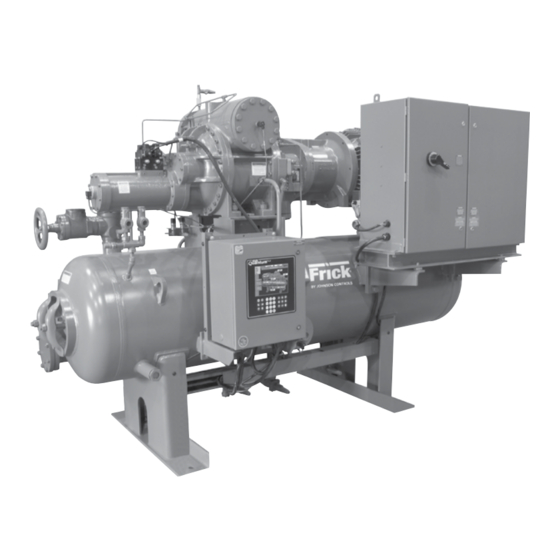
ROTARY SCREW COMPRESSOR UNITS
THIS MANUAL CONTAINS RIGGING, ASSEMBLY, START-UP,
AND MAINTENANCE INSTRUCTIONS. READ THOROUGHLY
BEFORE BEGINNING INSTALLATION. FAILURE TO FOLLOW THESE
INSTRUCTIONS MAY RESULT IN PERSONAL INJURY OR DEATH,
DAMAGE TO THE UNIT, OR IMPROPER OPERATION.
Please check www.johnsoncontrols.com/frick for the latest version of this publication.
Form 070.610-IOM (JUN 2011)
INSTALLATION - OPERATION - MAINTENANCE
File:
Replaces:
Dist:
RWF II
ALL REFRIGERANTS
MODELS
100 through 1080
SERVICE MANUAL - Section 70
070-610 IOM (MAR 2011)
3, 3a, 3b, 3c
Advertisement
Table of Contents
Troubleshooting

Related Manuals for Johnson Controls Frick RWF II


Summary of Contents for Johnson Controls Frick RWF II
- Page 1 Form 070.610-IOM (JUN 2011) INSTALLATION - OPERATION - MAINTENANCE File: SERVICE MANUAL - Section 70 Replaces: 070-610 IOM (MAR 2011) Dist: 3, 3a, 3b, 3c RWF II ROTARY SCREW COMPRESSOR UNITS ALL REFRIGERANTS MODELS 100 through 1080 THIS MANUAL CONTAINS RIGGING, ASSEMBLY, START-UP, AND MAINTENANCE INSTRUCTIONS.
-
Page 2: Table Of Contents
070.610-IOM (JUN 11) RWF II ROTARY SCREW COMPRESSOR UNITS Page 2 INSTALLATION - OPERATION - MAINTENANCE Contents PREFACE................3 BALANCE.PISTON.PRESSURE.REGULATOR....22 DESIGN.LIMITATIONS............3 INITIAL.START-UP............23 JOB.INSPECTION..............3 INITIAL.START-UP.PROCEDURE........23 TRANSIT.DAMAGE.CLAIMS..........3 NORMAL.START-UP.PROCEDURE........23 COMPRESSOR.and.UNIT.IDENTIFICATION....3 MAINTENANCE COMPRESSOR.IDENTIFICATION........4 GENERAL.INFORMATION..........24 INSTALLATION NORMAL.MAINTENANCE.OPERATIONS.......24 FOUNDATION..............5 GENERAL.MAINTENANCE..........24 RIGGING.and.HANDLING..........5 COMPRESSOR.SHUTDOWN.and.START-UP. -
Page 3: Preface
Immediately upon delivery examine all crates, boxes and serviceman with the INSTALLATION, OPERATION, and MAIN exposed compressor and com ponent surfaces for dam age. TEN ANCE procedures as recommended by Johnson Controls Unpack all items and check against shipping lists for any for Frick RWF II Rotary Screw Compres sor Units. -
Page 4: Compressor.identification
070.610-IOM (JUN 11) RWF II ROTARY SCREW COMPRESSOR UNITS Page 4 GENERAL INFORMATION COMPRESSOR IDENTIFICATION Each compressor has an identification data plate (see below), containing compressor model and serial number mounted on the compressor body. COMPRESSOR DATA PLATE Rotary screw compressor serial numbers are defined by the following information: EXAMPLE: 10240A90000015Z GLOBAL ADDITIONAL... -
Page 5: Installation
RWF II ROTARY SCREW COMPRESSOR UNITS 070.610-IOM (JUN 11) INSTALLATION Page 5 Installation disconnected from the compressor. See table for Allowable Flange Loads. FOUNDATION ALLOWABLE FLANGE LOADS NOZ. MOMENTS (ft-lbf) LOAD (lbf) If RWF II Rotary Screw Compressor Unit is shipped mounted SIZE AXIAL VERT. -
Page 6: Checking Motor/Compress Or Rota Tion
070.610-IOM (JUN 11) RWF II ROTARY SCREW COMPRESSOR UNITS Page 6 INSTALLATION CHECKING MOTOR/COMPRESS OR ROTA TION place the spacer between the two hub flanges. Care should be taken when handling the spacer. Be sure the spacer is Make sure coupling hubs are tight- fully supported at this time. -
Page 7: Oil.pump.coupling
Should additional heating capacity be required because of low ambient temperature, All units must be kept in a clean, dry location to prevent contact Johnson ControlsFrick . The heaters are energized corrosion damage. Reasonable consideration must be given ®... -
Page 8: Suction.isolation.valve.mounting
070.610-IOM (JUN 11) RWF II ROTARY SCREW COMPRESSOR UNITS Page 8 INSTALLATION The.oil.filter(s).and.coalescer.element(s).shipped.with.the. EQUIPMENT The basic equipment required for a ther mosyphon system consists of: unit.are.best.suited.to.ensure.proper.filtration.and.operation. of.the.system. 1. A source of liquid refrigerant at condensing pressure and temperature, located in close proximity to the unit to mini SUCTION ISOLATION VALVE MOUNTING mize piping pressure drop. -
Page 9: Liquid.injection.oil.cooling.(Optional)
RWF II ROTARY SCREW COMPRESSOR UNITS 070.610-IOM (JUN 11) INSTALLATION Page 9 outside of the shaded area on the piping diagram with con ator tube to ensure continued oil cooling when the receiver sideration given to the following: level is low. 1. -
Page 10: Economizer.-.High.stage.(Optional)
070.610-IOM (JUN 11) RWF II ROTARY SCREW COMPRESSOR UNITS Page 10 INSTALLATION your local distributor, but they must be suitable for stainless compressor capaciti es in cases where efficien cy is not as steel. The oil cooler may be cleaned in place by back flushing important as assuring that the liquid supply is subcooled. -
Page 11: Economizer.load.balancing
RWF II ROTARY SCREW COMPRESSOR UNITS 070.610-IOM (JUN 11) INSTALLATION Page 11 If the backpressure regulator valve is not used on a flash 1. Use the economizer output from the microprocessor to economizer, it is possible that no pressure difference will exist turn off a solenoid, or to actuate the electric shutoff option to drive liquid from the flash vessel to the evaporators, since on a backpressure regulator, based on percent of slide valve... -
Page 12: Motor.starter.package
Motor starter and interlock wiring require ments are shown in the Starter Wiring Diagram. All of the equipment shown is supplied by the installer unless a starter package is pur chased separately from Johnson ControlsFrick . Starter ® packages should consist of: 1. -
Page 13: Current.transformer.(Ct).Ratios
RWF II ROTARY SCREW COMPRESSOR UNITS 070.610-IOM (JUN 11) INSTALLATION Page 13 MINI MUM BURDEN RATINGS The.following.table.gives.the.minimum.CT.burden.ratings.. This.is.a.function.of.the.distance.between.the.motor.starting. package.and.the.compressor.unit. BURDEN MAXIMUM DISTANCE FROM RATING FRICK PANEL USING # USING # USING # ANSI 14 AWG 12 AWG 10 AWG B-0.1 15.ft 25.ft 40.ft... -
Page 14: Operation
070.610-IOM (JUN 11) RWF II ROTARY SCREW COMPRESSOR UNITS Page 14 OPERATION shaft. See Figure 15. The compressor should never be Operation operated in reverse rotation as bearing damage will result. OPERATION and START-UP INSTRUCTIONS The Frick RWF II Rotary Screw Compressor Unit is an inte ®... -
Page 15: Demand.pump.oil.system
RWF II ROTARY SCREW COMPRESSOR UNITS 070.610-IOM (JUN 11) OPERATION Page 15 DEMAND PUMP OIL SYSTEM COLD-START SYSTEM This system is designed to provide adequate compressor The RWF II package is equipped with a special "coldstart" lubrication when there is low differential oil pressure across discharge check valve (Figure 17) on the gas outlet connec... -
Page 16: Compressor.hydraulic.system
070.610-IOM (JUN 11) RWF II ROTARY SCREW COMPRESSOR UNITS Page 16 OPERATION COMPRESSOR HYDRAULIC SYSTEM SEE HYDRAULIC SCHEMATIC The compressor hydraulic system moves the movable slide FOR FUNCTIONAL valve (MSV) to load and unload the compressor. It also moves VIEW OF VALVE the movable slide stop (MSS) to increase or decrease the OPERATION compressor’s volume ratio (Vi). -
Page 17: Single-Port.liquid.injection
RWF II ROTARY SCREW COMPRESSOR UNITS 070.610-IOM (JUN 11) OPERATION Page 17 Figure 19 - Port Locations SINGLE-PORT LIQUID INJECTION DUAL-PORT LIQUID INJECTION The singleport liquid injection system is desig ned to permit The dualport liquid injection system is design ed to obtain liquid refrigerant injection into one port on the compressor the most efficient compressor performance at high and low at any given moment and operates as outlined. -
Page 18: Quantum Lx.ez-Cool Ez-Cool .Liquid.injection Injection Adjustment Procedure
070.610-IOM (JUN 11) RWF II ROTARY SCREW COMPRESSOR UNITS Page 18 OPERATION QUANTUM LX EZ-COOL LIQUID INJECTION Description of Proportional Band and Gain setpoints: ™ ™ ADJUSTMENT PROCEDURE • Proportional Band – This setpoint determines the size of a region either above or below the Control Setpoint. Use.the.following.directions.to.set.up.and.tune.the.EZ-Cool. -
Page 19: Operation Of Danfoss Liquid Injection Valve
RWF II ROTARY SCREW COMPRESSOR UNITS 070.610-IOM (JUN 11) OPERATION Page 19 Figure 21 - PID Setup NOTES: 1. Set the “Liquid Slugging” Alarm and Shutdown setpoints to 90 to prevent nuisance shutdowns during the tuning process. Be sure to return these setpoints to their original values when finished. - Page 20 070.610-IOM (JUN 11) RWF II ROTARY SCREW COMPRESSOR UNITS Page 20 OPERATION • “Down” arrow push button (Figure 22) • Displays the actual value of a parameter. Decreases parameter number by 1 at each activation • Displays the function status by means of text (Figure 22). •...
- Page 21 RWF II ROTARY SCREW COMPRESSOR UNITS 070.610-IOM (JUN 11) OPERATION Page 21 Parameter list Display Factory Description Min. Max. Unit Comments (Standard Setting) Name Setting ICM OD ICM valve Opening Degree is displayed during normal operation. (Opening Degree) Running display value (see j01, j05). Internal main switch 1: Normal operation Main Switch...
-
Page 22: Suction.check.valve.bypass
070.610-IOM (JUN 11) RWF II ROTARY SCREW COMPRESSOR UNITS Page 22 OPERATION 3. Connect the power supply. and/or heat tracing of the compressor lube oil systems is highly recommended. 4. Release down arrow and up arrow push buttons. 5. When the display on ICAD (Figure 22) is alternating be When low ambient temperatures (below +20°F) are a pos... -
Page 23: Initial.start-Up
Initial start-up must be performed under the super vision 2. For proper and safe operation, the compressor must be of a Johnson Controls-Frick authorized start-up represen- run at the proper speed and discharge pressure. Exceeding tative to prevent voiding the compressor warranty. Prior design conditions creates a potential hazard. -
Page 24: Maintenance
070.610-IOM (JUN 11) RWF II ROTARY SCREW COMPRESSOR UNITS Page 24 MAINTENANCE Keep liquid injection valves properly adjusted and in good Maintenance condition to avoid flooding compressor with liquid. Liquid can cause a reduction in compressor life and in extreme cases GENERAL INFORMATION can cause complete failure. -
Page 25: Oil.filter.(Of-1).Main.single/Dual
RWF II ROTARY SCREW COMPRESSOR UNITS 070.610-IOM (JUN 11) MAINTENANCE Page 25 4. SLOWLY vent separator to lowside system pressure 6. Install a new element* and tighten the nut on the end using the bypass line on the suction trap. NOTE: Recover plate to 10 ftlb torque. -
Page 26: Coalescer.filter.element(S)
070.610-IOM (JUN 11) RWF II ROTARY SCREW COMPRESSOR UNITS Page 26 MAINTENANCE 9. Refer to CHANGING OIL, Steps 9 through 14. Excessive pressure from expanding refrigerant trapped between stop CHANGING OIL valve and solenoid may cause gasket and O-ring failure and uncontrolled refrigerant release. DO NOT MIX OILS of different 3. -
Page 27: Demand.pump.disassembly
RWF II ROTARY SCREW COMPRESSOR UNITS 070.610-IOM (JUN 11) MAINTENANCE Page 27 DEMAND PUMP DISASSEMBLY The rotary member of the seal will come out with rotor and shaft. BEFORE OPENING ANY VIKING PUMP 10. AS, AK, AL: Remove bearing retainer washer. The washer LIQUID CHAMBER (PUMPING CHAM- may have stayed with rotor and shaft when removed or is BER, RESERVOIR, JACKET, ETC.) -
Page 28: Demand.pump.assembly
070.610-IOM (JUN 11) RWF II ROTARY SCREW COMPRESSOR UNITS Page 28 MAINTENANCE DEMAND PUMP ASSEMBLY just con tacting the spring. Do not compress spring. Remove installa tion sleeve. Assembly Notes On Standard Mechanical Seal (Synthetic 7. Coat rotor shaft with refrigeration oil. Install shaft slowly Rubber Bellows Type) pushing until the ends of rotor teeth are just below the face NOTE: Read carefully before reassembling pump... -
Page 29: Thrust.bearing.adjustment
RWF II ROTARY SCREW COMPRESSOR UNITS 070.610-IOM (JUN 11) MAINTENANCE Page 29 AS, AK, AL: Install ball bearing into bearing housing. In stall 3. Do not stop pressing operation until bushing is in proper lip seal in bearing housing end cap. The lip should face to position. -
Page 30: Preventative.maintenance
070.610-IOM (JUN 11) RWF II ROTARY SCREW COMPRESSOR UNITS Page 30 MAINTENANCE 2. Low reading would indicate: d. Pump misaligned. a. Relief valve set too low e. Extra clearance on pumping elements may not be b. Relief valve poppet not seating properly. suffi cient for operating conditions. -
Page 31: Oil.quality.and.analysis
RWF II ROTARY SCREW COMPRESSOR UNITS 070.610-IOM (JUN 11) MAINTENANCE Page 31 4. Vibration readings can be influenced by other equip ment oil foaming, nuisance oil level cutouts, oil pressure loss, operating in the vicinity or connected to the same piping as gas or oil leakage and catastrophic compressor failure. -
Page 32: Oil.sampling.procedure
070.610-IOM (JUN 11) RWF II ROTARY SCREW COMPRESSOR UNITS Page 32 MAINTENANCE 3. Oil samples for analysis should be taken after the oil filter. OPERATING LOG A 1/4" purge valve is provided in the oil filter canister head. The use of an operating log as included in this manual (see OIL SAMPLING PROCEDURE Table of Contents) permits thorough analysis of the operation of a refrigeration system by those responsible for its mainte... -
Page 33: Troubleshooting.guide
RWF II ROTARY SCREW COMPRESSOR UNITS 070.610-IOM (JUN 11) MAINTENANCE Page 33 Figure 36 TROUBLESHOOTING GUIDE to other problems. Under low load conditions the liquid in jection system may have a tendency to overfeed. The high Successful problem solving requires an organized ap proach to suction superheat condition, moreover, may only be tem... -
Page 34: Servicing.the.cold-Start.valve
070.610-IOM (JUN 11) RWF II ROTARY SCREW COMPRESSOR UNITS Page 34 MAINTENANCE 11. Incorrect refrigerant line sizing. Be extremely careful when disman- tling the cold-start valve on the 12. Improper system piping. discharge side of the unit, as con- densed refrigerant often is trapped between the cold-start 13. -
Page 35: Pressure.transducers.-.Testing
RWF II ROTARY SCREW COMPRESSOR UNITS 070.610-IOM (JUN 11) MAINTENANCE Page 35 3. Refer to the WIRING HARNESS section, External Transduc PRESSURE TRANSDUCERS - TESTING ers for Board #1, to identify the wiring harness connectors. 1. Shut down the compressor and allow pressures to equalize. 4. -
Page 36: Volume Ratio Control Transmitter - Slide Stop
070.610-IOM (JUN 11) RWF II ROTARY SCREW COMPRESSOR UNITS Page 36 MAINTENANCE CAPACITY LINEAR TRANSMITTER - VOLUME RATIO CONTROL TRANSMITTER - SLIDE VALVE SLIDE STOP REPLACEMENT TROUBLESHOOTING The Capacity Linear Transmitter is located on the end of the Confirm the setup of channel 15 on the calibration or analog compressor unload cylinder, see Figure 38. -
Page 37: Oil.level.transmitter
RWF II ROTARY SCREW COMPRESSOR UNITS 070.610-IOM (JUN 11) MAINTENANCE Page 37 not shorted to ground but is most likely open. Do continuity The linear transmitter with hermetic enclosure is based on tests to determine if it is the wiring or the sensor that is the capacitive measuring principle. -
Page 38: Troubleshooting.the.rwf.ii.compressor
070.610-IOM (JUN 11) RWF II ROTARY SCREW COMPRESSOR UNITS Page 38 MAINTENANCE TROUBLESHOOTING THE RWF II COMPRESSOR SYMPTOM PROBABLE CAUSES and CORRECTIONS EXCESSIVE NOISE and VIBRATION Main oil injection valve may be closed. Open valve. Main oil injection valve may be open too far. Adjust. Bearing damage or excessive wear. -
Page 39: The.hydraulic.system
RWF II ROTARY SCREW COMPRESSOR UNITS 070.610-IOM (JUN 11) MAINTENANCE Page 39 TROUBLESHOOTING THE HYDRAULIC SYSTEM SYMPTOM PROBABLE CAUSES and CORRECTIONS SLIDE VALVE WILL NOT LOAD OR Solenoid coils may be burned out. Test and replace if necessary. UNLOAD Valve may be closed. Open hydraulic service valves. Solenoid spool may be stuck or centering spring broken. -
Page 40: The.demand.pump.system
070.610-IOM (JUN 11) RWF II ROTARY SCREW COMPRESSOR UNITS Page 40 MAINTENANCE TROUBLESHOOTING THE DEMAND PUMP SYSTEM SYMPTOM PROBABLE CAUSES and CORRECTIONS PUMP.WILL.NOT.PRODUCE. Check.pump.rotation. ENOUGH.OIL.PRESSURE Check.that.service.valves.are.open. TO.START.COMPRESSOR Filter.cartridges.may.be.blocked...Check.PSID.across.filters. Strainer.may.be.blocked..Clean. Oil.pressure.regulator.set.too.low.or.stuck.open...Readjust.or.repair. Pump.worn.out..Repair.or.replace. OIL.PRESSURE.RAPIDLY.DROPS Main.oil.injection.throttling.valve.too.wide.open.or.oil.pressure OFF.WHEN.COMPRESSOR.STARTS regulating.valve.improperly.adjusted...Readjust.both.valves. RESULTS.IN.COMPRESSOR DIFFERENTIAL.ALARM OIL.PRESSURE.FLUCTUATES Liquid.injection.overfeeding.or.refrigerant.flood.back.from.system...Make necessary.adjustments.or.correc. t ions NOISE.and.VIBRATION Pump.strainer.blocked..Clean. -
Page 41: Compressor.port.locations
RWF II ROTARY SCREW COMPRESSOR UNITS 070.610-IOM (JUN 11) MAINTENANCE Page 41 COMPRESSOR PORT LOCATIONS - RWF II 100/134 PORT THREAD SIZE O-RING SB-3 1Z\zn-12.UN-2B 980A0012K66 SC-5 9/16-18.UNF-2B 980A0012K60 SC-6 9/16-18.UNF-2B 980A0012K60 SC-8 1Z\zn-12.UN-2B 980A0012K66 SC-9 9/16-18.UNF-2B 980A0012K60 SC-13 9/16-18.UNF-2B 980A0012K60 SC-14 9/16-18.UNF-2B... - Page 42 070.610-IOM (JUN 11) RWF II ROTARY SCREW COMPRESSOR UNITS Page 42 MAINTENANCE COMPRESSOR PORT LOCATIONS - RWF II 177/222/270 PORT THREAD SIZE O-RING SB-3 1Z\zn-12.UN-2B 980A0012K66 SC-5 9/16-18.UNF-2B 980A0012K60 SC-6 9/16-18.UNF-2B 980A0012K60 SC-8 1Z\zn-12.UN-2B 980A0012K66 SC-9 9/16-18.UNF-2B 980A0012K60 SC-11 1B\zn-12.UN-2B 980A0012K69 SC-13 9/16-18.UNF-2B...
- Page 43 RWF II ROTARY SCREW COMPRESSOR UNITS 070.610-IOM (JUN 11) MAINTENANCE Page 43 COMPRESSOR PORT LOCATIONS - RWF II 316/399 PORT THREAD SIZE O-RING SC-5 3/4-16.UNF-2B 980A0012K62 SC-6 9/16-18.UNF-2B 980A0012K60 SC-8 1B\zn-12.UN-2B 980A0012K69 SC-9 9/16-18.UNF-2B 980A0012K60 SC-13 9/16-18.UNF-2B 980A0012K60 SC-14 9/16-18.UNF-2B 980A0012K60 SD-1 1Z\zn-12.UN-2B 980A0012K66...
- Page 44 070.610-IOM (JUN 11) RWF II ROTARY SCREW COMPRESSOR UNITS Page 44 MAINTENANCE COMPRESSOR PORT LOCATIONS - RWF II 480/546 PORT THREAD SIZE O-RING SC-5 3/4-16.UNF-2B 980A0012K62 SC-6 9/16-18.UNF-2B 980A0012K60 SC-8 1B\zn-12.UN-2B 980A0012K69 SC-9 9/16-18.UNF-2B 980A0012K60 SC-13 9/16-18.UNF-2B 980A0012K60 SC-14 9/16-18.UNF-2B 980A0012K60 SD-1 1Z\zn-12.UN-2B 980A0012K66...
- Page 45 RWF II ROTARY SCREW COMPRESSOR UNITS 070.610-IOM (JUN 11) MAINTENANCE Page 45 COMPRESSOR PORT LOCATIONS - RWF II 496 PORT SIZE SB-2 3/4-14.NPTF SB-3 1½-11½.NPTF SC-3 1/2-14.NPTF SC-4 1/2-14.NPTF SC-5 3/8-18.NPTF SC-6 3/8-18.NPTF SC-7 1/8-27.NPTF SC-8 1¼-11½.NPTF SC-9 1½-11½.NPTF SC-10 1½-11½.NPTF SD-1 1/2-14.NPTF...
- Page 46 070.610-IOM (JUN 11) RWF II ROTARY SCREW COMPRESSOR UNITS Page 46 MAINTENANCE COMPRESSOR PORT LOCATIONS - RWF II 676 PORT SIZE SB-2 3/4-14.NPTF SB-3 1½-11½.NPTF SC-3 1/2-14.NPTF SC-4 1/2-14.NPTF SC-5 3/8-18.NPTF SC-6 3/8-18.NPTF SC-7 1/8-27.NPTF SC-8 1¼-11½.NPTF SC-9 1½-11½.NPTF SC-10 1½-11½.NPTF SD-1 1/2-14.NPTF...
- Page 47 RWF II ROTARY SCREW COMPRESSOR UNITS 070.610-IOM (JUN 11) MAINTENANCE Page 47 COMPRESSOR PORT LOCATIONS - RWF II 856 PORT SIZE SB-2 3/4-14.NPTF SB-3 1½-11½.NPTF SC-3 1/2-14.NPTF SC-4 1/2-14.NPTF SC-5 3/8-18.NPTF SC-6 3/8-18.NPTF SC-7 1/8-27.NPTF SC-8 1¼-11½.NPTF SC-9 1½-11½.NPTF SC-10 1½-11½.NPTF SD-1 1/2-14.NPTF...
- Page 48 070.610-IOM (JUN 11) RWF II ROTARY SCREW COMPRESSOR UNITS Page 48 MAINTENANCE COMPRESSOR PORT LOCATIONS - RWF II 1080 PORT SIZE SB-2 3/4-14.NPTF SB-3 1½-11½.NPTF SC-3 1/2-14.NPTF SC-4 1/2-14.NPTF SC-5 3/8-18.NPTF SC-6 3/8-18.NPTF SC-7 1/8-27.NPTF SC-8 1¼-11½.NPTF SC-9 1½-11½.NPTF SC-10 1½-11½.NPTF SD-1 1/2-14.NPTF...
-
Page 49: P.&.I.diagram
RWF II ROTARY SCREW COMPRESSOR UNITS 070.610-IOM (JUN 11) MAINTENANCE Page 49 P & I DIAGRAM See Legend next page! - Page 50 070.610-IOM (JUN 11) RWF II ROTARY SCREW COMPRESSOR UNITS Page 50 MAINTENANCE P & I DIAGRAM - OPTIONAL DUAL OIL FILTERS AND DEMAND OIL PUMP LEGEND.(Covers.all.P.&.I.diagrams.in.this.manual) TSH. TEMPERATURE.SWITCH.HIGH.ALARM COMPRESSOR CHECK.VALVE THERMOWELL VI.CONTROL DISCHARGE.PRESSURE SB-2. INLET.BEARING.&.BALANCE.PISTON FLOW.GLASS SB-3. DISCHARGE.BEARINGS.&.SEAL HAND.VALVE SC-1. SLIDE.VALVE.-.UNLOAD HTR.
- Page 51 RWF II ROTARY SCREW COMPRESSOR UNITS 070.610-IOM (JUN 11) MAINTENANCE Page 51 P & I DIAGRAM, LIQUID INJECTION – SINGLE PORT P & I DIAGRAM, LIQUID INJECTION – DUAL PORT...
-
Page 52: Proper Installation Of Electronic Equipment In An Industrial Environment
070.610-IOM (JUN 11) RWF II ROTARY SCREW COMPRESSOR UNITS Page 52 PROPER INSTALLATION OF ELECTRONIC EQUIPMENT PROPER INSTALLATION OF ELECTRONIC EQUIPMENT IN AN INDUSTRIAL ENVIRONMENT In today’s refrigeration plants, electronic controls have to its maximum capacity, the voltage dips are much larger, found their way into almost every aspect of refrigeration and the potential of a malfunction is very high. - Page 53 This worked for the earlier relay systems, but it is in no way acceptable for electronic control equipment. Johnson ControlsFrick requires that the ground conductor ® Conduit is made of steel and is a poor conductor relative meet the following: to an insulated stranded copper wire.
- Page 54 In addition, compressor package where the motor voltage is 480 volts Johnson Controls-Frick requirements must be followed and the electronic control panel power is 120 volts. The 480 where they exceed or match national or local codes. Con-...
- Page 55 RWF II ROTARY SCREW COMPRESSOR UNITS 070.610-IOM (JUN 11) PROPER INSTALLATION OF ELECTRONIC EQUIPMENT Page 55 ers recommend or provide prepunched conduit connections. Never daisy-chain or parallel-connect power or ground You may also be negating the NEMA rating of the enclosure. wires to electronic control panels.
- Page 56 LX PANELS ™ The use of communications such as serial and ethernet Johnson Controls, Inc. does not advise nor support the use in industrial environments are commonplace. The proper of uninterrupted power supply systems for use with the installation of these networks is as important to the proper Quantum LX panel.
-
Page 57: Forms
RWF II ROTARY SCREW COMPRESSOR UNITS 070.610-IOM (JUN 11) MAINTENANCE Page 57 OPERATING LOG SHEET... - Page 58 070.610-IOM (JUN 11) RWF II ROTARY SCREW COMPRESSOR UNITS Page 58 MAINTENANCE RWF II COMPRESSOR PRESTART CHECKLIST The following items MUST be checked and completed by the installer prior to the arrival of the Frick Field Service Supervisor. Details on the checklist can be found in this manual. Certain items on this checklist will be reverified by the Frick Field Service Supervisor prior to the actual start-up.
- Page 59 RWF II ROTARY SCREW COMPRESSOR UNITS 070.610-IOM (JUN 11) MAINTENANCE Page 59 Start-up Report Frick Order No: ________________________ Sold To: _______________________________________ Contact Name:__________________________ Date:__________________ End User: ______________________________________ Contact Name:__________________________ Phone:__________________ End User Address: ______________________________________________________________________ Fax No:__________________ City, State, Zip: _________________________________ Startup Representative _________________ Unit General Information Unit Model # ___________________________________________ Customer Package Identification # _________________________ Compressor Serial # _____________________________________ Separator National Board # ________________________________...
- Page 60 070.610-IOM (JUN 11) RWF II ROTARY SCREW COMPRESSOR UNITS Page 60 MAINTENANCE Page 2 Unit Serial # _____________________________ Frick Order No: ____________________________ Capacity Control Setpoints Mode __________________ Mode __________________ Setpoint ________ Regulation Safeties Setpoint ________ Regulation Safeties High Load Inhibit ________ High Load Inhibit _________ Prop.
- Page 61 RWF II ROTARY SCREW COMPRESSOR UNITS 070.610-IOM (JUN 11) MAINTENANCE Page 61 Page 3 Unit Serial # _____________________________ Frick Order No: ____________________________ Compressor Motor Setpoints and Information Motor Name Plate Manufacturer ________________ Motor Amps ___________ Maximum Drive Output ___ % Frame Size ______________ Volts ___________ Minimum Drive Output ___ %...
- Page 62 070.610-IOM (JUN 11) RWF II ROTARY SCREW COMPRESSOR UNITS Page 62 MAINTENANCE Page 4 Unit Serial # ________________ Frick Order No: __________________________________________ P&ID Setpoints Name _________________ __________ _________________ ____________ Control ____________ ____________ ____________ ____________ Action __________________ ____________ __________________ ____________ Control Point __________________ ____________ __________________ ____________ Device Source...
- Page 63 RWF II ROTARY SCREW COMPRESSOR UNITS 070.610-IOM (JUN 11) MAINTENANCE Page 63 VIBRATION DATA SHEET Date: __________________________________________ Sales Order Number: ________________________________ End User: _______________________________________ Installing Contractor: ________________________________ Address: __________________________________________ Service Technician: __________________________________ ___________________________________________________ ___________________________________________________ Equipment ID (As in Microlog): ____________________________ Compressor Model Number: __________________________________ Compressor Serial Number: __________________________________ Unit Serial Number: _________________________________________...
- Page 64 070.610-IOM (JUN 11) RWF II ROTARY SCREW COMPRESSOR UNITS Page 64 INDEX Index Symbols condensing pressure, 8 bent shaft, 30 condensing tempera ture, 8 cavitating, 30 3phase ground, 54 Conduit, 54 cavitation, 29 3phase supply, 54 cone/button, 8 Discharge Port, 29 constant speed starters, 54 Discharge pressure, 30 control power regulator, 13...
- Page 65 RWF II ROTARY SCREW COMPRESSOR UNITS 070.610-IOM (JUN 11) INDEX Page 65 flashing liquid, 10 Foundation, 5,14 flash economizer system, 10 Foundation leak test, 25 flash gas, 11 Anchor bolts, 5 levelcontrol method, 9 flash tank, 10 epoxy grout, 5 LICO, 17 flash vapor, 11 grout, 5...
- Page 66 070.610-IOM (JUN 11) RWF II ROTARY SCREW COMPRESSOR UNITS Page 66 INDEX liquid solenoid, 10,25 See Index, Oil temperature, 8 Troubleshooting. Trouble liquid supply service valve, 25 operating level, 7 shooting locknut, 6 Operating Log Sheet, 57 Troubleshooting Guide, 33 low differential oil pressure, 15 operating volume ratio, 17 Vibration Analysis, 30...
- Page 67 RWF II ROTARY SCREW COMPRESSOR UNITS 070.610-IOM (JUN 11) INDEX Page 67 "D" Flange adapter, 14 subcooling, 10 Troubleshooting Guide, 33 angularcontact ball bearings, 14 suction, 15 Troubleshooting The Demand Pump axial loads, 14 suction accumulators, 24 System, 40 axial load bearings, 14 suction bypass, 11 Troubleshooting The Hydraulic System, balance pistons, 14...
- Page 68 Johnson Controls Supersedes: 070-610 IOM (2011-03) 100 CV Avenue Subject to change without notice Waynesboro, PA 17268-1206 USA Published in USA • GUI • 0611 PDF Phone: 717-762-2121 • FAX: 717-762-8624 www.johnsoncontrols.com/frick © 2011 Johnson Controls Inc. - ALL RIGHTS RESERVED...
Need help?
Do you have a question about the Frick RWF II and is the answer not in the manual?
Questions and answers