Table of Contents
Advertisement
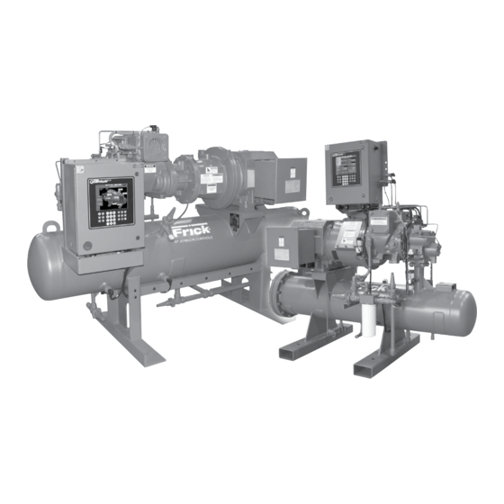
ROTARY SCREW COMPRESSOR UNITS
THIS MANUAL CONTAINS RIGGING, ASSEMBLY, START-UP,
AND MAINTENANCE INSTRUCTIONS. READ THOROUGHLY
BEFORE BEGINNING INSTALLATION. FAILURE TO FOLLOW THESE
INSTRUCTIONS MAY RESULT IN PERSONAL INJURY OR DEATH,
DAMAGE TO THE UNIT, OR IMPROPER OPERATION.
Please check www.johnsoncontrols.com/frick for the latest version of this publication.
Form 070.410-IOM (JAN 2012)
INSTALLATION - OPERATION - MAINTENANCE
File:
Replaces:
Dist:
RXF
MODELS 12 – 101
SERVICE MANUAL - Section 70
070.410-IOM (JUL 2011)
3, 3a, 3b, 3c
Advertisement
Table of Contents
Troubleshooting

Related Manuals for Johnson Controls Frick RXF 12


Summary of Contents for Johnson Controls Frick RXF 12
- Page 1 Form 070.410-IOM (JAN 2012) INSTALLATION - OPERATION - MAINTENANCE File: SERVICE MANUAL - Section 70 Replaces: 070.410-IOM (JUL 2011) Dist: 3, 3a, 3b, 3c ROTARY SCREW COMPRESSOR UNITS MODELS 12 – 101 THIS MANUAL CONTAINS RIGGING, ASSEMBLY, START-UP, AND MAINTENANCE INSTRUCTIONS. READ THOROUGHLY BEFORE BEGINNING INSTALLATION.
-
Page 2: Table Of Contents
070.410-IOM (JAN 12) RXF ROTARY SCREW COMPRESSOR UNITS Page 2 INSTALLATION - OPERATION - MAINTENANCE TABLE OF CONTENTS PREFACE................3 MAINTENANCE DESIGN LIMITATIONS ............3 NORMAL MAINTENANCE OPERATIONS ......22 JOB INSPECTION ..............3 GENERAL MAINTENANCE ..........22 TRANSIT DAMAGE CLAIMS ..........3 COMPRESSOR SHUTDOWN and START-UP ......22 UNIT IDENTIFICATION ............3 COMPRESSOR/MOTOR SERVICING ........22 GEOMETRICAL SWEPT VOLUME TABLE ...... -
Page 3: Preface
RXF Rotary Screw Compres sor Units. Contact Johnson Controls-Frick, Sales Administration It is most important that these units be properly applied to an Depart ment, in Waynesboro, PA to report dam age or short- adequately controlled refrigeration system. -
Page 4: Geometrical Swept Volume Table
070.410-IOM (JAN 12) RXF ROTARY SCREW COMPRESSOR UNITS Page 4 GENERAL INFORMATION COMPRESSOR DATA PLATE Rotary screw compressor serial numbers are defined by the following information: EXAMPLE: 10240A90000015Z GLOBAL ADDITIONAL PLANT DECADE MONTH YEAR SEQ NO. REMARKS 1024 0000015 Month: A = JAN, B = FEB, C = MAR, D = APR, E = MAY, F = JUN, G = JUL, H = AUG, K = SEP, L = OCT, M = NOV, N = DEC. -
Page 5: Installation
RXF ROTARY SCREW COMPRESSOR UNITS 070.410-IOM (JAN 12) INSTALLATION Page 5 Installation ALLOWABLE fLANGE LOADS NOZ. MOMENTS (ft-lbf) LOAD (lbf) SIZE AXIAL VERT. LAT. AXIAL VERT. LAT. FOUNDATION NOTE: Allow space for servicing both ends of the unit. A minimum of 24 inches is recommended. 1.25 The first requirement of the compressor foundation is that it must be able to support the weight of the compressor... -
Page 6: Skid Removal
070.410-IOM (JAN 12) RXF ROTARY SCREW COMPRESSOR UNITS Page 6 INSTALLATION RXF 58 – 101 units can be moved with rigging, using a crane COMPRESSOR/MOTOR COUPLINGS or forklift by hooking into three lifting points on the oil sepa- RXF units are arranged for direct motor drive and include a rator. -
Page 7: Compressor Oil
Failure to remove these contact Johnson Controls-Frick. The heater is energized only gauges may result in catastrophic failure of the gauge and when the unit is not in operation. -
Page 8: Thermosyphon Oil Cooling
070.410-IOM (JAN 12) RXF ROTARY SCREW COMPRESSOR UNITS Page 8 INSTALLATION THERMOSYPHON OIL COOLING EQUIPMENT: The basic equipment required for a thermo syphon system consists of: 1. A source of liquid refrigerant at condens- ing pressure and temperature located in close prox imity to the unit to minimize piping pres- sure drop. -
Page 9: Liquid Injection Oil Cooling
RXF ROTARY SCREW COMPRESSOR UNITS 070.410-IOM (JAN 12) INSTALLATION Page 9 4. Welding should occur in two segments, from 6:00 to 12:00. Liquid.line.sizes.and.the.additional.receiver.volume.(quanti- The maximum intersegment temperature should be 350°F. ty.of.refrigerant.required.for.5.minutes.of.liquid.injection.oil. Temperature should be verified with temperature indicating cooling).are.given.in.the.following.table: crayon or equivalent. FLOW 5. -
Page 10: Dual Dip Tube Method
070.410-IOM (JAN 12) RXF ROTARY SCREW COMPRESSOR UNITS Page 10 INSTALLATION receiver be oversized sufficiently to retain a 5-minute intermediate pressure is provided by a port located part way supply of refrigerant for oil cooling. The evaporator sup- down the compres sion process on the screw compressor. ply must be secondary to this considera tion. -
Page 11: Electrical
If the panel was in: The strainer must be strong enough to handle the gas pulsations from the compressor. Johnson Controls-Frick • Auto – Compressor motor will return to running as pro- recommends an R/S or Hansen strainer. -
Page 12: Mini Mum Burden Ratings
070.410-IOM (JAN 12) RXF ROTARY SCREW COMPRESSOR UNITS Page 12 INSTALLATION Motor starter and interlock wiring require ments are shown CURRENT TRANSFORMER SIZE in the diagram, Figure 12. All of the equipment shown is sup- Calculate (CT) size using the following formula where SF is plied by the installer unless a starter package is pur chased Service Factor and FLA is Full Load Amps of the Motor. -
Page 13: Operation
RXF ROTARY SCREW COMPRESSOR UNITS 070.410-IOM (JAN 12) OPERATION Page 13 COMPRESSOR LUBRICATION SYSTEM Operation The RXF compressor is designed specifically for operation OPERATION and START-UP INSTRUCTIONS without an oil pump for high stage service. Boosters and some low-differential pressure appli cations will require the The Frick RXF Rotary Screw Compressor Unit is an integrat ed demand pump option. -
Page 14: Demand Pump Oil System
070.410-IOM (JAN 12) RXF ROTARY SCREW COMPRESSOR UNITS Page 14 OPERATION tion pressure before it fully powers open. The heavier spring COMPRESSOR is not required because booster compressors are equipped HV-1 SUCTION with a demand oil pump. The RXF package is also equipped with a suction check valve bypass. -
Page 15: Volumizer ® Ii Vi Control
Slide valve calibration is performed on the Quantum™LX wrong compressor Vi can cause excessive power consump- control panel in automatic mode. If further problems occur tion, noise, vibration, or excessive oil foaming. See Figures or persist, contact Johnson Controls-Frick service. -
Page 16: Compressor Oil Cooling Systems
070.410-IOM (JAN 12) RXF ROTARY SCREW COMPRESSOR UNITS Page 16 OPERATION COMPRESSOR OIL COOLING SYSTEMS This minimizes the performance penalty incurred with liquid injection oil cooling. The RXF unit can be equipped with one of several systems The dual-port system contains all the com ponents of the for controlling the compressor oil tempera ture. - Page 17 RXF ROTARY SCREW COMPRESSOR UNITS 070.410-IOM (JAN 12) OPERATION Page 17 • Use the [ 0 ] key to change the Delta from 10 to 1, .10 or value of the Control Input by predicting the direction the .01% to tune the output to the objective of 4 or 20mA. Control Input is traveling and then turning it back toward the Control Setpoint.
-
Page 18: Operation Of Danfoss Liquid Injection Valve
070.410-IOM (JAN 12) RXF ROTARY SCREW COMPRESSOR UNITS Page 18 OPERATION 3. Tune the output by making small adjustments of 1-5 to the Proportional Band and .1-.5 of the Integral Gain setpoints. Adjust only one at a time, allowing each adjustment time to settle out. - Page 19 RXF ROTARY SCREW COMPRESSOR UNITS 070.410-IOM (JAN 12) OPERATION Page 19 • Alarms 5. Push the down arrow button again and scroll until j26 is displayed and push the enter button. Identify the ICM valve - If an alarm has been detected the ICAD display (Figure being used and push the up arrow until the correct number is 23) will alternate between showing Actual alarm and displayed for the ICM valve and then push the enter button.
- Page 20 070.410-IOM (JAN 12) RXF ROTARY SCREW COMPRESSOR UNITS Page 20 OPERATION PARAMETER LIST Display Factory Description Min. Max. Unit Comments Name Setting ICM OD ICM valve Opening Degree is displayed during normal operation. (Opening Degree) Running display value (see 05). Internal main switch 1: Normal operation Main Switch...
-
Page 21: Thermosyphon Oil Cooling
RXF ROTARY SCREW COMPRESSOR UNITS 070.410-IOM (JAN 12) OPERATION Page 21 THERMOSYPHON OIL COOLING 1. On start-up the unit should be operated at as high a load possible for 3 hours. During the period, adjust liquid injection Thermosyphon oil cooling is an economical, effective method oil cooling, if applicable. -
Page 22: Maintenance
070.410-IOM (JAN 12) RXF ROTARY SCREW COMPRESSOR UNITS Page 22 MAINTENANCE cause a reduction in compressor life and in extreme cases MAINTENANCE can cause complete failure. This section provides instructions for normal maintenance, 5. Protect the compressor during long periods of shut down. a recommended maintenance program, troubleshooting and If the compressor will be setting for long periods without run- correction guides, typical wiring diagrams and typical P and... -
Page 23: General Instructions For Replacing Compressor Unit Components
RXF ROTARY SCREW COMPRESSOR UNITS 070.410-IOM (JAN 12) MAINTENANCE Page 23 between the separator shell and compressor casting. Make SLOWLY vent separator to low-side system pressure using sure the weight is held safely by the separator shell. Loosen the suction check valve bypass. NOTE: Recover or transfer the compressor discharge flange bolts to relax any flange all refrigerant vapor, in accor dance with local ordinances, and pipe stress, then carefully remove the motor. -
Page 24: Coalescer Oil Return Strainer
070.410-IOM (JAN 12) RXF ROTARY SCREW COMPRESSOR UNITS Page 24 MAINTENANCE suction check valve bypass. Close disconnect switches for 8. Reassemble the strainer. the compressor and (if applicable) the oil pump motor start- 9. Open the service valve between the compressor and the ers. -
Page 25: Changing Oil
RXF ROTARY SCREW COMPRESSOR UNITS 070.410-IOM (JAN 12) MAINTENANCE Page 25 When changing the coalescer filter element, it is recom- 10. Open suction service valve and pressurize the unit to mended that the oil and oil filter be changed. Applicable system suction pressure. -
Page 26: Demand Pump Disassembly
070.410-IOM (JAN 12) RXF ROTARY SCREW COMPRESSOR UNITS Page 26 MAINTENANCE DEMAND PUMP DISASSEMBLY hammer, use a piece of hardwood between the shaft and hammer. The rotary member of the seal will come out with BEFORE OPENING ANY VIKING PUMP the rotor and shaft. -
Page 27: Demand Pump Assembly
RXF ROTARY SCREW COMPRESSOR UNITS 070.410-IOM (JAN 12) MAINTENANCE Page 27 DEMAND PUMP ASSEMBLY just con tacting the spring. Do not compress the spring. Re- move the installa tion sleeve. Assembly Notes On Standard Mechanical Seal (Synthetic 7. Coat the rotor shaft with refrigeration oil. Install the rotor Rubber Bellows Type) and shaft into the casing, slowly pushing until the ends of NOTE: Read carefully before reassembling pump... -
Page 28: Troubleshooting The Demand Pump
070.410-IOM (JAN 12) RXF ROTARY SCREW COMPRESSOR UNITS Page 28 MAINTENANCE 15. Pack the double row ball bearing with multi-purpose INSTALLATION OF grease, NLGI #2. CARBON GRAPHITE BUSHINGS GG, HJ, HL: Install the ball bearing into the bearing housing When installing carbon graphite bushings, extreme care must with shield side toward the coupling end of the shaft. -
Page 29: Recommended Maintenance Program
RXF ROTARY SCREW COMPRESSOR UNITS 070.410-IOM (JAN 12) MAINTENANCE Page 29 Pressure gauge - Discharge Port f. Pump worn out. g. Tighten end clearance. 1. High reading would indicate: h. Head position incorrect. a. High viscosity and small and/or long discharge line. 5. -
Page 30: Maintenance Schedule
070.410-IOM (JAN 12) RXF ROTARY SCREW COMPRESSOR UNITS Page 30 MAINTENANCE NOTE: The Frick oil charge shipped with the unit is the best suited lubricant for the conditions specified at the time of purchase. If there is any doubt due to the refriger- ant, operating pressures, or temperatures, refer to Frick Oil publication 160-802 SPC for guidance. -
Page 31: Motor Bearings
RXF ROTARY SCREW COMPRESSOR UNITS 070.410-IOM (JAN 12) MAINTENANCE Page 31 Figure 33 MOTOR BEARINGS The first step in effective problem solving is to define the limits of the problem. If, for example, the compres sor pe- Lubricate motor bearings properly riodically experienc es high oil tempera tures, do not rely on before start-up. -
Page 32: Pressure Transducers - Testing
070.410-IOM (JAN 12) RXF ROTARY SCREW COMPRESSOR UNITS Page 32 MAINTENANCE pRESSURE TRANSDUCER CONVERSION DATA 100 psi 200 psi 300 psi 500 psi Range - pSIG* Range - pSIG* Range - pSIG* Range - pSIG* Sensor Voltage high high high high 29.92"... -
Page 33: Pressure Transducers Replacement
RXF ROTARY SCREW COMPRESSOR UNITS 070.410-IOM (JAN 12) MAINTENANCE Page 33 an allowance in the readings must be made by subtracting 6. Recalibrate. NOTE: If replacing older hard-wired trans- approximately 0.02 VDC per 1000 feet of elevation above ducer, cut cable at back of old transducer and rewire to sea level. -
Page 34: Oil Level Transmitter Replacement
070.410-IOM (JAN 12) RXF ROTARY SCREW COMPRESSOR UNITS Page 34 MAINTENANCE NOTE: For calibration instructions, refer to Quantum™ LX If it is necessary to replace the well, Operator's Manual 090-020 O, -021 O, -022 O. the separator must be purged and the oil drained. -
Page 35: Troubleshooting The Compressor
RXF ROTARY SCREW COMPRESSOR UNITS 070.410-IOM (JAN 12) MAINTENANCE Page 35 TROUBLESHOOTING THE COMPRESSOR SYMpTON pROBABLE CAUSES and CORRECTIONS EXCESSIVE NOISE and Loose bolts on compressor mounting. Tighten bolts. VIBRATION No oil getting to compressor. Check oil level, oil filter and oil pressure. Bearing damage or excessive wear. -
Page 36: Hydraulic System
070.410-IOM (JAN 12) RXF ROTARY SCREW COMPRESSOR UNITS Page 36 MAINTENANCE TROUBLESHOOTING THE HYDRAULIC SYSTEM SYMpTOM pROBABLE CAUSES and CORRECTIONS SLIDE VALVE WILL NOT LOAD Solenoid coil burned out. Replace coil. OR UNLOAD HV2 needle valve closed. Open valve. Solenoid spool may be stuck or centering spring broken. Free spool or replace spring. Solenoid may be mechanically actuated by inserting a piece of 3/16"... -
Page 37: Compressor Port Locations
RXF ROTARY SCREW COMPRESSOR UNITS 070.410-IOM (JAN 12) MAINTENANCE Page 37 COMPRESSOR PORT LOCATIONS - RXF 12 - 19 PORT CONNECTION SIZE 3/4.-.14.NPTF 3/8.-.18.NPTF 3/8.-.18.NPTF 3/4.-.14.NPTF 1/4.-.18.NPTF 3/8.-.18.NPTF 1/4.-.18.NPTF 1/4.-.18.NPTF 1/4.-.18.NPTF 3/4.-.14.NPTF 1/2.-.14.NPTF 1/4.-.18.NPTF 3/4.-.14.NPTF 1/4.-.18.NPTF... - Page 38 070.410-IOM (JAN 12) RXF ROTARY SCREW COMPRESSOR UNITS Page 38 MAINTENANCE COMPRESSOR PORT LOCATIONS - RXF 24 - 50 PORT CONNECTION SIZE 1.-.11½.NPTF 1/4.-.18.NPTF 3/8.-.18.NPTF 3/8.-.18.NPTF 1.-.11½.NPTF 1/2.-.14.NPTF 1/4.-.18.NPTF 1/4.-.18.NPTF 1/4.-.18.NPTF 1/4.-.18.NPTF 1/4.-.18.NPTF 3/8.-.18.NPTF 3/4.-.14.NPTF 1/8.-.27.NPTF 1/4.-.18.NPTF 1/8.-.27.NPTF 3/8.-.18.NPTF 1/4.-.18.NPTF...
-
Page 39: Sae Straight Thread O-Ring Fittings - Assembly Procedure
RXF ROTARY SCREW COMPRESSOR UNITS 070.410-IOM (JAN 12) MAINTENANCE Page 39 SAE STRAIGHT THREAD O-RING FITTINGS - ASSEMBLY PROCEDURE FOR RXF 58 - 101 When performing maintenance or replacing the compres- 1. Inspect components to ensure that male and female port sor, the hydraulic tubing may need to be removed and threads and sealing surfaces are free of burrs, nicks and re-installed. - Page 40 070.410-IOM (JAN 12) RXF ROTARY SCREW COMPRESSOR UNITS Page 40 MAINTENANCE COMPRESSOR PORT LOCATIONS - RXF 58 - 101 PORT CONNECTION SIZE 1Z\zn.-.12UN-2B 7/16.-.20UNF-2B 1Z\zn.-.12UN-2B 1Z\zn.-.12UN-2B 1M\,.-.12UN-2B 9/16.-.18UNF-2B 1Z\zn.-.12UN-2B 7/16.-.20UNF-2B 9/16.-.18UNF-2B 9/16.-.18UNF-2B 3/4.-.14.NPTF 1Z\zn.-.12UN-2B 1/4.-.18.NPTF 1/8.-.27.NPTF 1/2.-.14.NPTF 9/16.-.18UNF-2B 1Z\zn.-.12UN-2B 9/16.-.18UNF-2B...
-
Page 41: P & I Diagram
RXF ROTARY SCREW COMPRESSOR UNITS 070.410-IOM (JAN 12) MAINTENANCE Page 41 P & I DIAGRAM, LIQUID INJECTION – SINGLE PORT COMPRESSOR LOW VI, COMPRESSOR ECONOMIZER, OR HIGH VI, CLOSED THREAD BOOSTER ONLY TUBING LINE SOLENOID MOTORIZED VALVE STRAINER EXPANSION VALVE LIQUID REFRIGERANT FROM RECEIVER LIQUID LINE... - Page 42 070.410-IOM (JAN 12) RXF ROTARY SCREW COMPRESSOR UNITS Page 42 MAINTENANCE RXF MODELS 12 throughy 50 without OIL PUMP (See OIL COOLING ADDITIONS) LEGEND* . . AS PUMP HIGH TEMPERATURE ALARM AIR SUPPLY HIGH PRESSURE ALARM TAHH HIGH TEMP. SHUTDOWN COMPRESSOR PAHH HIGH PRESSURE SHUTDOWN...
- Page 43 RXF ROTARY SCREW COMPRESSOR UNITS 070.410-IOM (JAN 12) MAINTENANCE Page 43 RXF MODELS 12 through 50 with OIL PUMP (See OIL COOLING ADDITIONS) LEGEND (Cont.) CONNECTIONS VENT - UNLOADING NOTES: THERMOWELL MAIN OIL SUPPLY 1. PRESSURE TRANSDUCERS INDICATE: SUCTION PRESSURE SLIDE VALVE PISTON PE-1 OIL PRESSURE LOW VI LIQUID INJECTION...
- Page 44 070.410-IOM (JAN 12) RXF ROTARY SCREW COMPRESSOR UNITS Page 44 MAINTENANCE RXF MODELS 58, 68, 85, & 101 without OIL PUMP (See OIL COOLING ADDITIONS) LEGEND* . . AS PUMP HIGH TEMPERATURE ALARM AIR SUPPLY HIGH PRESSURE ALARM TAHH HIGH TEMP. SHUTDOWN COMPRESSOR PAHH HIGH PRESSURE SHUTDOWN...
- Page 45 RXF ROTARY SCREW COMPRESSOR UNITS 070.410-IOM (JAN 12) MAINTENANCE Page 45 RXF Models 58, 68, 85, & 101 with OIL PUMP and DUAL OIL FILTERS ( See OIL COOLING ADDITIONS) LEGEND (Cont.) NOTES: CONNECTIONS MAIN OIL INJECTION MAIN OIL SUPPLY 1.
-
Page 46: Wiring Harness
070.410-IOM (JAN 12) RXF ROTARY SCREW COMPRESSOR UNITS Page 46 MAINTENANCE WIRING HARNESS - External for Analog Devices... - Page 47 RXF ROTARY SCREW COMPRESSOR UNITS 070.410-IOM (JAN 12) MAINTENANCE Page 47 WIRING HARNESS - AC to Heaters and Valves (External) WIRING HARNESS - AC Conduit - Quantum to DBS Panel...
-
Page 48: Proper Installation Of Electronic Equipment In An Industrial Environment
070.410-IOM (JAN 12) RXF ROTARY SCREW COMPRESSOR UNITS Page 48 PROPER INSTALLATION OF ELECTRICAL EQUIPMENT PROPER INSTALLATION OF ELECTRONIC EQUIPMENT IN AN INDUSTRIAL ENVIRONMENT In today’s refrigeration plants, electronic controls have loaded to its maximum capacity, the voltage dips are much found their way into almost every aspect of refrigeration larger, and the potential of a malfunction is very high. -
Page 49: Grounding
RXF ROTARY SCREW COMPRESSOR UNITS 070.410-IOM (JAN 12) PROPER INSTALLATION OF ELECTRICAL EQUIPMENT Page 49 GROUNDING NEC size ratings are for safety purposes and not necessarily for adequate relaying of noise (EMI) to earth ground to avoid Grounding is the most important factor for successful opera- possible interference with sensitive equipment. -
Page 50: Conduit
In addition, in its own conduit. The 120 volt circuit must be run from the Johnson Controls-Frick requirements must be followed motor starter control transformer to the electronic control where they exceed or match national or local codes. Con- panel in its own separate conduit. - Page 51 RXF ROTARY SCREW COMPRESSOR UNITS 070.410-IOM (JAN 12) PROPER INSTALLATION OF ELECTRICAL EQUIPMENT Page 51 Drilling can cause metal filings to land on the electronics and Never daisy-chain or parallel-connect power or ground create a short circuit when powered is applied. If you must wires to electronic control panels.
-
Page 52: Communications
LX PANELS ™ The use of communications such as serial and ethernet Johnson Controls, Inc. does not advise nor support the use in industrial environments are commonplace. The proper of uninterrupted power supply systems for use with the installation of these networks is as important to the proper Quantum LX panel. -
Page 53: Forms
RXF ROTARY SCREW COMPRESSOR UNITS 070.410-IOM (JAN 12) FORMS Page 53 FORMS ROTARY SCREW COMPRESSOR OPERATING LOG SHEET... - Page 54 070.410-IOM (JAN 12) RXF ROTARY SCREW COMPRESSOR UNITS Page 54 FORMS READ THIS FIRST: COMPRESSOR PRESTART CHECKLIST The following items MUST be checked and completed by the installer prior to the arrival of the Frick Field Service Supervisor. Details on the checklist can be found in this manual. Certain items on this checklist will be reverified by the Frick Field Service Supervisor prior to the actual start-up.
- Page 55 RXF ROTARY SCREW COMPRESSOR UNITS 070.410-IOM (JAN 12) FORMS Page 55 Start-up Report Frick Order No: ________________________ Sold To: _______________________________________ Contact Name:__________________________ Date:__________________ End User: ______________________________________ Contact Name:__________________________ Phone:__________________ End User Address: ______________________________________________________________________ Fax No:__________________ City, State, Zip: _________________________________ Start-up Representative _________________ Unit General Information Unit Model # ___________________________________________ Customer Package Identification # _________________________ Compressor Serial # _____________________________________ Separator National Board # ________________________________...
- Page 56 070.410-IOM (JAN 12) RXF ROTARY SCREW COMPRESSOR UNITS Page 56 FORMS Page 2 Unit Serial # _____________________________ Frick Order No: ____________________________ Capacity Control Setpoints Setpoint Regulation Safeties Setpoint Regulation Safeties High Load Inhibit ________ High Load Inhibit _________ Prop. Band ________ ________ Force Unload ________ Prop.
- Page 57 RXF ROTARY SCREW COMPRESSOR UNITS 070.410-IOM (JAN 12) FORMS Page 57 Page 3 Unit Serial # _____________________________ Frick Order No: ____________________________ Compressor Motor Setpoints and Information Motor Name Plate Manufacturer ________________ Motor Amps ___________ Maximum Drive Output ___ % Frame Size ______________ Volts ___________ Minimum Drive Output ___ % H.P.
- Page 58 070.410-IOM (JAN 12) RXF ROTARY SCREW COMPRESSOR UNITS Page 58 FORMS Page 4 Unit Serial # ________________ Frick Order No: __________________________________________ P&ID Setpoints Name _________________ __________ _________________ __________ Control ____________ ____________ ____________ ____________ Action ___________ ____________ ____________ ____________ Control Point __________________ __________________ Device Source...
- Page 59 RXF ROTARY SCREW COMPRESSOR UNITS 070.410-IOM (JAN 12) FORMS Page 59 VIBRATION DATA SHEET Date: __________________________________________ Sales Order Number: ________________________________ End User: _______________________________________ Installing Contractor: ________________________________ Address: __________________________________________ Service Technician: __________________________________ Equipment ID (As in Microlog): ____________________ Compressor Model Number: __________________________ Compressor Serial Number: __________________________ Compressor Serial Number: __________________________ Unit Serial Number: _________________________________...
- Page 60 070.410-IOM (JAN 12) RXF ROTARY SCREW COMPRESSOR UNITS Page 60 INDEX Index Symbols locknut, 26 O-ring gasket, 27 3-phase ground, 50 Economizer pump, 27 3-phase supply, 50 back-pressure regulator valve, 10 pump head, 26 balancing load, 11 Pump head, 27 check valve, 10 refrigeration oil, 27 back flushing, 8...
- Page 61 RXF ROTARY SCREW COMPRESSOR UNITS 070.410-IOM (JAN 12) INDEX Page 61 Heat-sink paste, 8 Isolation Valves, 22 motor rotation, 6, 13 high-stage operation, 13 isolation valves, 23 motor starter contactor, 11 hydraulic system, 14 liq uid injection strainer, 24 mounting bolts, 6 liquid injection valves, 22 movable slide valve, 14 liquid refrigerant, 22...
- Page 62 070.410-IOM (JAN 12) RXF ROTARY SCREW COMPRESSOR UNITS Page 62 INDEX slide valve, 21 slide valve piston, 14 Sola® constant voltage (CV) transformer, 11 solenoid valve, 16 Star Networks, 52 start-up, 21 slide valve potentiometer, 21 suction strainer, 21 starter package wiring diagram, 12 static forces, 9 strainer, 8, 25 stub connections, 8...
- Page 63 RXF ROTARY SCREW COMPRESSOR UNITS 070.410-IOM (JAN 12) NOTES Page 63...
- Page 64 Form 070.410-IOM 2012-01 JOhNSON CONTROLS Supersedes: 070.410-IOM 2011-07 100 CV Avenue Subject to change without notice Waynesboro, PA 17268-1206 USA Published in USA • 0312 • PDF Phone: 717-762-2121 • FAX: 717-762-8624 www.johnsoncontrols.com/frick © 2012 Johnson Controls Inc. - ALL RIGHTS RESERVED...
Need help?
Do you have a question about the Frick RXF 12 and is the answer not in the manual?
Questions and answers