Table of Contents
Advertisement
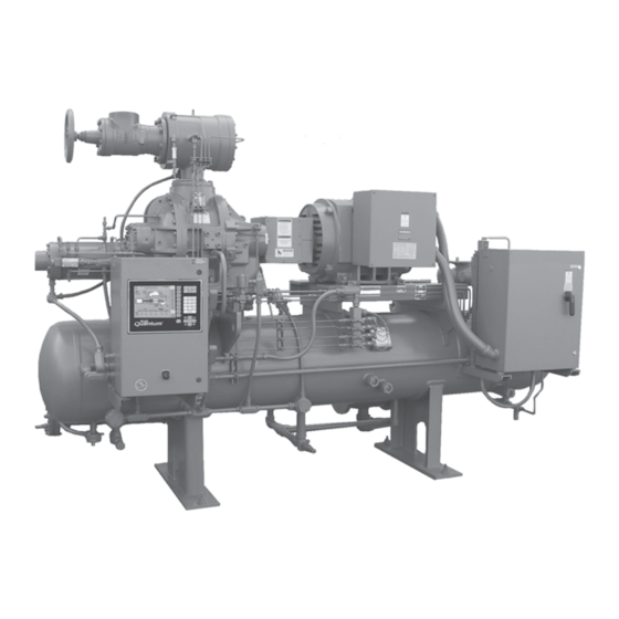
ROTARY SCREW COMPRESSOR UNITS
60 through 480
THIS MANUAL CONTAINS RIGGING, ASSEMBLY, START-UP,
AND MAINTENANCE INSTRUCTIONS. READ THOROUGHLY
BEFORE BEGINNING INSTALLATION. FAILURE TO FOLLOW THESE
INSTRUCTIONS MAY RESULT IN PERSONAL INJURY OR DEATH,
DAMAGE TO THE UNIT, OR IMPROPER OPERATION.
Please check www.johnsoncontrols.com/frick for the latest version of this publication.
Form 070.200-IOM (NOV 2011)
INSTALLATION - OPERATION - MAINTENANCE
File:
Replaces:
Dist:
RWB II
ALL REFRIGERANTS
MODELS
SERVICE MANUAL - Section 70
070-200 IOM (JAN 2009)
3, 3a, 3b, 3c
Advertisement
Table of Contents
Troubleshooting

Related Manuals for Johnson Controls Frick RWB II


Summary of Contents for Johnson Controls Frick RWB II
- Page 1 Form 070.200-IOM (NOV 2011) INSTALLATION - OPERATION - MAINTENANCE File: SERVICE MANUAL - Section 70 Replaces: 070-200 IOM (JAN 2009) Dist: 3, 3a, 3b, 3c RWB II ROTARY SCREW COMPRESSOR UNITS ALL REFRIGERANTS MODELS 60 through 480 THIS MANUAL CONTAINS RIGGING, ASSEMBLY, START-UP, AND MAINTENANCE INSTRUCTIONS.
-
Page 2: Table Of Contents
070.200-IOM (DEC 11) RWB II ROTARY SCREW COMPRESSOR UNITS Page 2 INSTALLATION - OPERATION - MAINTENANCE Contents PREFACE ................3 INITIAL START‑UP ............25 DESIGN LIMITATIONS ............3 INITIAL START‑UP PROCEDURE ........25 JOB INSPECTION .............3 NORMAL START‑UP PROCEDURE .......25 TRANSIT DAMAGE CLAIMS ..........3 MaintenanCe COMPRESSOR and UNIT IDENTIFICATION ....3 GENERAL INFORMATION ..........26... -
Page 3: Preface
RWB II ROTARY SCREW COMPRESSOR UNITS 070.200-IOM (DEC 11) GENERAL INFORMATION Page 3 PReFaCe COMPReSSOR and Unit iDentiFiCatiOn This manual has been prepared to acquaint the owner and Each compressor unit has 2 identifica tion data plates. The serviceman with the INSTALLATION, OPERATION, and compressor data plate containing compressor model and MAIN TEN ANCE procedures recommended for Frick RWB II... - Page 4 070.200-IOM (DEC 11) RWB II ROTARY SCREW COMPRESSOR UNITS Page 4 INSTALLATION GeOMetRiCaL SWePt VOLUMe taBLe Geometrical Rotor Swept Volume Compressor Diameter Rotor Speed Drive Shaft end m³/h Model ft³/ Rev m³/Rev 3550 rpm 2950 rpm TDSH 163S 1.35 4500 0.10069 0.002849 TDSH 163L...
-
Page 5: Foundation
RWB II ROTARY SCREW COMPRESSOR UNITS 070.200-IOM (DEC 11) INSTALLATION Page 5 A licensed architect should be consulted to determine the installation proper foundation requirements for any large engine or turbine drive. FOUnDatiOn aLLOWaBLe FLanGe LOaDS Each RWB ii Rotary Screw Compressor Unit is shipped nOZ. -
Page 6: Motor Mounting
070.200-IOM (DEC 11) RWB II ROTARY SCREW COMPRESSOR UNITS Page 6 INSTALLATION MOtOR MOUntinG 3. Check that the keys fit the hubs and shafts properly. CH COUPLinG – The T.B. Woods Elastomeric CH Coupling The following procedure is required only when the motor is is used in most applications up to 600 HP. - Page 7 RWB II ROTARY SCREW COMPRESSOR UNITS 070.200-IOM (DEC 11) INSTALLATION Page 7 3. Adjust the distance between hub faces as specified in the SPOt Heat tHe HUB as it may cause distortion. Heat in water, oil, or use a SOFT open flame and quickly position DBZ‑B Data Table by sliding the hubs.
-
Page 8: Coupling Alignment Procedure
070.200-IOM (DEC 11) RWB II ROTARY SCREW COMPRESSOR UNITS Page 8 INSTALLATION 3. Reassemble the coupling with the disc packs and the cen‑ ter spool. Center the coupling between the shafts and ensure that the keys are fully engaged in their keyways. Ensure that they are reassembled exactly as they were disassembled. - Page 9 RWB II ROTARY SCREW COMPRESSOR UNITS 070.200-IOM (DEC 11) INSTALLATION Page 9 PaRaLLeL aLiGnMent 6. To check parallel alignment, as shown in Figure 4, repo‑ sition dial indicator so the stem is in contact with the rim of the compressor hub, as shown in Figure 5. Check the dial indicator to be sure that the indicator stem is slightly loaded so as to allow movement in both directions.
-
Page 10: Hot Alignment Of Compressor/Motor
070.200-IOM (DEC 11) RWB II ROTARY SCREW COMPRESSOR UNITS Page 10 INSTALLATION HOt aLiGnMent OF COMPReSSOR/MOtOR of purchase. if there is any doubt due to the refrigerant, operating pressures, or temperatures, refer to Frick Pub. Hot alignments can only be made after the unit has operated 160-802 SPC for guidance. -
Page 11: Oil Filter(S)
RWB II ROTARY SCREW COMPRESSOR UNITS 070.200-IOM (DEC 11) INSTALLATION Page 11 OiL FiLteR(S) The vapor rises in the return line. The density of the refriger‑ ant liquid/vapor mixture in the return line is considerably less Use of filter elements other than than the density of the liquid in the supply line. -
Page 12: Liquid Injection Oil Cooling (Optional)
070.200-IOM (DEC 11) RWB II ROTARY SCREW COMPRESSOR UNITS Page 12 INSTALLATION SYSTEM CONDENSER VAPOR SAFETY STATIC HEAD VALVE TO OVERCOME CONDENSER THERMOSYPHON PRESSURE DROP RECEIVER LIQUID LIQUID OVERFLOW LEVEL DRAIN TO RECEIVER OPT. OIL TEMP CONTROL VALVE 6 Ft. Min. -
Page 13: Liquid Line Sizes/Receiver Volume
RWB II ROTARY SCREW COMPRESSOR UNITS 070.200-IOM (DEC 11) INSTALLATION Page 13 The level‑control method utilizes a float level control on the In some applications, the plate and shell oil cooler may be receiver to close a solenoid valve feeding the evaporator subjected to severe water conditions, including high tem‑... - Page 14 070.200-IOM (DEC 11) RWB II ROTARY SCREW COMPRESSOR UNITS Page 14 INSTALLATION Due to the tendency of the port pressure to fall with de‑ For refrigeration plants employing multiple compressors on a common economizing vessel, regardless of economizer creasing compressor capacity, a back‑pressure regulator valve (BPR) is generally required on a flash economizer type, each compressor must have a back‑pressure regulat‑...
-
Page 15: Economizer Load Balancing
VOLtaGe PROteCtiOn Johnson Controls‑Frick does not advise nor support the use of UPS power systems in front of the Quantum panel. With a UPS power system providing shutdown protection for the Quantum, the panel may not see the loss of the 3‑phase volt‑... -
Page 16: Mini Mum Burden Ratings
Mini MUM BURDen RatinGS should be considered. Contact Johnson Controls‑Frick for assistance. The following table gives the minimum CT burden ratings. -
Page 17: Control Power Regulator
RWB II ROTARY SCREW COMPRESSOR UNITS 070.200-IOM (DEC 11) INSTALLATION Page 17 COntROL POWeR ReGULatOR Compressor units that will be used in areas that suffer brown‑ outs and other significant power fluctuations can be supplied with a control power regulator. See the following illustration, Recommended Regulator Installation. -
Page 18: Operation
COMPReSSOR SHOULD neVeR Be OPeRateD in Re- VeRSe ROtatiOn aS BeaRinG DaMaGe WiLL ReSULt. The Frick RWB II Rotary Screw Compressor Unit is an inte‑ grated system consisting of six major subsystems: 1. Control Panel (See publication S90‑010 O, S90‑010 M, &... -
Page 19: Demand Pump Oil System
RWB II ROTARY SCREW COMPRESSOR UNITS 070.200-IOM (DEC 11) OPERATION Page 19 DeManD PUMP OiL SYSteM For high‑stage packages, the cold‑start valve is equipped with a large spring that creates 30 psi of pressure in the oil This system is designed to provide adequate compressor separator (above suction pressure), for lubrication of the lubrication for some high stage applications that operate with compressor. -
Page 20: Compressor Hydraulic System
070.200-IOM (DEC 11) RWB II ROTARY SCREW COMPRESSOR UNITS Page 20 OPERATION COMPReSSOR HYDRaULiC SYSteM nOte: High Stage Operation: an alternative piping ar- rangement has been provided to increase slide valve The compressor hydraulic system moves the movable slide response time during high stage operation. valve (MSV) to load and unload the compressor. -
Page 21: Compressor Oil Cooling Systems
RWB II ROTARY SCREW COMPRESSOR UNITS 070.200-IOM (DEC 11) OPERATION Page 21 COMPReSSOR OiL COOLinG SYSteMS The dual‑port system contains all the com ponents of the single‑port system with the addition of a double acting so‑ The RWB II unit can be equipped with one of several systems lenoid valve SV7 and operates as outlined. -
Page 22: Quantum™ Ez-Cool ™ Liquid Injection Adjustment Procedure
070.200-IOM (DEC 11) RWB II ROTARY SCREW COMPRESSOR UNITS Page 22 OPERATION Next, adjust the pressure regulating valve to approximately If the read value is more than the objective, use 4 to 30 psig by turning the adjustment ring inside the top of the decrease the value by the Delta. -
Page 23: Suction Check Valve
RWB II ROTARY SCREW COMPRESSOR UNITS 070.200-IOM (DEC 11) OPERATION Page 23 Figure 21 - Analog Output Calibration Figure 22 - PID Setup Integral control will increase the output in increments, Based on these descriptions set PID #1 for EZ‑Cool LIOC ™... -
Page 24: Suction Check Valve Bypass
070.200-IOM (DEC 11) RWB II ROTARY SCREW COMPRESSOR UNITS Page 24 MAINTENANCE Frick provides a power assist kit consisting of a mounted If multiple compressors are operated with a common economizer vessel, it is necessary to install a back‑pressure and wired solenoid valve and timer on all RWB II booster compressors. -
Page 25: Initial Start-Up
Page 25 initiaL StaRt-UP Initial start‑up must be performed under the super vision of a Johnson Controls‑Frick authorized start‑up representa‑ tive to prevent voiding the compressor warranty. Prior to the start‑up, the prestart check (see list in FORMS section) must be accomplish ed. -
Page 26: Maintenance
070.200-IOM (DEC 11) RWB II ROTARY SCREW COMPRESSOR UNITS Page 26 MAINTENANCE Maintenance GeneRaL inFORMatiOn 1. iF Unit iS RUnninG, PReSS StOP KeY. This section provides instructions for normal main tenance, 2. DiSCOnneCt POWeR FROM Unit BeFORe PeR- a recommended maintenance program, troubleshooting and FORMinG anY MaintenanCe. -
Page 27: General Instructions For Replacing Compressor Unit Components
RWB II ROTARY SCREW COMPRESSOR UNITS 070.200-IOM (DEC 11) MAINTENANCE Page 27 GeneRaL inStRUCtiOnS FOR RePLaCinG 2. Close outlet then inlet service valves of filter being serviced. COMPReSSOR Unit COMPOnentS. 3. Open bleed valve and purge pressure from the oil filter When replacing or repairing components which are exposed cartridge. -
Page 28: Strainer - Liquid Injection
070.200-IOM (DEC 11) RWB II ROTARY SCREW COMPRESSOR UNITS Page 28 MAINTENANCE StRaineR - LiQUiD inJeCtiOn Seat element in center of locating tabs on separator bulk head. To clean the liquid injection strainer the unit must be shut 6. Replace coalescer filter retainer and nut. Torque nut to 21 down. -
Page 29: Demand Pump Disassembly
RWB II ROTARY SCREW COMPRESSOR UNITS 070.200-IOM (DEC 11) MAINTENANCE Page 29 12. Open the suction and discharge service valves, and 7. GG, HJ, HL: Remove snap ring from shaft. See Figure 25. aS, aK, aL: Remove bearing spacer from shaft. See also the liquid injection and economizer service valves, if applicable. - Page 30 070.200-IOM (DEC 11) RWB II ROTARY SCREW COMPRESSOR UNITS Page 30 MAINTENANCE oil. Check for roughness by turning outer race by hand and sleeve, and inner diameter of mechanical seal rotary mem ber with a generous amount of refrigeration oil. Petrolatum may replace bearings if they have roughness.
-
Page 31: Troubleshooting The Demand Pump
RWB II ROTARY SCREW COMPRESSOR UNITS 070.200-IOM (DEC 11) MAINTENANCE Page 31 14. Pack double‑row ball bearing with multipurpose grease, quickly disinte grate. Using a lubricant and adding a chamfer NLGI #2. on the bushing and the mating part will help in installation. The additional precautions listed below must be followed for GG, HJ, HL: Install ball bearing into bearing housing with proper installation:... - Page 32 070.200-IOM (DEC 11) RWB II ROTARY SCREW COMPRESSOR UNITS Page 32 MAINTENANCE d. Vertical head did not consider a high specific gravity 5. Pump takes too much power a. Running too fast ‑ is correct motor speed, reducer liquid e. Line partially plugged from buildup on inside of pipe ratio, sheave size, etc.
-
Page 33: Recommended Maintenance Program
RWB II ROTARY SCREW COMPRESSOR UNITS 070.200-IOM (DEC 11) MAINTENANCE Page 33 ReCOMMenDeD MOtOR BeaRinGS MaintenanCe PROGRaM Follow the motor manufacturer’s maintenance recommenda‑ tions. See Figure 29. In order to obtain maximum compressor unit perform ance and ensure reliable operation, a regular main tenance pro‑ Make sure the motor bearings are gram should be followed. -
Page 34: Operating Log
070.200-IOM (DEC 11) RWB II ROTARY SCREW COMPRESSOR UNITS Page 34 MAINTENANCE OPeRatinG LOG The use of an operating log, as included in this manual, permits thorough analysis of the operation of a refrigeration system by those responsible for its maintenance and servicing. Continual recording of gauge pressures, temperatures, and other pertinent information, enables the observer and serviceman to be constantly familiar with the operation of the system and to recognize immediately any deviations from normal operating conditions. -
Page 35: Troubleshooting Guide
RWB II ROTARY SCREW COMPRESSOR UNITS 070.200-IOM (DEC 11) MAINTENANCE Page 35 tROUBLeSHOOtinG GUiDe 13. Problems in electrical service to compressor unit. 14. Air and moisture present in the system. Successful problem solving requires an organized ap proach to define the problem, identify the cause, and make the proper Make a list of all deviations from normal plant operation and correction. -
Page 36: Pressure Transducers - Replacement
070.200-IOM (DEC 11) RWB II ROTARY SCREW COMPRESSOR UNITS Page 36 MAINTENANCE 5. Isolate the oil pressure transducer PE‑1 from the package PReSSURe tRanSDUCeR COnVeRSiOn Data and open it to atmosphere. 200 psi 500 psi Sensor Range - PSi Range - PSiG* 6. -
Page 37: Position Potentiometer Replacement And Adjust Ment
RWB II ROTARY SCREW COMPRESSOR UNITS 070.200-IOM (DEC 11) MAINTENANCE Page 37 SV POSitiOn POtentiOMeteR Completely load the slide valve. The display at this time should indicate 100%. If the display is less than 100%, adjust RePLaCeMent anD aDJUSt Ment potentiometer POT #3 on the SBC until 100% is indicated. -
Page 38: Temperature And/Or Pressure Adjustment
Unloader piston stuck. Contact Frick Factor or Johnson Controls‑Frick for assistance. Slipper seals worn out or damaged. Contact Frick Factor or Johnson Controls‑Frick for assistance. nOte: troubleshooting the compressor is limited to identifying the probable cause. if a mechanical problem is suspected, contact... -
Page 39: The Oil Separation System
SLIDE STOP WILL NOT FUNCTION Solenoid coils may be burned out, replace. EITHER DIRECTION Solenoid service valves may be closed, open. Manually actuate solenoid. If slide stop will not move mechanical problems are indicated. Consult Frick factor or Johnson Controls‑Frick. -
Page 40: The Liquid Injection Oil Cooling System
070.200-IOM (DEC 11) RWB II ROTARY SCREW COMPRESSOR UNITS Page 40 MAINTENANCE tROUBLeSHOOtinG tHe LiQUiD inJeCtiOn OiL COOLinG SYSteM SYMPtOM PROBaBLe CaUSeS and CORReCtiOnS HIGH OIL TEMPERATURE Insufficient liquid supply, check receiver level and pressure drop at injection solenoid. Equalizer pressure too high, lower. Suction superheat too high, correct system problem. -
Page 41: Thermal Expansion Valves
RWB II ROTARY SCREW COMPRESSOR UNITS 070.200-IOM (DEC 11) MAINTENANCE Page 41 tHeRMaL eXPanSiOn VaLVeS In situations where system load conditions increase or de‑ crease over extended periods of time and the liquid injection thermal expansion valve is not adequate for the new condi‑ tions, an improvement in valve perfor mance may be achieved by increasing or decreasing discharge tube size. -
Page 42: Jordan Temperature Regulator Valve
070.200-IOM (DEC 11) RWB II ROTARY SCREW COMPRESSOR UNITS Page 42 MAINTENANCE JORDan If the hole in the valve plate is to the left and the slot in the valve disc is on the top this valve is set for Direct Acting (see teMPeRatURe ReGULatOR VaLVe Figure 37). -
Page 43: Bare Compressor Mounting
RWB II ROTARY SCREW COMPRESSOR UNITS 070.200-IOM (DEC 11) MAINTENANCE Page 43 SHUtDOWn DUe tO iMPROPeR OiL Install the valve and adjust the spring tension accordingly to maintain the predetermined oil temperature. The recom‑ PReSSURe (HiGH StaGe and BOOSteR) mended oil temperature for ammonia is 130°F. Check with Frick service for recommended oil temperatures for other the compressor must not operate with incorrect oil refrigerants. -
Page 44: P & I Diagrams
070.200-IOM (DEC 11) RWB II ROTARY SCREW COMPRESSOR UNITS Page 44 MAINTENANCE P & i DiaGRaM SHADED AREA ON 8" AND LARGER NOTE: VALVE BODY ASSY CONSISTS OF SUCTION STOP VALVES ONLY SUCTION STRAINER AND CHECK VALVE. SUCTION GAS TO COMPRESSOR PDALL PALL STR-4... - Page 45 RWB II ROTARY SCREW COMPRESSOR UNITS 070.200-IOM (DEC 11) MAINTENANCE Page 45 P & i DiaGRaM - OPtiOnaL DUaL OiL FiLteRS, DeManD OiL PUMP, tHeRMaL COntROL VaLVe SEPARATOR TO COMPRESSOR PALL TAHH OPTIONAL CV-2 DEMAND STR-2 OIL PUMP PM-1 CV-1 PDAH OF-1 OPTIONAL...
- Page 46 070.200-IOM (DEC 11) RWB II ROTARY SCREW COMPRESSOR UNITS Page 46 MAINTENANCE P & i DiaGRaM, LiQUiD inJeCtiOn – SinGLe PORt P & i DiaGRaM, LiQUiD inJeCtiOn – DUaL PORt...
- Page 47 RWB II ROTARY SCREW COMPRESSOR UNITS 070.200-IOM (DEC 11) MAINTENANCE Page 47 P & i DiaGRaM, LiQUiD inJeCtiOn – BOOSteR...
-
Page 48: Proper Installation Of Electronic Equipment In An Industrial Environment
070.200-IOM (DEC 11) RWB II ROTARY SCREW COMPRESSOR UNITS Page 48 PROPER INSTALLATION OF ELECTRONIC EQUIPMENT PROPeR inStaLLatiOn OF eLeCtROniC eQUiPMent in an inDUStRiaL enViROnMent In today’s refrigeration plants, electronic controls have found loaded to its maximum capacity, the voltage dips are much their way into almost every aspect of refrigeration control. - Page 49 This worked for the earlier relay systems, but Johnson Controls‑Frick requires that the ground conductor it is in no way acceptable for electronic control equipment.
- Page 50 480 volt circuit will be induced onto the 120 volt circuit causing functional problems Johnson Controls‑Frick conduit requirements: with the electronic control panel. Metallic dividers must be • For variable frequency drives (VFDs) of any type, threaded used in wire way systems (conduit trays) to separate unlike metallic or threaded PVC‑coated metallic is required...
- Page 51 RWB II ROTARY SCREW COMPRESSOR UNITS 070.200-IOM (DEC 11) PROPER INSTALLATION OF ELECTRONIC EQUIPMENT Page 51 Do not drill into an electronic control panel to locate conduit if the electronic control panel has a starter built into the same panel, be sure to run the higher voltage wires where connections.
- Page 52 UPS POWeR anD QUantUM PaneLS The use of communications such as serial and ethernet Johnson Controls, Inc. does not advise nor support the in industrial environments are commonplace. The proper use of uninterrupted power supply systems for use with the installation of these networks is as important to the proper Quantum panel.
-
Page 53: Forms
RWB II PLUS ROTARY SCREW COMPRESSOR UNITS 070.200-IOM (DEC 11) FORMS Page 53 OPeRatinG LOG SHeet... - Page 54 070.200-IOM (DEC 11) RWB II PLUS ROTARY SCREW COMPRESSOR UNITS Page 54 FORMS RWB II COMPRESSOR PRESTART CHECKLIST The following items MUST be checked and completed by the installer prior to the arrival of the Frick Field Service Supervisor. Details on the checklist can be found in this manual. Certain items on this checklist will be reverified by the Frick Field Service Supervisor prior to the actual start-up.
- Page 55 RWB II PLUS ROTARY SCREW COMPRESSOR UNITS 070.200-IOM (DEC 11) FORMS Page 55 Start-up Report Frick Order No: ________________________ Sold To: _______________________________________ Contact Name:__________________________ Date:__________________ End User: ______________________________________ Contact Name:__________________________ Phone:__________________ End User Address: ______________________________________________________________________ Fax No:__________________ City, State, Zip: _________________________________ Start-up Representative _________________ Unit General Information Unit Model # ___________________________________________ Customer Package Identification # _________________________ Compressor Serial # _ ____________________________________ Separator National Board # _ _______________________________ Unit Serial # _ ___________________________________________ Oil Cooler National Board # _______________________________ Evaporator National Board # _ ______ Serial # _______________ Condenser National Board # ________ Serial # _______________ Oil Pot National Board # _________________________________ H.P. Receiver National Board # _ _____...
- Page 56 070.200-IOM (DEC 11) RWB II PLUS ROTARY SCREW COMPRESSOR UNITS Page 56 FORMS Page 2 Unit Serial # _ ____________________________ Frick Order No: ____________________________ Capacity Control Setpoints Mode __________________ Mode __________________ Setpoint ________ Regulation Safeties Setpoint ________ Regulation Safeties High Low Load Inhibit ________ High Low Load Inhibit _________ Prop. Band ________ ________ Force Unload _ _______ Prop. Band...
- Page 57 RWB II PLUS ROTARY SCREW COMPRESSOR UNITS 070.200-IOM (DEC 11) FORMS Page 57 Page 3 Unit Serial # _ ____________________________ Frick Order No: ____________________________ Compressor Motor Setpoints and Information Manufacturer ___________ Motor Name Plate Motor Amps ___________ Maximum Drive Output ___ % Frame Size ______________ Volts ___________ Minimum Drive Output ___ % H.P. ____________________ Service Factor ___________ Remote Control RPM ___________________ Horsepower ___________ Rate Of Increase ________ % Delay ____ Sec Serial # _________________...
- Page 58 070.200-IOM (DEC 11) RWB II PLUS ROTARY SCREW COMPRESSOR UNITS Page 58 FORMS Page 4 Unit Serial # _ _______________ Frick Order No: __________________________________________ Communications Compressor ID ___ Comm 1 Comm 2 Comm 3 Baud Rate _ ________ Baud Rate __________ Baud Rate _ __________ Data Bits _________ Data Bits _ ___________ Data Bits _ ___________ Stop Bits _________ Stop Bits ___________...
- Page 59 RWB II PLUS ROTARY SCREW COMPRESSOR UNITS 070.200-IOM (DEC 11) FORMS Page 59 ViBRatiOn Data SHeet Date: ______________________________________ Sales Order Number: _____________________________ End User: ___________________________________ Installing Contractor: _____________________________ Address: ______________________________________ Service Technician: ______________________________ Final Hot alignment Equipment ID (As in Microlog): __________________ Compressor Model Number: _______________________ Compressor Serial Number: _______________________...
- Page 60 Form 070.200-IoM (2011-12) Johnson Controls Supersedes: 070-200 IOM (2009-01) 100 CV Avenue Subject to change without notice Waynesboro, PA 17268-1206 USA Published in USA • GUI 1C Phone: 717-762-2121 • FAX: 717-762-8624 www.johnsoncontrols.com/frick © 2011 Johnson Controls Inc. - ALL RIGHTS RESERVED...
Need help?
Do you have a question about the Frick RWB II and is the answer not in the manual?
Questions and answers