Table of Contents
Advertisement
Quick Links
700 (60 Hz) / 572 (50 Hz) Horsepower
912 (60 Hz) / 752 (50 Hz) Horsepower
THIS MANUAL CONTAINS RIGGING, ASSEMBLY, START-UP,
AND MAINTENANCE INSTRUCTIONS. READ THOROUGHLY
BEFORE BEGINNING INSTALLATION. FAILURE TO FOLLOW THESE
INSTRUCTIONS MAY RESULT IN PERSONAL INJURY OR DEATH,
DAMAGE TO THE UNIT, OR IMPROPER OPERATION.
Please check www.jci.com/frick for the latest version of this publication.
Form 100.210-IOM (FEB 2015)
INSTALLATION - OPERATION - MAINTENANCE
File:
SERVICE MANUAL - Section 100
Replaces:
100.210-IOM (SEP 2012)
Dist:
3, 3a, 3b, 3c
Advertisement
Table of Contents

Related Manuals for Johnson Controls Frick 700


Summary of Contents for Johnson Controls Frick 700
- Page 1 Form 100.210-IOM (FEB 2015) INSTALLATION - OPERATION - MAINTENANCE File: SERVICE MANUAL - Section 100 Replaces: 100.210-IOM (SEP 2012) Dist: 3, 3a, 3b, 3c 700 (60 Hz) / 572 (50 Hz) Horsepower 912 (60 Hz) / 752 (50 Hz) Horsepower THIS MANUAL CONTAINS RIGGING, ASSEMBLY, START-UP, AND MAINTENANCE INSTRUCTIONS.
-
Page 2: Table Of Contents
100.210-IOM (FEB 2015) VYPER VARIABLE SPEED DRIVE ™ Page 2 INSTALLATION - OPERATION - MAINTENANCE TABLE OF CONTENTS VYPER ™ .PREINSTALLATION.SITE.ChECKLIST........ 29 PREFACE VYPER .POWER.AND.CONTROL.ENTRY.LOCATIONS....30 ™ INTRODUCTION................4 EXTERNAL.POWER.AND.CONTROL.WIRING......... 31 JOB.INSPECTION................4 INPUT.POWER.CONNECTION............. 31 TRANSIT.DAMAGE.CLAIMS............4 OUTPUT.POWER.CONNECTION.(REMOTE.MOUNT)....32 UNIT.IDENTIFICATION. - Page 3 VYPER VARIABLE SPEED DRIVE 100.210-IOM (FEB 2015) ™ INSTALLATION - OPERATION - MAINTENANCE Page 3 LIST OF FIGURES Figure.1.–.Vyper .Data.Plate............4 Figure.38.-.Topping.Off.the.Coolant.Supply......... 39 ™ Figure.2A.-.Vyper ™ .Elementary.Wiring.Diagram......9 Figure.39.-.Installing.the.Cooling.System.Pipe.Plug..... 39 Figure.2B.-.Vyper .Elementary.Wiring.Diagram......10 Figure.40.-.VSD.Logic.Board.Connection.J2........ 39 ™ Figure.3.-.VSD.Input.Current.Without.harmonic.Filter....12 Figure.41.-.Quantum ™...
-
Page 4: Introduction
100.210-IOM (FEB 2015) VYPER VARIABLE SPEED DRIVE ™ Page 4 INSTALLATION - OPERATION - MAINTENANCE PREFACE Each. Vyper . has. a. unit. identification. label. located. on. the. ™ right.side.of.the.cabinet..The.data.plate.contains.the.Frick. . Part.Number,.the.unique.Serial.Number,.and.the.basic.Model. INTRODUCTION Number.for.the.unit..In.addition,.the.data.label.also.has.elec- This.manual.has.been.prepared.to.acquaint.the.owner.and. trical.information.pertinent.to.the.individual.unit. service.personnel.with.the.INSTALLATION, OPERATION, and NOTICE MAINTENANCE. procedures. as. recommended. by. Johnson. Controls-Frick.for.the.Frick.Vyper .Variable.Speed.Drive.unit. -
Page 5: Model.descriptions
VYPER VARIABLE SPEED DRIVE 100.210-IOM (FEB 2015) ™ INSTALLATION - OPERATION - MAINTENANCE Page 5 MODEL DESCRIPTIONS These.tables.provide.the.model.number,.Frick.part.number.and.basic.description.of.each.Vyper Drive.covered.in.this.manual. ™. Model No. Frick P/N Description VYE_PH_S-46 720C0168G01 700 HP, Water Cooled, 460 Volts, Package Mount, 3 HP Oil Pump VYE_PH_M-46 720C0168G02 700 HP, Water Cooled, 460 Volts, Package Mount, 5 HP Oil Pump VYE_PH_L-46... -
Page 6: Vyper.pre-Installation.site.check.list
100.210-IOM (FEB 2015) VYPER VARIABLE SPEED DRIVE ™ Page 6 INSTALLATION - OPERATION - MAINTENANCE Read This First Vyper Pre-Installation and Pre-Operation Checklist The.following.items.MUST.be.checked.and.completed.by.the.installer.prior.to.the.arrival.of.the.Frick.Field.Service.Supervisor.. Details.on.the.checklist.can.be.found.in.this.manual..Certain.items.on.this.checklist.will.be.re-verified.by.the.Frick.Field.Service. Supervisor.prior.to.the.actual.start-up. Vyper Pre-Installation Site Check List Before.attempting.to.install.a.Vyper.Drive.system,.please.perform.a.site.inspection.to.assure.that.the.following.requirements.are. met..(Where.Applicable) --.Verify.that.the.coolant.(water.or.glycol).is.available.for.the.Vyper.heat.exchanger.connections..hard-pipe.the.coolant. supply.in.accordance.to.all.local.and.national.piping.codes..Sufficient.coolant.flow.and.temperature.levels.must.be. available.to.the.Vyper.VSD.at.installation..When.hard-piping.the.coolant.supply,.take.into.consideration.that.room.is. required.in.order.to.add.coolant.to.the.system. --.Verify.that.the.compressor.package.temperature.sensors.are.RFI.suppression.type.(639A0151G01).. --.Incoming.power.cables.must.enter.through.the.access.plate.supplied.on.the.top.left.side.of.the.unit..This.access.plate. MUST.BE.removed,.entry.holes.made.in.the.plate,.and.then.reinstalled..Power.cables.MUST.BE.in.accordance.with. local.and.national.electrical.codes.and.current.safety.standards..See.“External.Power.And.Control.Wiring”.in.the. -
Page 7: Pre-Startup.inspection
VYPER VARIABLE SPEED DRIVE 100.210-IOM (FEB 2015) ™ INSTALLATION - OPERATION - MAINTENANCE Page 7 --.Apply.power.to.the.Vyper.Drive.system.. A:. Confirm.dipswitches.on.the.Vyper.Logic.Board.are.properly.set..Refer.to.“VSD.Logic.Board.Setup”.in.the.OPERATION. section.of.this.manual. B:. Verify.no.problems.exist.with.the.unit.power.supply.connections. C:. Verify.no.problems.exist.with.the.boot-up.of.the.Quantum LX.panel.and.control.system. ™ D:. Set.the.FLA.ratings.on.the.Vyper.Logic.Board.as.per.job.site.requirements. E:. Set.up.the.Quantum ™ LX.panel.in.accordance.with.job.site.requirements..Refer.to.“Quantum ™ LX.Panel.Setup”.in.the. OPERATION.section.of.this.manual. F:. Confirm.operation.of.internal.cooling.fans. G:. Confirm.operation.of.the.coolant.pump. h:. Confirm.operation.of.the.Vyper.motorized.coolant.temperature.control.mixing.valve.. I:. -
Page 8: Vyper System Overview
100.210-IOM (FEB 2015) VYPER VARIABLE SPEED DRIVE ™ Page 8 INSTALLATION - OPERATION - MAINTENANCE of.the.voltage.between.the.series.connected.capacitors.and. VYPER SYSTEM OVERVIEW ™ to.provide.a.discharge.means.for.the.capacitor.bank.when. the.VSD.is.powered.off,.“bleeder”.resistors.(3RES.and.4RES). VYPER COMPONENT DESCRIPTION ™ are.connected.across.the.capacitor.banks. The DC to AC Inverter. section. of. the. VSD. (See. Fig.. 2),. The. Frick. Vyper . -
Page 9: Figure 2A - Vyper ™ Elementary Wiring Diagram
VYPER VARIABLE SPEED DRIVE 100.210-IOM (FEB 2015) ™ INSTALLATION - OPERATION - MAINTENANCE Page 9 NOTE: Drawings for specific units can be found in the door of the Vyper Drive or check with Frick Engineering department. Figure 2A - Vyper Elementary Wiring Diagram ™... -
Page 10: Figure 2B - Vyper ™ Elementary Wiring Diagram
100.210-IOM (FEB 2015) VYPER VARIABLE SPEED DRIVE ™ Page 10 INSTALLATION - OPERATION - MAINTENANCE NOTE: Drawings for specific units can be found in the door of the Vyper Drive or check with Frick Engineering department. Figure 2B - Vyper Elementary Wiring Diagram ™... -
Page 11: Harmonic.filter
VYPER VARIABLE SPEED DRIVE 100.210-IOM (FEB 2015) ™ INSTALLATION - OPERATION - MAINTENANCE Page 11 HARMONIC FILTER the. filter. to. “work. against”.. The. inductor. effectively. limits. the.rate.of.change.of.current.at.the.input.to.the.filter.to.a. The.VSD.system.may.include.an.harmonic.filter.designed.to. reasonable.level. meet.the.IEEE.Std.519.-1992,.“IEEE.Recommended.Practices. The IGBT Phase Bank Assembly. is. the. most. complicated. and.Requirements.for.harmonic.Control.in.Electrical.Power. power.component.in.the.harmonic.filter..The.purpose.of.the. -
Page 12: Figure.3.-.Vsd.input.current.without.harmonic.filter
100.210-IOM (FEB 2015) VYPER VARIABLE SPEED DRIVE ™ Page 12 INSTALLATION - OPERATION - MAINTENANCE Figure 3 - VSD Input Current Without Harmonic Filter Figure 4 - VSD Input Current With Harmonic Filter... -
Page 13: Figure.5A.-.Harmonic.filter.elementary.wiring.diagram
VYPER VARIABLE SPEED DRIVE 100.210-IOM (FEB 2015) ™ INSTALLATION - OPERATION - MAINTENANCE Page 13 NOTE: Drawings for specific units can be found in the door of the Vyper Drive or Figure 5A - Harmonic Filter Elementary Wiring Diagram check with Frick Engineering department. -
Page 14: Figure.5B.-.Harmonic.filter.elementary.wiring.diagram
100.210-IOM (FEB 2015) VYPER VARIABLE SPEED DRIVE ™ Page 14 INSTALLATION - OPERATION - MAINTENANCE NOTE: Drawings for specific units can be found in the door of the Vyper Drive or Figure 5B - Harmonic Filter Elementary Wiring Diagram check with Frick Engineering department. -
Page 15: General.operation.description
VYPER VARIABLE SPEED DRIVE 100.210-IOM (FEB 2015) ™ INSTALLATION - OPERATION - MAINTENANCE Page 15 GENERAL OPERATION DESCRIPTION In.addition,.the.drive.is.capable.of.operating.without.a.load. for.ease.of.service..Refer.to.Table.4.for.current.limits. The.Vyper ™ .serves.as.the.motor.starter.and.capacity.control. for.a.Frick.screw.compressor..The.Vyper .controls.capacity.by. TABlE 4 – UnIT CUrrEnT lImITS ™ reducing.compressor.speed.and.optimizing.the.compressor. Freq Voltage RMS current LRA max efficiency.at.all.loads. 912 HP 60 Hz 460V... - Page 16 100.210-IOM (FEB 2015) VYPER VARIABLE SPEED DRIVE ™ Page 16 INSTALLATION - OPERATION - MAINTENANCE NOTES...
-
Page 17: Installation
VYPER VARIABLE SPEED DRIVE 100.210-IOM (FEB 2015) ™ INSTALLATION Page 17 does.not.require.an.additional.dV/dt.filter.between.the.VFD. Installation cabinet.and.the.motor.. RIGGING AND HANDLING Figure.6.shows.Vyper .cabinet.mounted.on.a.Frick.RWF.II. ™ refrigeration.package..Individual.systems.configurations.will. Each.Vyper .Variable.Speed.Drive.unit.is.shipped.mounted.on. ™ vary.according.to.model.and.horsepower.sizes.selected. a.wooden.skid.or.mounted.to.the.refrigeration.package..All. shipping.materials.must.be.removed.prior.to.unit.installation. On.package.mounted.units,.the.Vyper .cabinet.is.mounted. ™ on.a.rectangular.welded.steel.channel,.which.provides.both. The.Vyper .cabinet.unit.is.best.moved.via.lifting.lugs.on.the. ™ an.attachment.point.for.the.cabinet’s.side.brackets.and.also. top.sides.of.the.cabinet..Caution.must.be.used.to.not.damage. helps.to.maintain.the.rigidity.of.the.cabinet.during.service.. . the.pump.or.peripheral.equipment.on.the.rear.of.the.cabinet.. . The.channel.assembly./.VSD.cabinet.is.mounted.on.two.ex- Never.move.the.unit.by.pushing.against.the.Vyper .cabinet. -
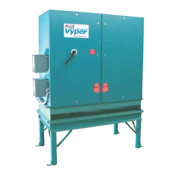
Page 18: Figure.7.-.Vyper™.Cabinet.and.stand
100.210-IOM (FEB 2015) VYPER VARIABLE SPEED DRIVE ™ Page 18 INSTALLATION Figure 7 - Vyper™ Cabinet and Stand... -
Page 19: Environment
VYPER VARIABLE SPEED DRIVE 100.210-IOM (FEB 2015) ™ INSTALLATION Page 19 the.foundation.must.be.able.to.support.the.weight.of.the. VYPER COOLING CONFIGURATION ™ cabinet.and.base..In.addition,.the.Vyper .cabinet.must.be. ™ The. Frick. Vyper ™ . is. internally. cooled. with. a. factory. cali- located.so.that.no.more.than.fifty.(50).feet.(15.meters).of. brated. liquid. cooling. circuit. that. offers. many. advantages. motor.wiring.length.is.needed.between.the.VSD.cabinet.and. -
Page 20: Coolant.temperature.limits
100.210-IOM (FEB 2015) VYPER VARIABLE SPEED DRIVE ™ Page 20 INSTALLATION COOLANT TEMPERATURE LIMITS •. An.upstream.strainer.is.recommended.to.stop.particulate. matter.from.entering.the.heat.exchanger..The.strainer. Liquid.supply.cooling.temperature.limits.vary.between.Water. should.be.cleaned.several.times.during.the.first.twenty- and.Glycol.cooled.units..The.required.coolant.flow.rate.is. four.hours.of.operation. based.on.the.maximum.temperature.of.the.coolant.type.to. •. Refer.to.the.charts.in.Figures.8.and.9.for.minimum.flow. be.used. rates.. TABlE 8 – EnTErIng CoolAnT TEmPErATUrE lImITS WATER RECOMMENDATIONS Entering Coolant Temperature Limits •. Johnson. -
Page 21: Heat.exchanger.pres
VYPER VARIABLE SPEED DRIVE 100.210-IOM (FEB 2015) ™ INSTALLATION Page 21 Figure 9 - minimum Flow rates - glyCol HEAT ExCHANGER PRESSURE DROP 912/752 & 700/572 Models In.order.to.adequately.size.piping.and.booster.pump.require- designers.with.pressure.drop.reference.for.different.mixtures. ments,. the. pressure. drop. of. the. coolant. across. the. heat. of.propylene.glycol.and.water.. exchanger.must.be.known..Figure.10.provides.installation. -
Page 22: Figure.11.-.Vyper ™ .P&I.diagram.-.Noneconomized
100.210-IOM (FEB 2015) VYPER VARIABLE SPEED DRIVE ™ Page 22 INSTALLATION ™ Figure 11 - liquid Cooled Vyper P&I Diagram - noneconomized ™ Figure 12 - liquid Cooled Vyper P&I Diagram - Economized... -
Page 23: Proper.installation.of.electronic.equipment
VYPER VARIABLE SPEED DRIVE 100.210-IOM (FEB 2015) ™ INSTALLATION Page 23 PROPER INSTALLATION OF ELECTRONIC EQUIPMENT IN AN INDUSTRIAL ENVIRONMENT In. today’s. refrigeration. plants,. electronic. controls. have. a.complete.reset.of.the.control.system..If.the.wire.is.loaded. found. their. way. into. almost. every. aspect. of. refrigeration. to.its.maximum.capacity,.the.voltage.dips.are.much.larger,. control.. . Electronic. controls. have. brought. to. the. industry. and.the.potential.of.a.malfunction.is.very.high..If.the.wire. -
Page 24: Grounding
100.210-IOM (FEB 2015) VYPER VARIABLE SPEED DRIVE ™ Page 24 INSTALLATION GROUNDING NEC.size.ratings.are.for.safety.purposes.and.not.necessarily. for.adequate.relaying.of.noise.(EMI).to.earth.ground.to.avoid. Grounding.is.the.most.important.factor.for.successful.opera- possible. interference. with. sensitive. equipment.. Therefore. tion.and.is.typically.the.most.overlooked...The.NEC.states.that. sizing.this.conductor.1.–.2.sizes.larger.than.required.by.code. control.equipment.may.be.grounded.by.using.the.rigid.conduit. will.provide.better.transfer.of.this.noise.. as.a.conductor..This.worked.for.the.earlier.relay.systems,.but. Johnson.Controls-Frick .requires.that.the.ground.conductor. it.is.in.no.way.acceptable.for.electronic.control.equipment.. ® meet.the.following::. Conduit.is.made.of.steel.and.is.a.poor.conductor.relative. to.an.insulated.stranded.copper.wire..Electronic.equipment. •. Stranded.Copper reacts.to.very.small.currents.and.must.have.a.proper.ground. •. Insulated in. order. to. operate. properly;. therefore,. stranded. copper. •. -
Page 25: Conduit
VYPER VARIABLE SPEED DRIVE 100.210-IOM (FEB 2015) ™ INSTALLATION Page 25 •. Due.to.the.level.of.EMI.that.can.be.induced.onto.lower. ground.to.the.3-phase.supply.transformer.(plant)..This.will. require. that. the. 3-phase. ground. and. the. control. power. voltage.lines.when.running.multiple.feeders.in.a.trench,. ground.be.electrically.isolated.except.for.the.connection.at. control.power,.communications,.analog,.or.signal.wiring. the.plant.supply.transformer.. cannot.be.run.in.trenches.that.house.multiple.conduits/ electrical.ducts.carrying.3-phase.power.to.starters/vfd. This. style. of. grounding. should. steer. the. noise. (EMI/RFI). or.motors.. to.earth.ground,.reducing.the.potential.for.it.to.affect.the. •. -
Page 26: Communications
100.210-IOM (FEB 2015) VYPER VARIABLE SPEED DRIVE ™ Page 26 INSTALLATION These.holes.are.strategically.placed.so.that.the.field.wiring. If the electronic control panel has a starter built into the does.not.interfere.with.the.electronics.in.the.panel..Never. same panel, be sure to run the higher voltage wires where allow.field.wiring.to.come.in.close.proximity.with.the.con- indicated by the manufacturer.. EMI. from. the. wires. can. troller.boards.since.this.will.almost.always.cause.problems. -
Page 27: Ups.power.and.quantum™.Panels
VYPER VARIABLE SPEED DRIVE 100.210-IOM (FEB 2015) ™ INSTALLATION Page 27 It.is.important.to.carefully.consider.the.type.of.cable.to.be. With. the. starter. contactor. still. energized,. the. compres- used..Just.because.a.cable.has.the.proper.number.of.conduc- sor. auxiliary. will. continue. to. feed. an. “okay”. signal. to. the. tors.and.is.shielded.does.not.mean.it.is.an.acceptable.cable.. Quantum .panel..This.may.allow.the.motor.to.be.subjected. ™ Johnson.Controls,.Inc..recommends.the.use.of.Belden.#9829. to.the.fault.condition.on.the.3-phase.bus. for.RS-422.communications.and.Belden.#.9841.for.RS-485. A. couple. of. fault. scenarios. are:. 1.. The. 3-phase. bus. has. up. -
Page 28: Electrical.wiring.conduit
100.210-IOM (FEB 2015) VYPER VARIABLE SPEED DRIVE ™ Page 28 INSTALLATION TABlE 9 – DIgITAl ConTrol SIgnAl WIrE rECommEn- TABlE 10 – rECommEnDED TrAnSFormEr SIzES DATIonS Impedance Weight (lb) 5%-6% 1100 Recommended Digital Signal Wire 5%-6% 1470 Unshielded Per.US.NEC.or.applicable.electrical.code. 5%-6% 1750 Shielded 18AWG.(0.750.mm... -
Page 29: Interference With Electronic Equipment
VYPER VARIABLE SPEED DRIVE 100.210-IOM (FEB 2015) ™ INSTALLATION Page 29 INTERFERENCE WITH ELECTRONIC INTERFACING ELECTRICAL EQUIPMENT EQUIPMENT There.are.many.low-voltage.DC.signals.in.the.Vyper™.that. may.be.picked.up.from.other.electrical.devices.or.wiring.in. RFI. /. EMI. are. acronyms. for. Radio. Frequency. Interference. the.vicinity.of.the.Vyper™.electronic.controls..Use.the.fol- and. Electro-Magnetic. Interference.. Any. electronic. device. lowing.guidelines.to.prevent.the.Vyper™.electronic.controls. that.switches.currents.at.high.speed.is.capable.of.generat- from.picking.up.low-voltage.DC.signals.and.possibly.cause. ing.RFI.and.EMI..Some.typical.sources.are.computers,.light. injury.or.damage.to.the.electronic.controls: dimmers,.and.motor.speed.controls..RFI.refers.to.electrical. -
Page 30: Vyper ™ .Power.and.control.entry.locations
100.210-IOM (FEB 2015) VYPER VARIABLE SPEED DRIVE ™ Page 30 INSTALLATION VYPER POWER AND CONTROL ENTRY LOCATIONS ™ Vyper.drives.provide.a.removable.plate.on.the.top.left.of.the. Under.no.circumstances.is.it.acceptable.to.bring.power.into. cabinet.that.designates.the.point.of.entry.for.the.incoming. or.take.power.out.of.a.Vyper.at.any.other.point. power..This.is.the.only.acceptable.point.of.entry.for.power. It.is.possible.to.come.up.through.the.floor,.alongside.of.the. into. a. Vyper. drive.. This. plate. must. be. removed. for. the. Vyper,.then.turn.in.and.down.into.the.drive..All.NEC.codes. proper.sized.holes.to.be.punched.and.then.reinstalled..For. relative.to.conductor.size.and.bend.radius.must.be.followed. remote.mounted.cabinets,.the.power.exits.through.the.top. of.a.separate.motor.connection.box..The.holes.on.this.box. can.be.punched.in.place.since.there.is.no.chance.for.metal. -
Page 31: External.power.and.control.wiring
VYPER VARIABLE SPEED DRIVE 100.210-IOM (FEB 2015) ™ INSTALLATION Page 31 ExTERNAL POWER AND CONTROL WIRING DANGER Shock Hazard! Before beginning service, use proper lock-out/tag-out procedures to disconnect all power supplies related to this equipment. Verify all power is removed from the supply leads. Death or severe personal injury will occur if proper care is not taken. -
Page 32: Output.power.connection.(Remote.mount)
100.210-IOM (FEB 2015) VYPER VARIABLE SPEED DRIVE ™ Page 32 INSTALLATION OUTPUT POWER CONNECTION (REMOTE MOUNT) The.output.power.attachment.lugs.are.labeled.“T1”,.“T2”,.and. “T3”.are.located.on.the.inside.right.rear.wall.of.the.Vyper ™ Prepare.the.output.power.leads.by.stripping.0.5.to.1.0.inch. cabinet.(See.Figure.23). (13.to.25.mm).of.insulation.from.the.ends.of.the.power.leads. (See.Figure.20). The.power.wiring.emerges.from.the.rectangular.cutout.on. the.rear.wall.of.the.Vyper ™ .cabinet.(See.Figure.23)..These. The.motor.leads.must.be.brought.in.from.the.top.of.the.unit.. connections.are.made.in.the.factory.and.will.be.pretested. Carefully. remove. the. panel,. which. covers. the. motor. lead. before. shipment.. For. proper. installation,. connect. an. ap- entry. -
Page 33: Vyper Wiring.and.wiring.diagrams
VYPER VARIABLE SPEED DRIVE 100.210-IOM (FEB 2015) ™ INSTALLATION Page 33 ™ Figure 24 - Vyper Starter, motor, Blower, and quantum Wiring VYPER ™ WIRING AND WIRING DIAGRAMS QUANTUM Lx COMMUNICATIONS WIRING ™ Figure.25.shows.the.junction.points.for.the.Quantum ™ LX.panel. Figures.24.through.29.provide.the.wiring.terminations.for.the. control.wiring.into.the.Vyper ™ .cabinet..This.wiring.location. Frick.Vyper Drive..These.drawings.illustrate.the.necessary. -
Page 34: Figure.26.-.Analog.board.wiring
100.210-IOM (FEB 2015) VYPER VARIABLE SPEED DRIVE ™ Page 34 INSTALLATION THIS WIRING MAY GO TO ANA 1 OR 2 ANALOG BOARD NOT NECESSARILY MOUNTED IN THIS POSITION OV OR COM ñ CABLE #29 TE-6 ICTD VYPER COOLING TEMP SENSOR ANALOG BELDEN #8762 OR EQUAL BOARD... -
Page 35: Figure.28.-.Thermistor.motor.protection.wiring
VYPER VARIABLE SPEED DRIVE 100.210-IOM (FEB 2015) ™ INSTALLATION Page 35 Figure 28 - Thermistor motor Protection Wiring Figure 29 - rTD motor Protection Wiring... -
Page 36: Vyper Pre-Operation Site Checklist
100.210-IOM (FEB 2015) VYPER VARIABLE SPEED DRIVE ™ Page 36 INSTALLATION VYPER PRE-OPERATION SITE CHECKLIST ™ Prior.to.Quantum ™ .LX.setup.and.starting.operation.of.the.Vyper ™ .Drive.system,.review.the.following.checklist.to.ensure.all.instal- lation.requirements.are.met..(Where.Applicable) . � ��������������������������Verify.that.the.primary.water.or.glycol.coolant.supply.is.connected.to.the.heat.exchanger.at.the.recom- mended.flow.and.temperature.recommendations. . � ��������������������������Drain.the.shipping.coolant.from.Vyper .and.properly.dispose..Replace.with.running.coolant.(pink).and.purge. ™ air.from.the.cooling.system...Refer.to.the.“Adding.and.Replacing.Coolant”.portion.of.this.manual. . � ��������������������������Verify.that.the.package.temperature.sensors.are.RFI.suppression.type.(639A0151G01) . � ��������������������������Environment: a.. Cleanliness...Keep.construction.debris.out.of.the.cabinet b.. -
Page 37: Blower.motor.rotation
VYPER VARIABLE SPEED DRIVE 100.210-IOM (FEB 2015) ™ INSTALLATION Page 37 BLOWER MOTOR ROTATION COOLANT CONTAMINATION AND PROPERTIES The.Blower.Motor.rotation.is.marked.on.the.blower.assembly. and.is.to.be.such.that.the.blower.draws.into.the.assemly. Drive.coolant.comes.packaged.in.1-gallon.containers. through.the.screen.and.pushes.down.and.through.the.motor.. The.coolant.is.premixed.and.should.not.be.diluted. See.Figures.30.and.30a. The.drive.coolant.is.pink.color.but.may.become.clear.over. time..Although.the.coolant.may.become.clear,.the.nitrate. inhibitor.is.still.effective. The. coolant. volume. varies. by. the. size. of. the. drive.. The. 700.hP.drive.requires.3.gallons.and.the.912.hP.requires.4. gallons. Coolant.part.number.is.639A0211h36. -
Page 38: Adding.and.replacing.coolant
100.210-IOM (FEB 2015) VYPER VARIABLE SPEED DRIVE ™ Page 38 INSTALLATION ADDING AND REPLACING COOLANT Step 1: (See. Figure. 33). Disconnect. power. from. the. VSD.. . Remove.the.pipe.plug.from.the.top.of.the.exit.manifold.with. CAUTION an.adjustable.wrench...This.allows.air.to.enter.the.system. and.displace.the.fluid.during.draining. Irritant! Coolant is an irritant. Always wear eye protec- tion when servicing the Vyper ™... -
Page 39: Figure.36.-.Refilling.the.cooling.system
VYPER VARIABLE SPEED DRIVE 100.210-IOM (FEB 2015) ™ INSTALLATION Page 39 Step 4:.(Figure.36).Close.the.drain.valve.and.refill.the.cooling. Step 7: (Figure.39).Replace.and.tighten.the.plug.on.the.top. system.with.the.new.coolant. of.the.manifold.using.an.adjustable.wrench. Figure 39 - Installing the Cooling System Pipe Plug Step 8: (Figure.40).Insert.plug.J2.into.the.logic.board.to.stop. Figure 36 - refilling the Cooling System the.coolant.pump. Step 5:.(Figure.37).Apply.power.to.the.VSD.unit.and.locate. the.Logic.Board.found.on.the.inside.of.the.cabinet..Unplug. - Page 40 100.210-IOM (FEB 2015) VYPER VARIABLE SPEED DRIVE ™ Page 40 INSTALLATION - OPERATION - MAINTENANCE NOTES...
-
Page 41: Operation
VYPER VARIABLE SPEED DRIVE 100.210-IOM (FEB 2015) ™ OPERATION Page 41 When. the. slide. valve. reaches. the. capacity. control. “Slide. OPERATION Valve”.setpoint,.the.motor.speed.can.then.increase..At.this,. point.the.slide.valve.and.motor.speed.continue.to.increase. QUANTUM Lx CONTROL PANEL ™ independently.of.one.another.until.the.capacity.requirement. This.section.is.provided.to.briefly.familiarize.the.operator. is.met.or.the.maximum.values.are.reached..If.the.compressor. with. the. user. interface. of. the. Frick. Quantum LX. control. is.in.“AUTO”.mode,.the.motor.speed.is.controlled.by.the.“VFD. -
Page 42: Quantum Lx Panel Setup
100.210-IOM (FEB 2015) VYPER VARIABLE SPEED DRIVE ™ Page 42 OPERATION Figure 41 - quantum ™ lX operating Status Screen QUANTUM Lx PANEL SETUP ACCESSING THE VYPER SETUP ™ ™ The.Quantum LX..software.provides.the.necessary.controls. Specific. options. and. setpoints. must. be. configured. at. the. ™... -
Page 43: Setting.user.level
VYPER VARIABLE SPEED DRIVE 100.210-IOM (FEB 2015) ™ OPERATION Page 43 Figure 42 - quantum lX Session Screen ™ SETTING USER LEVEL Step 1: (See.Figure.42).Set.the.User.Level..Advance.to.the. pull-down.menu..Use.the.keypad.to.enter.Service.Level.2. Session.Screen.by.pressing.the.panel.[Menu].key.and.then. under.the.“User.Level”.Parameter.on.the.Session.Screen.. . using.the.cursor.arrow.keys.to.select.“Session”.under.the. Use.the.keypad.to.enter.the.password.for.User.Level.2. Figure 43 - quantum lX operating Status Screen ™ Step 2: (See.Figure.43).Once.the.User.Level.is.programmed,. -
Page 44: Configuring.compressor.operation
100.210-IOM (FEB 2015) VYPER VARIABLE SPEED DRIVE ™ Page 44 OPERATION Figure 44 - quantum lX Compressor Configuration Screen ™ CONFIGURING COMPRESSOR OPERATION Step 3: (See.Figure.44).At.the.“Drive”.field.under.the.Package. Step 1: (See. Figure. 44). Verify. the. Vyper . Drive. is. set. to. ™ heading,.verify.the.compressor.with.Vyper .is.programmed. -
Page 45: Programming.vyper™./.Quantum™Lx.communications. 4
VYPER VARIABLE SPEED DRIVE 100.210-IOM (FEB 2015) ™ OPERATION Page 45 Figure 45 - Communications Screen PROGRAMMING VYPER™ / QUANTUM™Lx TABlE 12 – Comm1 SETPoInTS COMMUNICATIONS Comm 1 Parameter Setpoint Step 1: (See.Figure.45).The.communication.rate.between.the. Baud.Rate 19200 Vyper ™ .and.the.Quantum ™ LX.requires.programming...Advance. to.the.Communications.Screen.by.pressing.the.[MENU].key. -
Page 46: Programming.pid.setup
100.210-IOM (FEB 2015) VYPER VARIABLE SPEED DRIVE ™ Page 46 OPERATION Figure 46 - PID Setup Screen (Page 2) PROGRAMMING PID SETUP TABlE 13 – PID CHAnnEl #5 SETPoInTS Step 1: (See. Figure. 46). The. PID. Setup. Screen. requires. PID Parameter Value programming. -
Page 47: The Vyper And Harmonic Filter Screens
VYPER VARIABLE SPEED DRIVE 100.210-IOM (FEB 2015) ™ OPERATION Page 47 Figure 47 - operating Values menu Figure 48 - Pulldown for Vyper Screen THE VYPER AND HARMONIC FILTER SCREENS ™ Step 2: (See.Figure.48)..The.“Operating Values”.menu.al- Step 1: (See.Figure. 47).Advance. to. the. Vyper ™... -
Page 48: Vyper.screen.setpoints
100.210-IOM (FEB 2015) VYPER VARIABLE SPEED DRIVE ™ Page 48 OPERATION Figure 49 - Vyper™ Screen VYPER SCREEN SETPOINTS • Actual Speed (RPM) • Speed Command (RPM) The.Vyper™.Screen.(See.Figure.49).contains.setpoints.and. information.pertinent.to.the.operation.of.the.Vyper™.such. • Ambient Temperature (°F or °C) as.internal.currents,.voltages,.and.temperatures..This.screen. • Converter Heatsink Temp (°F or °C) also.gives.detailed.information.on.some.external.equipment. -
Page 49: Harmonic.filter.screen
VYPER VARIABLE SPEED DRIVE 100.210-IOM (FEB 2015) ™ OPERATION Page 49 Figure 50 - Harmonic Filter Screen HARMONIC FILTER SCREEN The.status.of.the.following.parameters.are.indicated.using. The.harmonic.Filter.screen.(See.Figure.50).shows.important. a.binary.number.next.to.the.field.description.(See.Table.16). aspects. of. the. IEEE519. harmonic. Filter. in. action.. In. addi- tion.to.current.and.voltage.information.the.harmonic.Filter. • Supply Contactor Energized Screen.also.provides.the.important.measure.of.current.Total. • Precharge Contactor Energized harmonic.Distortion.(ThD). -
Page 50: Programming.the.motor.screen
100.210-IOM (FEB 2015) VYPER VARIABLE SPEED DRIVE ™ Page 50 OPERATION PROGRAMMING THE MOTOR SCREEN High Motor Amps (See Figures 52 and 53) The.various.portions.of.the.Motor.Screen.require.program- The. setpoints. in. “high. Motor. Amps”. section. of. the. Motor. ming.in.order.to.control.the.compressor.motor.and.Vyper .. . ™ Screen.are.critical.to.protect.the.compressor.motor.and.drive. Some.fields.require.calculations.to.program.the.proper.set- from.damage.due.to.excessive.current. -
Page 51: High.motor.amp.limit.examples
VYPER VARIABLE SPEED DRIVE 100.210-IOM (FEB 2015) ™ OPERATION Page 51 Step 3: (See.Table.17.or.18).Use.high.Motor.Amps.Calcu- The.value.of.Line.3.is.780.Amps;.this.is.less.than.Line.6.Value. lations.Table.A.or.B.based.on.the.following: of.924.Amps..Therefore,.use.Table.A.(Table.17).for.high.Motor. Amp.setpoint.calculation..Refer.to.Figure.53.for.the.locations. • If value of Line 3 is less than the value of Line 6, use to.enter.calculated.values. Table A (Table 17) for amp calculations. •... -
Page 52: Vfd.setpoints
100.210-IOM (FEB 2015) VYPER VARIABLE SPEED DRIVE ™ Page 52 OPERATION Example 3 (See.Figures.58.and.59).What.are.the.high.Motor. Table B - High Motor Amp Setpoint Calculations Amp.setpoints.if.a.700.hP.Vyper.is.to.drive.a.motor.with. Parameter Equation Value 1.00.SF.and.a.679.Amp.FLA?.Using.these.values,.determine. Load.Inhibit =.Vyper.Amp.Limit.x.0.97 1144.A whether.Table.A.or.Table.B.should.be.used.to.calculate.the. setpoints. Force.Unload =.Vyper.Amp.Limit 1180.A Warning =.Vyper.Amp.Limit.x.1.01 1191.A Motors.with.a.1.00.SF.need.to.be.derated.by.dividing.the. Nameplate. FLA. by. 1.15. or. an. Applied. motor. FLA.. This. is. Shutdown =.Vyper.Amp.Limit.x.1.03 1215.A... -
Page 53: Capacity.control.setpoints
VYPER VARIABLE SPEED DRIVE 100.210-IOM (FEB 2015) ™ OPERATION Page 53 Rate of Increase* -.The.Rate.of.Increase.parameter.setting. Proportional Speed Setpoint -.This.setpoint.represents.the. determines.the.speed.change.step.size.at.which.the.Vyper™. maximum.percentage.of.speed.while.under.proportional.con- will.accelerate..the.motor..The.Rate.of.Change.setting.works. trol.when.used.in.conjunction.with.the.slide.valve..At.speeds. in.conjunction.with.the.Cycle.Time.setting.to.provide.vari- higher.than.this.setpoint,.the.capacity.is.under.total.speed. ability.in.the.desired.speed.change.step.rate...The.Vyper™. control..At.values.between.this.setpoint.and.the.minimum. has.an.internally.set.rate.of.acceleration.of.6.08.hz/sec..At. speed.setpoint,.the.compressor.is.under.proportional.control. setting.values.lower.than.10%,.a.dwell.time.appears.between. Minimum Slide Valve Position -.This.setting.establishes.the. acceleration.steps.due.to.an.interaction.between.Vyper™. minimum.Slide.Valve.position.possible.while.the.Frick.screw. communications.frequency,.the.Rate.of.Change.and.Cycle. compressor.is.running..At.Minimum.Drive.Speed,.this.is.the. Time.settings,.and.the.maximum.acceleration.rate.of.6.08. point.at.which.no.further.mechanical.unloading.is.allowed.. -
Page 54: Figure.64.-.Example.1.Vfd.and.capacity.control.setpoints
100.210-IOM (FEB 2015) VYPER VARIABLE SPEED DRIVE ™ Page 54 OPERATION Figure.64.provides.the.VFD.and.Capacity.Control.setpoints. Example.1.(Figure.65).depicts.the.5.to.1.(5:1).control.strategy,. typical.for.operation. which.is.characterized.by.rapid.response.to.highly.dynamic. load.fluctuations..A.quick.start-up.from.zero.load.condition.is. also.required..As.shown.in.Figure.64,.this.is.accomplished.by. Maximum.Drive.Output 100% programming.total.speed.control.over.the.entire.operational. speed.range..There.is.little.or.no.proportional.control.present. Minimum.Drive.Output 20.% Delay for.this.setting..The.slide.valve.remains.loaded.throughout. Rate.of.Increase the. range. of. operation.. Capacity. is. totally. controlled. by. Rate.of.Decrease motor.speed. Often,.the.Vyper ™ .controlled.screw.compressor.is.used.as. Capacity Control a.trim.compressor,.handling.the.fluctuating.portion.of.the. -
Page 55: Compressor.safeties.screen
VYPER VARIABLE SPEED DRIVE 100.210-IOM (FEB 2015) ™ OPERATION Page 55 Figure 66 provides the VFD and Capacity Control setpoints typical for the operation shown in Figure 64. Maximum.Drive.Output 100% Compressor Safeties Screen Minimum.Drive.Output 20.% Delay To. prevent. the. Slide. Valve. from. unloading. beyond. a. high. Rate.of.Increase 12.% 1.SEC... -
Page 56: Figure.69.-.Example.2.Vfd.and.capacity.control.setpoints
100.210-IOM (FEB 2015) VYPER VARIABLE SPEED DRIVE ™ Page 56 OPERATION Example 2 - Suggested Control Strategy for Standard 2 to 1 (2:1) Turndown Figure 68 - 2:1 Turndown Suggested Control Strategy The.standard.2:1.Turndown.Control.Strategy.is.depicted.in. Figure.68..This.control.strategy.is.a.variation.on.the.generic. Maximum.Drive.Output 100% control. strategy. described. previously.. Not. all. applications. Minimum.Drive.Output 50.% Delay... -
Page 57: Vsd.logic.board.setup
VYPER VARIABLE SPEED DRIVE 100.210-IOM (FEB 2015) ™ OPERATION Page 57 With. the. actual. pressure. at. 21psig. the. proportional. com- which.will.increase.the.output.over.time.without.an.increase. ponent. would. be. 20%.. The. Proportional. Component. is. in.the.actual.value. calculated.as:. As.long.as.the.actual.value.(21.psig).does.not.change,.the. [(Actual.Value.–.Setpoint)./.PB].x.(Maximum.output.–.Mini- Integration.Time.setpoint,.in.this.case.[30.sec],.will.increase. mum.Output). the. output. by. the. proportional. component. over. every. 30. seconds.to.drive.the.actual.value.back.to.the.Capacity.Control. -
Page 58: Setting.the.job.fla
100.210-IOM (FEB 2015) VYPER VARIABLE SPEED DRIVE ™ Page 58 OPERATION In.addition.to.the.eight.DIP.switches.on.SW3,.jumper.JP3. must.be.installed.in.order.for.Vyper .control.to.be.set.at. ™ ‘Refrigeration’.mode..Refer.to.callout.1.on.Figure.73.for.the. location.of.JP3.on.the.logic.board. Figure 74 - FlA Trim Pot Step 4: Advance. to. the. Vyper ™ . Screen. by. pressing. the. [MENU].key.and.then.selecting.“Setpoints”.and.“Operating Figure 73 - Vyper logic Board Values”. -
Page 59: Figure.76.-.Control.logic.board
VYPER ™ VARIABLE SPEED DRIVE 100.210-IOM (FEB 2015) OPERATION Page 59 The.callouts.on.Figures.76.and.77.point.out. components,.indicators.and.test.points.that. can. be. used. to. aid. in. maintenance. amd. troubleshooting.of.fault.codes. Figure 76 - Control logic Board 1.. DC.Voltage.Test.Points 2.. 24VAC.Input 3.. Gate.Drive.Connections.J8,.J9.&.J10 4.. J12.Start.Input./.Run.Output 5.. J6.to.J4.of.the.SCR.Trigger.Board 6.. E-prom.Chips Communication.Indicators.RX/TX,.Logic. - Page 60 100.210-IOM (FEB 2015) VYPER VARIABLE SPEED DRIVE ™ Page 60 INSTALLATION - OPERATION - MAINTENANCE NOTES...
-
Page 61: Maintenance
All service on this equipment should be performed components.or.to.the.Vyper .drive. ™ by Johnson Controls certified service personnel only. Death, severe personal injury, and/or equipment dam- Save.all.the.packing.material..This.material.must.be.reused. age may occur if service is not performed by competent when. returning. a. defective. power. module. for. warranty. -
Page 62: Vyper ™ .Harmonic.filter.power.module.replacement
NOT.clean.using.compressed.air..DO.NOT.leave.lint.or. any.other.materials.on.the.chill.plate.. The Vyper Harmonic Filter Module is to be replaced ™ by Johnson Controls certified service personnel only. 9.. Lightly.lubricate.the.new.O-rings.with.O-ring.lubricant. Death, severe personal injury, and/or equipment dam- provided.in.the.kit. age may occur if service is not performed by competent 10.. Install.the.new.O-rings.into.the.chill.plate.grooves. -
Page 63: Frequently.asked.questions
™ coolant.flow.(water.or.glycol).to.the.heat.exchangers..If.this. All service on this equipment should be performed amount.of.head.is.not.available,.then.a.booster.pump.provid- by Johnson Controls certified service personnel only. ing.at.least.10.or.15.foot.of.head.is.required. Death, severe personal injury, and/or equipment dam- age may occur if service is not performed by competent The pink color of the coolant has faded. Is there a problem? personnel. -
Page 64: Vyper Alarms / Shutdowns
100.210-IOM (FEB 2015) VYPER VARIABLE SPEED DRIVE ™ Page 64 MAINTENANCE VYPER ALARMS / SHUTDOWNS ™ WARNING OVERVIEW This setpoint can never be set lower than 5°F above In.addition.to.the.Alarms.and.Shutdowns.that.the.Quantum ™ ambient dry bulb temperature. If not sure of dry bulb software. -
Page 65: Fault.code.descriptions
VYPER VARIABLE SPEED DRIVE 100.210-IOM (FEB 2015) ™ MAINTENANCE Page 65 Load Inhibit - VSD Phase C Baseplate Temperature FRICK VYPER FAULT CODE LIST ™ Occurs. when. the. Phase. C. baseplate. temperature. reaches. Quantum ™ Quantum ™ Lx Fault Message 160°F.and.this.will.inhibit.the.Slide.Valve.from.loading.. - Page 66 100.210-IOM (FEB 2015) VYPER VARIABLE SPEED DRIVE ™ Page 66 MAINTENANCE be.generated..Check.to.see.that.the.serial.communications. is.running..TDD.is.defined.by.the.IEEE.Std.519-1992.standard. have.been.established.by.selecting.the.Motor.information. as.“the.total.root.-.sum.-.square.harmonic.current.distor- screen.verifying.the.drive.horsepower..A.zero.displayed. tion,.in.percent.of.the.maximum.demand.load.current.(15.or. value.for.this.parameter.(and.all.other.Vyper .parameters). 30.min.demand)”..In.the.filter.option.supplied.by.Frick,.the. ™ indicates.a.serial.communications.link.or.EPROM.problem. displayed.TDD.is.the.total.RMS.value.of.the.harmonic.current. supplied.by.the.power.mains.to.the.Vyper™.system.divided. •. If.the.harmonic.Filter.option.is.included,.make.sure.the. by.the.FLA.of.the.Vyper™,.in.percent..The.harmonic.filter. harmonic. Filter. Logic. board. is. not. in. continuous. reset.. option.was.designed.to.provide.an.input.current.TDD.level. This.will.be.evidenced.by.the.LEDs.on.the.filter.logic.board. of.8%.or.less.for.the.Vyper™.system..A.standard.Vyper™. alternately. blinking.. To. rule. out. the. harmonic. Filter. as. less.
- Page 67 VYPER VARIABLE SPEED DRIVE 100.210-IOM (FEB 2015) ™ MAINTENANCE Page 67 Fault 17: High Phase A Instantaneous Current Fault 21: Vyper Phase A Gate Driver Message Message Quantum:.“Fault.17” Quantum:.“Fault.21” Quantum.LX:.“VSD.high.Phase.A.Instantaneous.Current” Quantum.LX:.“VSD.Phase.A.Gate.Driver.Fault” The.three.output.lines.to.the.motor.are.monitored.via.three. The.unit’s.phase.bank.assembly.shall.contain.one.IGBT.gate. current.transformers.within.the.drive..The.unit’s.three.phases. driver. control. board.. This. board. monitors. the. saturation. of.instantaneous.output.current.are.compared.to.a.prescribed.
- Page 68 100.210-IOM (FEB 2015) VYPER VARIABLE SPEED DRIVE ™ Page 68 MAINTENANCE unit. will. trip. and. the. Quantum LX. Panel. will. display. the. the.unit.will.trip.and.the.Quantum LX.Panel.will.display.the. ™ ™ message.Fault.24. fault.message. This.shutdown.is.generated.by.the.SCR.Trigger.board.and. The. Vyper . Logic. Board. generates. this. shutdown. and. in- ™ relayed.to.the.Vyper .Logic.board.to.initiate.a.system.shut- dicates.that.one.of.the.low.voltage.power.supplies.for.the.
- Page 69 VYPER VARIABLE SPEED DRIVE 100.210-IOM (FEB 2015) ™ MAINTENANCE Page 69 Fault 35: Vyper High Internal Ambient Temperature in.the.Quantum LX.panel,.and.all.other.wiring.involved.in. ™ energizing.#24.in.the.Vyper .cabinet..Also.check.to.ensure. ™ Message that. the. serial. communications. wiring. between. the. micro. Quantum:.“Fault.35” board.and.the.Interface.board,.and.Vyper .Logic.board.and. ™ Quantum.LX:.“VSD.high.Internal.Ambient.Temp.Fault” the.Interface.board.are.connected.properly. The.logic.board.contains.a.temperature.sensor.which.moni- Fault 39: Vyper High Converter Heat Sink Temperature tors.the.unit’s.internal.ambient.temperature..The.magnitude.
- Page 70 100.210-IOM (FEB 2015) VYPER VARIABLE SPEED DRIVE ™ Page 70 MAINTENANCE This.message.is.generated.when.communications.between. If.at.anytime.this.thermistor.detects.a.temperature.of.37°F. the.Quantum LX.Panel.and.the.Frick.Interface.board,.or.the. (3°C).or.lower.a.shutdown.will.occur..Sometimes.a.thermistor. ™ Frick.Interface.board.and.Vyper ™ .Logic.board.is.disrupted.for. wire.can.be.pinched.against.the.enclosure. a.least.22.seconds..Check.the.shielded.cable.between.J11.on. In.most.cases,.the.problem.will.actually.be.an.open.thermistor. the.Vyper .Logic.board.and.J8.on.the.Frick.Interface.board.. . ™ or.broken.wiring.to.the.thermistor..The.normal.thermistor. Check.for.continuity.and.also.check.to.see.that.none.of.the. resistance.is.10K.ohms.at.77°F.(25°C)..Check.the.circuit.for. conductors.are.shorted.together.or.shorted.to.ground..The. continuity.at.Vyper .Logic.board.plug.J2..Also.make.certain. ™ terminal.block.in.the.lower.left.corner.of.the.Vyper .cabinet. ™ one.side.of.the.circuit.is.not.shorted.to.the.cabinet... serves.as.a.junction.point.for.this.cable..There.is.the.pos- sibility.for.strands.of.wire.to.bridge.across.the.terminals.at. Fault 45: Vyper Low Current Imbalance this.location..If.all.wiring.is.intact,.this.problem.may.also.be.
- Page 71 VYPER VARIABLE SPEED DRIVE 100.210-IOM (FEB 2015) ™ MAINTENANCE Page 71 Fault 53: Harmonic Filter High Phase A Current down.occurs,.measure.the.bus.voltage.at.the.laminated.bus. structure,.check.the.wiring.between.the.Vyper ™ .Logic.board. Message and.Quantum LX.Vyper .trigger.board,..and.the.input.SCR’s,. ™ ™ Quantum:.“Fault.53” and.the.DC.bus.isolator.board.and.the.Vyper .Logic.board. ™ Quantum.LX:.“harmonic.Filter.high.Phase.A.Current.Fault” Fault 50: Harmonic Filter High DC Bus Voltage Same.as.Fault.51.except.for.applying.to.Phase.A.
- Page 72 100.210-IOM (FEB 2015) VYPER VARIABLE SPEED DRIVE ™ Page 72 MAINTENANCE VDC.for.50.hz).within.5.seconds.after.the.filter.precharge. This.is.necessary.in.order.to.permit.current.to.flow.into.the. relay.is.energized..The.unit.is.shut.down.and.this.message. AC.line.from.the.filter.when.the.AC.line.is.at.its.peak.level.. is. generated. if. this. condition. is. not. met.. If. this. shutdown. This.particular.shutdown.and.the.accompanying.message.is. occurs,. check. the. filter. precharge. relay,. filter. precharge. generated.if.the.filter’s.DC.link.voltage.drops.to.a.level.less. resistors,.and.the.wiring.between.the.filter.logic.board.and. than.80.VDC.below.the.filter.DC.link.voltage.setpoint..The. the.filter.precharge.relay. filter.DC.link.voltage.setpoint.is.determined.by.the.filter.logic. Fault 67: Harmonic Filter DC Current Transformer 1 board.via.the.sensing.of.the.three.phase.input.line-to-line.
- Page 73 VYPER VARIABLE SPEED DRIVE 100.210-IOM (FEB 2015) ™ MAINTENANCE Page 73 of.RMS.output.current.are.compared.to.the.overload.thresh- Fault 83: Harmonic Filter Serial Communication old.magnitude..If.this.threshold.is.exceeded.for.7.seconds. (Warning Only) the.unit.will.trip.and.the.Quantum ™ LX.panel.displays.Fault. Message 76..The.nominal.RMS.current.trip.levels.are.set.at.110%.of. Quantum:.“Fault.83” the.maximum.expected.RMS.input.current.when.running.at. Quantum.LX:.“harmonic.Filter.Serial.Communication.(Warn- 100%.FLA.and.are.as.follows: ing.Only)” • 700/572 – 277 Amps When.requesting.Status.data,.the.response.data.from.the. • 912/752 – 385 Amps harmonic.Filter.includes.a.bit.that.indicates.whether.com- munications.
-
Page 74: Recommended.spare.parts.-.700/572.Hp.&.912/752.Hp
100.210-IOM (FEB 2015) VYPER VARIABLE SPEED DRIVE ™ Page 74 MAINTENANCE RECOMMENDED SPARE PARTS - 700/572 HP & 912/752 HP NOTE: PLEASE PROVIDE FRICK ® ORDER NUMBER, UNIT MODEL NUMBER, AND UNIT SERIAL NUMBER WHEN REQUESTING A QUOTATION OR PLACING AN ORDER. FAILURE TO INCLUDE THIS INFORMATION MAY DELAY PROCESSING OF YOUR REQUEST. FRICK VYPER VARIABLE SPEED DRIVE... -
Page 75: Index
VYPER VARIABLE SPEED DRIVE 100.210-IOM (FEB 2015) ™ INDEx Page 75 Index Initialization,..62 Interface.Board.Motor.Current.Limit.Override,..70 AC.choke,..60 Interface.Board.NovRAM.Failure,..70 Interface.Board.Panel.Communications.Loss,..62 Interface.Board.Power.Supply,..62 Baseplate.Temperature,..61 Invalid.Current.Scale.Selection,..66 booster.pump,..19,.20,.60,.66 Logic.Board.Power.Supply,..65 bus.isolator.board,..8,.67,.68,.69 Logic.Board.Processor,..66 Bus.Voltage.Isolator.Board,..65 Low.Converter.heat.Sink.Temperature,..67 Low.Current.Imbalance,..67 Capacity.Control.setpoint,..55 Low.DC.Bus.Voltage,..65 Capacity.Control.Settings,..51 Low.Inverter.Baseplate.Temperature,..66 checksum.fault,..70 Phase.A.Gate.Driver,..64 chiller,..63,.64 Phase.B.Gate.Driver,..64 circuit.breaker,..15 Phase.C.Gate.Driver,..64 circuit.breaker,..8,.30,.60 Precharge.–.DC.Bus.Voltage.Imbalance,..67 Compressor.Safeties.Screen,..53 Precharge.–.high.DC.Bus.Voltage,..67 control.transformer,..65 Precharge.–.Low.DC.Bus.Voltage,..67... - Page 76 Form 100.210-Iom (2015-02) JoHnSon ConTrolS Supersedes: 100.210-IOM (2012-09) 100 CV Avenue Subject to change without notice Waynesboro, PA 17268-1206 USA Published in USA • PDF 02/15 Phone: 717-762-2121 • FAX: 717-762-8624 www.jci.com/frick © 2015 Johnson Controls Inc. - ALL RIGHTS RESERVED...
Need help?
Do you have a question about the Frick 700 and is the answer not in the manual?
Questions and answers