Table of Contents
Advertisement
Quick Links
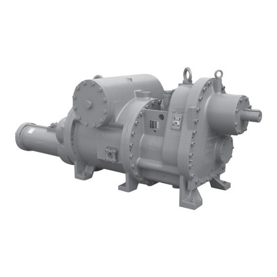
ROTARY SCREW COMPRESSOR
MODELS 100, 150, 200, 250, 300, 400 and 450
THIS MANUAL CONTAINS RIGGING, ASSEMBLY, START-UP,
AND MAINTENANCE INSTRUCTIONS. READ THOROUGHLY
BEFORE BEGINNING INSTALLATION. FAILURE TO FOLLOW THESE
INSTRUCTIONS MAY RESULT IN PERSONAL INJURY OR DEATH,
DAMAGE TO THE UNIT, OR IMPROPER OPERATION.
Please check www.johnsoncontrols.com/frick for the latest version of this publication.
NGC
Gas Compressor
ALL GEAR RATIOS
Form 070.550-IOM (JUN 2016)
INSTALLATION - OPERATION - MAINTENANCE
File:
EQUIPMENT MANUAL - Section 070
Replaces:
070.550 - IOM (MAR 2015)
Dist:
3, 3a, 3b, 3c
Advertisement
Table of Contents
Troubleshooting

Subscribe to Our Youtube Channel
Related Manuals for Johnson Controls Frick NGC 100


Summary of Contents for Johnson Controls Frick NGC 100
- Page 1 Form 070.550-IOM (JUN 2016) INSTALLATION - OPERATION - MAINTENANCE File: EQUIPMENT MANUAL - Section 070 Replaces: 070.550 - IOM (MAR 2015) Dist: 3, 3a, 3b, 3c ROTARY SCREW COMPRESSOR Gas Compressor MODELS 100, 150, 200, 250, 300, 400 and 450 ALL GEAR RATIOS THIS MANUAL CONTAINS RIGGING, ASSEMBLY, START-UP, AND MAINTENANCE INSTRUCTIONS.
-
Page 2: Table Of Contents
070.550-IOM (JUN 2016) NGC GAS ROTARY SCREW COMPRESSOR Page 2 INSTALLATION - OPERATION - MAINTENANCE Contents OPERATION GENERAL INFORMATION OPERATION AND START-UP INSTRUCTIONS ....15 PREFACE ................3 COMPRESSOR HYDRAULIC SYSTEM .......15 COMPRESSOR BASICS ..........3 FIGURE 12 - HYDRAULIC SCHEMATIC ......15 DESCRIPTION .............. -
Page 3: General Information
14. Integral gearbox available with 4 different gear ratios for NGC COMPRESSOR all models except the NGC 400/450 which have 6 ratios The Johnson Controls - Frick NGC rotary screw compressor available. utilizes mating asymmetrical profile helical rotors to provide 15. -
Page 4: Oil Pump
MODEL, SERIAL, and NGC 150A. If you change the gear, please make records of Johnson Controls - Frick SALES ORDER NUMBERS the change and mark the compressor with the actual gear from these data plates. See Figure 1. -
Page 5: Long Term Storage
SM1. The standard Johnson Controls-Frick Warranty for an NGC 2. Break vacuum with dry nitrogen and bring pressure to screw compressor covers twelve (12) months from start-up zero psig. -
Page 6: Construction Details
23 % 9.89 4.75 VOLUMIZER VARIABLE VOLUME RATIO CONTROL: The 20 % 16.94 6.95 Johnson Controls - Frick compressor includes a patented 12 % 8.99 3.69 method of varying the internal volume ratio to match the 26 % 15.48 6.40 system pressure ratio. -
Page 7: Installation
Very small amounts of sour gasses and moisture are acceptable if in accordance with Johnson Controls-Frick limits are identical to standard non gear-driven compressors. Refer to Johnson Controls - Frick Compressor Control Panel specifications and approvals. Contact Johnson Controls- publication 090.040-SD for additional information on Frick Compressor Engineering for guidelines. - Page 8 070.550-IOM (JUN 2016) NGC GAS ROTARY SCREW COMPRESSOR Page 8 INSTALLATION Figure 3. Port Locations, NGC 100/150.
- Page 9 NGC GAS ROTARY SCREW COMPRESSOR 070.550-IOM (JUN 2016) INSTALLATION Page 9 NOTE: Model 250 is shown for illustrative purposes only. Configurations of other compressors will vary. Figure 4. Port Locations, NGC 200/250.
- Page 10 070.550-IOM (JUN 2016) NGC GAS ROTARY SCREW COMPRESSOR Page 10 INSTALLATION Figure 5. Port Locations, NGC 300.
- Page 11 NGC GAS ROTARY SCREW COMPRESSOR 070.550-IOM (JUN 2016) INSTALLATION Page 11 NOTE: Model 400 is shown for illustrative purposes only. Configurations of other compressors will vary. Figure 6. Port Locations, NGC 400/450.
-
Page 12: Holding Charge And Storage
NGO and E160-802 SPC for guidance. installation. OIL FILTER(S) CAUTION Use of filter elements other than Johnson Controls - Frick Allow proper spacing for servicing (see Dimensional must be approved in writing by Johnson Controls - Frick Outline Drawing). engineering or a warranty claim may be denied. Typical oil filter specification β... -
Page 13: Oil Pump
NGC GAS ROTARY SCREW COMPRESSOR 070.550-IOM (JUN 2016) INSTALLATION Page 13 OIL PUMP Set up the minimum distance between compressor shaft and engine shaft to allow for seal removal and gear cover NGC models that are supplied with an oil pump use an removal (see Outline drawings). -
Page 14: Electrical Installation
Check and redo the alignment after 200 hours of in the OPERATION chapter. For control system information operation. See the maintenance schedule. refer to Johnson Controls - Frick Compressor Control Panel S90-010. See wiring diagram in Figure 7. ELECTRICAL INSTALLATION... -
Page 15: Operation And Start-Up Instructions
OPERATION AND START-UP INSTRUCTIONS COMPRESSOR HYDRAULIC SYSTEM (24 VDC Solenoid valves and distribution block are The Johnson Controls - Frick NGC Rotary Screw Compressor available as sales order option) will be a component in an integrated system. As such the... -
Page 16: Volumizer Volume Ratio Control
070.550-IOM (JUN 2016) NGC GAS ROTARY SCREW COMPRESSOR Page 16 OPERATION High stage compressor loading: The compressor loads VOLUMIZER VOLUME RATIO CONTROL when MSV solenoid YY2 is energized and oil flows from the Open valve at SC3 unload side of the cylinder out port SC1, through valve Open valve at SC4 ports A and T to compressor suction. -
Page 17: Maintenance
JOHNSON CONTROLS - FRICK. A number compressor type available today about ingestion of some of special tools are needed to do a gear change and a liquid, they are not liquid pumps. -
Page 18: Recommended Maintenance Schedule
070.550-IOM (JUN 2016) NGC GAS ROTARY SCREW COMPRESSOR Page 18 MAINTENANCE RECOMMENDED MAINTENANCE PROGRAM on a regular basis. It is a valuable tool that can identify the In order to obtain maximum compressor performance and presence of moisture, acid, metallics and other contaminants ensure reliable operation, a regular maintenance program that will shorten compressor life if not corrected. -
Page 19: Torsional Analysis
NGC GAS ROTARY SCREW COMPRESSOR 070.550-IOM (JUN 2016) INSTALLATION - OPERATION - MAINTENANCE Page 19 TORSIONAL ANALYSIS Jackshaft Male Rotor Figure 14. Torsional Analysis, NGC and NGCH 400/450 Driveline and Gear Dimensions. NGC/NGCH Driveline Dimensions (Less Gears) NGC/NGCH Gear Dimensions SEGMENT DIAMETER* LENGTH*... -
Page 20: Vibration Analysis
2. Only use Frick filter elements. Substitutions must be problem. Once the cause has been identified and confirmed approved in writing by Johnson Controls - Frick engineering make the necessary corrections. or warranty claim may be denied. -
Page 21: Troubleshooting The Ngc Compressor
• Piston Seals worn out/damaged. Contact Johnson Controls - Frick Service for assistance. NOTICE Unless the Service Technician has been certified by Johnson Controls – Frick to rebuild our compressors, troubleshooting the compressor is limited to identifying the probable cause. If a mechanical problem is suspected contact Johnson Controls –... -
Page 22: Capacity Linear Transmitter Replacement - Slide Valve
070.550-IOM (JUN 2016) NGC GAS ROTARY SCREW COMPRESSOR Page 22 MAINTENANCE TROUBLESHOOTING GUIDE (cont.) NOTICE CAPACITY LINEAR TRANSMITTER REPLACEMENT - SLIDE For calibration of the Volumizer unit, refer to the Analog ® VALVE Calibration instructions in publication 090-020 O. The Capacity Linear Transmitter is located on the end of the compressor cylinder (see Figure 15). - Page 23 NGC GAS ROTARY SCREW COMPRESSOR 070.550-IOM (JUN 2016) MAINTENANCE Page 23...
-
Page 24: Drive Train Alignment
070.550-IOM (JUN 2016) NGC GAS ROTARY SCREW COMPRESSOR Page 24 MAINTENANCE DRIVE TRAIN ALIGNMENT Ambient Temperature at Time of Alignment ___________________ Oil Separator Temp. at Time of Alignment _________ Engine Coupling Type _________________ Size _______________ Distance Between Coupling Hub Faces ____________ Amount of Shims used to Correct ________________ Soft Foot Check OK as Found... -
Page 25: Vibration Data Sheet
NGC GAS ROTARY SCREW COMPRESSOR 070.550-IOM (JUN 2016) INSTALLATION - OPERATION - MAINTENANCE Page 25 VIBRATION DATA SHEET Date: ________________________________________________ Sales Order Number: _________________________________ End User: _____________________________________________ Installing Contractor: _________________________________ Address: ______________________________________________ Service Technician: ___________________________________ ______________________________________________________ ______________________________________________________ Equipment ID (As in Microlog): ___________________________ Compressor Serial Number: _____________________________ Unit Serial Number: ____________________________________ National Board Number: ________________________________... -
Page 26: Index
070.550-IOM (JUN 2016) NGC GAS ROTARY SCREW COMPRESSOR Page 26 INSTALLATION - OPERATION - MAINTENANCE Index accumulator, 3 hermetic enclosure, 19 radial loads, 5 acid formation, 3 High capacity roller bearings, 5 RIGGING AND HANDLING, 12 Allowable Flange Loads, 12 HOLDING CHARGE, 12 rotor housing, 6 angular-contact bearings, 5... - Page 27 NGC GAS ROTARY SCREW COMPRESSOR 070.550-IOM (JUN 2016) INSTALLATION - OPERATION - MAINTENANCE Page 27 under-compression, 6 unloading, 6 vacuum, 4 Vacuum, 14 vacuum pump, 14 valve ports, 16 VAPOR PUMP, 3 Vi, 16 vibration analysis, 13, 16, 18 Vibration Data Sheet, 23 vibration level, 17 VOLUME RATIO, 16 VOLUMIZER®...
- Page 28 JOHNSON CONTROLS Supersedes: 070.800 - IOM (2015-03) 100 CV Avenue Subject to change without notice Waynesboro, PA 17268-1206 USA Published in USA • 06/16 • PDF Phone: 717-762-2121 • FAX: 717-762-8624 www.johnsoncontrols.com/frick © 2016 Johnson Controls Inc. - ALL RIGHTS RESERVED...
Need help?
Do you have a question about the Frick NGC 100 and is the answer not in the manual?
Questions and answers