Table of Contents
Advertisement
Quick Links
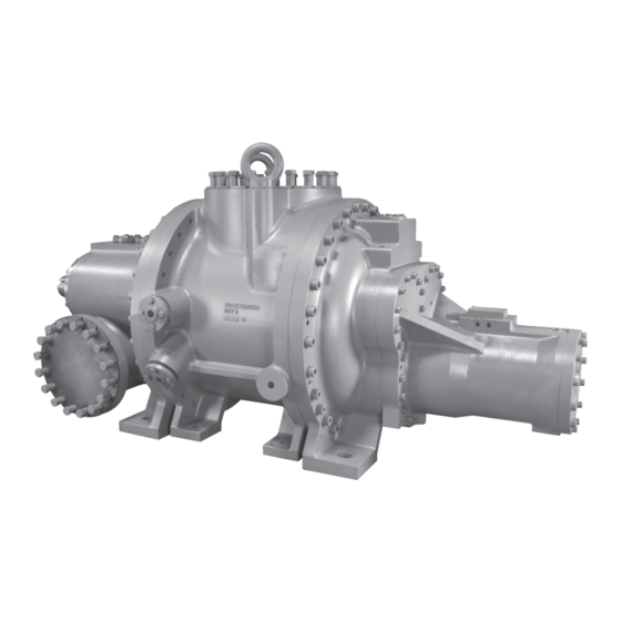
ROTARY SCREW COMPRESSOR
MODELS 408S, 408L, 408XL
THIS MANUAL CONTAINS RIGGING, ASSEMBLY, START-UP,
AND MAINTENANCE INSTRUCTIONS. READ THOROUGHLY
BEFORE BEGINNING INSTALLATION. FAILURE TO FOLLOW THESE
INSTRUCTIONS MAY RESULT IN PERSONAL INJURY OR DEATH,
DAMAGE TO THE UNIT, OR IMPROPER OPERATION.
Please check www.jci.com/frick for the latest version of this publication.
Form 070.250-IOM (APR 2011)
INSTALLATION - OPERATION - MAINTENANCE
File:
Replaces:
Dist:
408 mm
SERVICE MANUAL - Section 070
NOTHING
3, 3a, 3b, 3c
Advertisement
Table of Contents
Troubleshooting

Related Manuals for Johnson Controls Frick 408S


Summary of Contents for Johnson Controls Frick 408S
- Page 1 Form 070.250-IOM (APR 2011) INSTALLATION - OPERATION - MAINTENANCE File: SERVICE MANUAL - Section 070 Replaces: NOTHING Dist: 3, 3a, 3b, 3c 408 mm ROTARY SCREW COMPRESSOR MODELS 408S, 408L, 408XL THIS MANUAL CONTAINS RIGGING, ASSEMBLY, START-UP, AND MAINTENANCE INSTRUCTIONS. READ THOROUGHLY BEFORE BEGINNING INSTALLATION.
-
Page 2: Table Of Contents
070.250-IOM (APR 11) 408 MM ROTARY SCREW COMPRESSOR Page 2 INSTALLATION - OPERATION - MAINTENANCE Contents GENERAL INFORMATION OPERATION PREFACE ................3 OPERATION AND START-UP INSTRUCTIONS ....16 DESIGN LIMITATIONS ............3 COMPRESSOR HYDRAULIC SYSTEM .......16 JOB INSPECTION .............. 3 VOLUMIZER VOLUME RATIO CONTROL ......16 STANDARD BARE COMPRESSOR ........ -
Page 3: General Information
Frick 408 mm compressors are designed for operation Figure 1 - Identification Data Plate within the pressure and temperature limits which are specified by Johnson Controls-Frick and our COOLWARE ™ Rotary screw compressor serial numbers are defined by the selection software. They are primarily used for compressing following information: refrigerant gas and most hydrocarbon gasses. -
Page 4: Long Term Storage
SM1. Evacuation lines are to be changes in temperature, dusty atmosphere, etc. connected to the Schrader valves provided with the The standard Johnson Controls-Frick Warranty for a compressor. One valve is connected to compressor suction. 408 mm screw compressor covers twelve (12) months from The other valves are located on the cylinder. -
Page 5: Maintaining Compressor
Actual system operating conditions operation. may necessitate the need for piping systems other than those addressed by CES 6606. Contact Johnson Controls- 6. A hydraulic cylinder to operate the slide stop and slide Frick Service for assistance. -
Page 6: Demand Oil Pump
The slide valve those addressed by CES 6606. Contact Johnson Controls- moves axially under the rotors to provide fully modulated FRICk Service for assistance. -
Page 7: Installation
Please see CoolWare to determine the limits for a specific application. The rotor and bearing design set limitations of the 408 mm compressors must not be exceeded (See CoolWare). Refer to Johnson Controls-Frick Compressor Control Panel instruction 090.040-O for additional information on setpoint limits. OUTLINE DIMENSIONS Drawings for reference only can be found on the following pages. - Page 8 070.250-IOM (APR 11) 408 MM ROTARY SCREW COMPRESSOR Page 8 INSTALLATION COMPRESSOR PORT LOCATIONS - 408 MM ST-1 SC-5 SC-7 SM-1 SC-1 SC-3 SC-9 SC-9 SV-1 ST-2 SC-6 SC-10 VIEW C-C SC-11...
- Page 9 408 MM ROTARY SCREW COMPRESSOR 070.250-IOM (APR 11) INSTALLATION Page 9 COMPRESSOR PORT LOCATIONS - 408 MM SUCTION SUCTION COMPRESSORS 4018 & 4021 COMPRESSOR 4013 16"-300# ANSI FLANGE 12"-300# ANSI FLANGE 1¼-7 UNC-2B x 2.56DP 1 -7 UNC-2B x 2.18 DP ¹⁄₈...
- Page 10 070.250-IOM (APR 11) 408 MM ROTARY SCREW COMPRESSOR Page 10 INSTALLATION COMPRESSOR PORT LOCATIONS - 408 MM SC-13 SC-14 VIEW D-D SL-1 SC-3 SC-2 SC-4 SC-2 SL-2 DISCHARGE 12 -300# ANSI FLANGE " 1 -7 UNC-2B x 3.00 DP ¹⁄₈ 16X ON 17.750 B.C.
- Page 11 408 MM ROTARY SCREW COMPRESSOR 070.250-IOM (APR 11) INSTALLATION Page 11 COMPRESSOR PORT LOCATIONS - 408 MM PORT SIZE O-RING DESCRIPTION SB-2 1"-300# ANSI, 5/8-11 UNC, 1.37 DP. — INLET BEARING & BALANCE PISTON SB-3 1½-300# ANSI, 3/4-10 UNC, 1.75 DP. —...
-
Page 12: Holding Charge And Storage
CAUTION Every 408 mm compressor is pressure and leak tested at the Allow proper spacing for servicing (see Dimensional Johnson Controls–Frick factory and then thoroughly evacu- Outline Drawing). ated and charged with dry nitrogen to ensure its integrity during shipping and short term storage prior to installation. -
Page 13: Compressor Oil
. If you are using the Johnson Controls–Frick motor mount, The oil supply system for the compressor must be designed the mount is machined to ensure that motor to compressor for a total pressure drop of no more than 15 psi with a new alignment is in specification (see the above “MOTOR... -
Page 14: Dehydration / Evacuation Test
Oil temperatures as high as 170°F can be used to achieve the necessary discharge temperature to prevent moisture from condensing in the oil separator. Contact Johnson Controls–Frick for additional information for natural gas compression. The main oil injection line that is connected to port SM1... -
Page 15: Directional Control Valves
408 MM ROTARY SCREW COMPRESSOR 070.250-IOM (APR 11) INSTALLATION Page 15 Figure 8 - Wiring Diagram for Slide Valve Transmitter DIRECTIONAL CONTROL VALVES Solenoids YY1, YY2, YY3 and YY4 must be wired to give the correct function. A description of their function is given in the OPERATION chapter. -
Page 16: Operation
070.250-IOM (APR 11) 408 MM ROTARY SCREW COMPRESSOR Page 16 OPERATION Booster Compressor Loading: The compressor loads when OPERATION SV solenoid YY2 is energized and oil flows from the oil manifold through valve ports P and B to cylinder port SC2 OPERATION AND START-UP INSTRUCTIONS and enters the load side of the cylinder. -
Page 17: Initial Start-Up
408 MM ROTARY SCREW COMPRESSOR 070.250-IOM (APR 11) OPERATION Page 17 DIRECTION CONTROL CUSTOMER SV-2 VALVE SV-3 SUPPLIED PUMP SCREW IN FLOW DIRECTION REGULATING CONTROL NEEDLE VALVE VALVE COMPRESSOR TOP VIEW HYDRAULIC SCHEMATIC 408 MM (INCREASE VI) YY3 YY4 (DECREASE VI) (UNLOAD) YY1 YY2 (LOAD) Figure 11 - Hydraulic Schematic... -
Page 18: Maintenance
070.250-IOM (APR 11) 408 MM ROTARY SCREW COMPRESSOR Page 18 MAINTENANCE MAINTENANCE 5. Protect the compressor during long periods of shutdown. If the compressor will be sitting for long periods without running, it is advisable to evacuate to low pressure GENERAL INFORMATION and charge with dry nitrogen or oil. -
Page 19: Oil Quality And Analysis
2. Use vibration readings taken from the new unit at start- 2. Only use Frick filter elements. Substitutions must be up as the baseline reference. approved in writing by Johnson Controls-Frick engineering or warranty claim may be denied. 3. Evaluate vibration readings carefully as the instrument range and function used can vary. -
Page 20: Capacity Linear Transmitter Replacement
070.250-IOM (APR 11) 408 MM ROTARY SCREW COMPRESSOR Page 20 MAINTENANCE The third step is to identify the most likely cause and take The linear transmitter, with hermetic, enclosure is based on action to correct the problem. If the symptoms are not the inductive measuring principle. -
Page 21: Troubleshooting The 408 Mm Compressor
NOTICE Unless the Service Technician has been certified by Johnson Controls–Frick to rebuild our compressors, troubleshooting the compressor is limited to identifying the probable cause. If a mechanical problem is suspected, contact Johnson Controls–Frick Service. DO NOT ATTEMPT TO DISASSEMBLE COMPRESSOR. -
Page 22: Troubleshooting The Oil Pump And System
070.250-IOM (APR 11) 408 MM ROTARY SCREW COMPRESSOR Page 22 MAINTENANCE TROUBLESHOOTING THE OIL PUMP AND SYSTEM SYMPTOM PROBABLE CAUSES and CORRECTIONS PUMP WILL NOT PRODUCE Check that service valves are open. ENOUGH OIL PRESSURE AT Filter cartridges may be blocked. Check PSID across filters. START-UP Strainer may be blocked. - Page 23 408 MM ROTARY SCREW COMPRESSOR 070.250-IOM (APR 11) MAINTENANCE Page 23 DRIVE TRAIN ALIGNMENT Ambient Temperature at Time of Alignment _______ Oil Separator Temperature at Time of Alignment_________ Motor Coupling Type ___________ Size ___________ Distance Between Coupling Hub Faces __________ Soft Foot Check OK as Found Shimming Required...
-
Page 24: Vibration Data Sheet
070.250-IOM (APR 11) 408 MM ROTARY SCREW COMPRESSOR Page 24 MAINTENANCE VIBRATION DATA SHEET Date: __________________________________________ Sales Order Number: ________________________________ End User: _______________________________________ Installing Contractor: ________________________________ Address: __________________________________________ Service Technician: __________________________________ Final Hot Alignment Equipment ID (As in Microlog): ____________________ Compressor Serial Number: __________________________ Unit Serial Number: _________________________________ Face... - Page 25 408 MM ROTARY SCREW COMPRESSOR 070.250-IOM (APR 11) INSTALLATION - OPERATION - MAINTENANCE Page 25 Index accumulator, 3 identification data plate, 3 Allowable Flange Loads, 12 Installation, 7 angular-contact bearings, 5 insulated, 16 Antifriction bearings, 6 ASHRAE, 3 lifting rings, 12 linear transmitter, 20 balance piston, 5 load surges, 3...
- Page 26 070.250-IOM (APR 11) 408 MM ROTARY SCREW COMPRESSOR Page 26 INSTALLATION - OPERATION - MAINTENANCE seal life, 5 vacuum, 4 seal well, 5 Vacuum, 14 serial number, 3 vacuum pump, 14 shaft alignment, 20 valve ports, 16 Shaft rotation, 5 Vapor Pump, 3 shipping gauges, 12 Vi, 16...
- Page 27 408 MM ROTARY SCREW COMPRESSOR 070.250-IOM (APR 11) INSTALLATION - OPERATION - MAINTENANCE Page 27...
- Page 28 Form 070-250 IOM (2011-04) JOHNSON CONTROLS Supersedes: NOTHING 100 CV Avenue Subject to change without notice Waynesboro, PA 17268-1206 USA Published in USA • 0714 PDF Phone: 717-762-2121 • FAX: 717-762-8624 www.jci.com/frick © 2014 Johnson Controls Inc. - ALL RIGHTS RESERVED...
Need help?
Do you have a question about the Frick 408S and is the answer not in the manual?
Questions and answers