Table of Contents
Advertisement
Quick Links
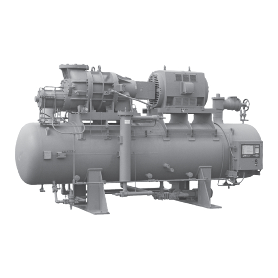
RWB II
ROTARY SCREW COMPRESSOR UNITS
496 through 1080
THIS MANUAL CONTAINS RIGGING, ASSEMBLY, START-UP,
AND MAINTENANCE INSTRUCTIONS. READ THOROUGHLY
BEFORE BEGINNING INSTALLATION. FAILURE TO FOLLOW THESE
INSTRUCTIONS COULD RESULT IN DAMAGE OR IMPROPER
OPERATION OF THE UNIT.
Please check www.johnsoncontrols.com for the latest version of this publication.
Form 070-210 IOM (JAN 2009)
INSTALLATION - OPERATION - MAINTENANCE
File:
Replaces:
Dist:
ALL REFRIGERANTS
MODELS
EQUIPMENT MANUAL - Section 70
S70-200 IOM (SEP 05)
3, 3a, 3b, 3c
Advertisement
Table of Contents
Troubleshooting

Related Manuals for Johnson Controls Frick RWB II PLUS 496


Summary of Contents for Johnson Controls Frick RWB II PLUS 496
- Page 1 Form 070-210 IOM (JAN 2009) INSTALLATION - OPERATION - MAINTENANCE File: EQUIPMENT MANUAL - Section 70 Replaces: S70-200 IOM (SEP 05) Dist: 3, 3a, 3b, 3c RWB II ROTARY SCREW COMPRESSOR UNITS ALL REFRIGERANTS MODELS 496 through 1080 THIS MANUAL CONTAINS RIGGING, ASSEMBLY, START-UP, AND MAINTENANCE INSTRUCTIONS.
-
Page 2: Table Of Contents
070-210 IOM (JAN 09) RWB II ROTARY SCREW COMPRESSOR UNITS Page 2 INSTALLATION - OPERATION - MAINTENANCE Contents PREFACE ................3 LOW AMBIENT OPERATION .......... 21 DESIGN LIMITATIONS ............3 POWER ASSIST KIT ............21 JOB INSPECTION ............. 3 INITIAL START-UP ............22 TRANSIT DAMAGE CLAIMS .......... -
Page 3: Preface
RWB II ROTARY SCREW COMPRESSOR UNITS 070-210 IOM (JAN 09) GENERAL INFORMATION Page 3 preFACe COMpreSSOr and UNIT IDeNTIFICATION This manual has been prepared to acquaint the owner and Each compressor unit has 2 identifica tion data plates. The compressor data plate containing compressor model and serviceman with the INSTALLATION, OPERATION, and MAIN TEN ANCE procedures as factory recommended for serial number is mounted on the compressor body. -
Page 4: Installation
070-210 IOM (JAN 09) RWB II ROTARY SCREW COMPRESSOR UNITS Page 4 INSTALLATION INSTALLATION ALLOWABLe FLANGe LOADS NOZ. MOMeNTS (ft-lbf) LOAD (lbf) FOUNDATION SIZe AXIAL VerT. LAT. AXIAL VerT. LAT. Each rWB II Rotary Screw Compressor Unit is shipped mounted on a wooden skid which must be removed prior to unit installation. -
Page 5: Motor Mounting
RWB II ROTARY SCREW COMPRESSOR UNITS 070-210 IOM (JAN 09) INSTALLATION Page 5 MOTOr MOUNTING DBZ-B COUpLING – The Thomas DBZ-B coupling is used on applications above 600 HP and with sleeve bearing mo- The following procedure is required only when the motor is tors that do not have axial end float constraint. - Page 6 070-210 IOM (JAN 09) RWB II ROTARY SCREW COMPRESSOR UNITS Page 6 INSTALLATION SerIeS 52 COUpLING – The Thomas Series 52 coupling is If the motor is coupled to the compressor using a fixed-end- play coupling and the motor is not properly centered, the also used on applications above 600 HP.
-
Page 7: Coupling Alignment Procedure
RWB II ROTARY SCREW COMPRESSOR UNITS 070-210 IOM (JAN 09) INSTALLATION Page 7 COUpLING ALIGNMeNT prOCeDUre The life of the compressor shaft seal and bearings, as well as the life of the motor bearings, is dependent upon proper coupling alignment. Couplings may be aligned at the factory but realignment MUST ALWAYS be done on the job site after the unit is securely mounted on its founda tion. - Page 8 070-210 IOM (JAN 09) RWB II ROTARY SCREW COMPRESSOR UNITS Page 8 INSTALLATION pArALLeL ALIGNMeNT 6. To check parallel alignment, as shown in Figure 4, reposi- tion dial indicator so the stem is in contact with the rim of the compressor hub, as shown in Figure 5.
-
Page 9: Hot Alignment Of Compressor/Motor
RWB II ROTARY SCREW COMPRESSOR UNITS 070-210 IOM (JAN 09) INSTALLATION Page 9 HOT ALIGNMeNT OF COMpreSSOr/MOTOr COMpreSSOr OIL Hot alignments can only be made DO NOT MIX OILS of different after the unit has operated for sev- brands, manufacturers, or types. eral hours and all components are Mixing of oils may cause exces- at operating temperatures. -
Page 10: Oil Heater(S)
070-210 IOM (JAN 09) RWB II ROTARY SCREW COMPRESSOR UNITS Page 10 INSTALLATION OIL HeATer(S) The Level Control method utilizes a float level control on the receiver to close a solenoid valve feeding the evapora- Standard units are equipped with 2 or 3 500 or 1000 watt oil tor when the liquid falls below that amount necessary for 5 heaters, providing sufficient heat to maintain the oil tempera- minutes of liquid injection oil cooling. -
Page 11: Water-Cooled Oil Cooling (Option Al)
RWB II ROTARY SCREW COMPRESSOR UNITS 070-210 IOM (JAN 09) INSTALLATION Page 11 WATer-COOLeD OIL COOLING (OpTION AL) 2. A shell and tube oil cooler with: Shell Side: Oil 400 lb design The plate and shell type water-cooled oil cooler is mounted Tube Side: Refrigerant 400 lb design on the unit complete with all oil piping. - Page 12 070-210 IOM (JAN 09) RWB II ROTARY SCREW COMPRESSOR UNITS Page 12 INSTALLATION OIL TeMperATUre CONTrOL - Oil temperature will gen- shell side (oil side) safety valve directly into the oil separator, as shown in the P & I diagrams section. erally run about 15 - 35°F above condensing tempera ture.
-
Page 13: Economizer - High Stage (Optional)
RWB II ROTARY SCREW COMPRESSOR UNITS 070-210 IOM (JAN 09) INSTALLATION Page 13 eCONOMIZer - HIGH STAGe (OpTIONAL) The recommended economizer systems are shown below. Notice that in all systems there should be a strainer (STR) The economizer option provides an increase in system ca- and a check valve (VCK) between the economizer vessel pacity and efficiency by subcooling liquid from the condenser and the economizer port on the compressor. -
Page 14: Electrical
070-210 IOM (JAN 09) RWB II ROTARY SCREW COMPRESSOR UNITS Page 14 INSTALLATION the PRR unit and the liquid feed solenoid on the DX vessel Prolonged low voltage may cause the motor to stall and overheat before the motor contactor is manually turned off of a common signal to avoid liquid overfeed on the DX economizer system. -
Page 15: Current Transformer (Ct) Ratios
RWB II ROTARY SCREW COMPRESSOR UNITS 070-210 IOM (JAN 09) INSTALLATION Page 15 5. For customer-supplied across-the-line starters, a shunt- CUrreNT TrANSFOrMer (CT) rATIOS ing devicemust be installed across the Current Transformer The CT ratio for various motor sizes (with a 5 amp second- (terminals 3 &... -
Page 16: Mini Mum Burden Ratings
070-210 IOM (JAN 09) RWB II ROTARY SCREW COMPRESSOR UNITS Page 16 OPERATION OperATION 7. One each normally open compressor motor and oil pump motor starter auxiliary contact should be supplied and in and STArT-Up INSTrUCTIONS addition to the compressor and oil pump motor starter coils, the CT and CPT secondaries wired as shown on the starter The Frick RWB II Rotary Screw Compressor Unit is an inte- package wiring diagram. -
Page 17: Cycling Full-Lube Oil System
RWB II ROTARY SCREW COMPRESSOR UNITS 070-210 IOM (JAN 09) OPERATION Page 17 CO M pre S S O r rOTAT ION I S ferential has been reached between suction and discharge, CLOCKWISe WHeN FACING THe the PRELUBE pump will shut down and the lubrication oil will COMpreSSOr DrIVe SHAFT. -
Page 18: Compressor Hydraulic System
070-210 IOM (JAN 09) RWB II ROTARY SCREW COMPRESSOR UNITS Page 18 OPERATION COMpreSSOr HYDrAULIC SYSTeM normal operation. If an oil level develops and remains in the sight glass, a problem in the oil return separation system or The compressor hydraulic system moves the movable slide compressor operation has developed. -
Page 19: Compressor Oil Cooling Systems
RWB II ROTARY SCREW COMPRESSOR UNITS 070-210 IOM (JAN 09) OPERATION Page 19 Figure 23 VOLUMIZer® VOLUMe rATIO CONTrOL is then supplied to the tempera ture control valve (TCV). The temperature control valve is equal ized to a constant back Vi Increase pressure by the dif feren tial pressure control valve (PDCV). -
Page 20: Liquid Injection Adjustment Procedure
070-210 IOM (JAN 09) RWB II ROTARY SCREW COMPRESSOR UNITS Page 20 OPERATION Solenoid valve SV5 is energized by the micro processor when to raise the oil temperature, and counter-clockwise to lower the oil temperature. After the adjustment has been made the temperature sensor, in stalled in the oil manifold, exceeds the LICO set point. -
Page 21: Suction Check Valve
RWB II ROTARY SCREW COMPRESSOR UNITS 070-210 IOM (JAN 09) OPERATION Page 21 SUCTION CHeCK VALVe HV-2 also should be closed on systems that utilize autocycle to restart the compressor, based on increase in system Low temperature booster compressor operations require suction pressure during shutdown, if slowly bleeding the a more positive suction check valve closure. -
Page 22: Initial Start-Up
070-210 IOM (JAN 09) RWB II ROTARY SCREW COMPRESSOR UNITS Page 22 OPERATION INITIAL STArT-Up 2. For proper and safe operation the compressor must be run at the proper speed and discharge pressure. Exceeding Initial start-up must be performed under the super vision of a design conditions creates a potential hazard. -
Page 23: Maintenance
RWB II ROTARY SCREW COMPRESSOR UNITS 070-210 IOM (JAN 09) MAINTENANCE Page 23 MAINTeNANCe GeNerAL INFOrMATION This section provides instructions for normal main tenance, a recommended maintenance program, troubleshooting and 1. IF UNIT IS rUNNING, preSS STOp KeY. correction guides, and typical P and I diagrams. For typical 2. -
Page 24: General Instructions For Replacing Compressor Unit Components
070-210 IOM (JAN 09) RWB II ROTARY SCREW COMPRESSOR UNITS Page 24 MAINTENANCE GeNerAL INSTrUCTIONS FOr repLACING 2. Close outlet then inlet service valves of filter being serviced. COMpreSSOr UNIT COMpONeNTS. 3. Open bleed valve and purge pressure from the oil filter When replacing or repairing components which are exposed cartridge. -
Page 25: Strainer - Full Lube Oil Pump
RWB II ROTARY SCREW COMPRESSOR UNITS 070-210 IOM (JAN 09) MAINTENANCE Page 25 STrAINer - FULL LUBe OIL pUMp 13. Close disconnect switches for compressor and oil pump motor starters. To clean the full-lube oil pump strainer, the unit must be shut 14. -
Page 26: Recommended Maintenance Program
070-210 IOM (JAN 09) RWB II ROTARY SCREW COMPRESSOR UNITS Page 26 MAINTENANCE reCOMMeNDeD MAINTeNANCe prOGrAM ordinances, before opening to atmosphere. The separa- tor MUST be equalized to atmospheric pressure. In order to obtain maximum compressor unit perform ance Oil entrained refrigerant may vapor- and ensure reliable operation, a regular main tenance pro- ize, causing a separator pressure gram should be followed. -
Page 27: Operating Log
RWB II ROTARY SCREW COMPRESSOR UNITS 070-210 IOM (JAN 09) MAINTENANCE Page 27 GreASe COMpATIBILITY NOTe: The Frick oil charge shipped with the unit is the best suited lubricant for the conditions specified at the If it becomes necessary to mix greases, be careful not to time of purchase. -
Page 28: Troubleshooting Guide
070-210 IOM (JAN 09) RWB II ROTARY SCREW COMPRESSOR UNITS Page 28 MAINTENANCE TrOUBLeSHOOTING GUIDe The following list of abnormal system conditions can cause abnormal operation of the RWB II compressor unit: Successful problem solving requires an organized ap proach 1. -
Page 29: Pressure Transducers - Testing
RWB II ROTARY SCREW COMPRESSOR UNITS 070-210 IOM (JAN 09) MAINTENANCE Page 29 preSSUre TrANSDUCerS - TeSTING 11. Since the discharge pressure, PE-3, cannot be closed off from its sensing point (code require ments), close all transduc- Pressure transducers are located on a covered manifold ers from atmosphere and open them to their sensing points directly behind the microprocessor console See Figure 27. - Page 30 070-210 IOM (JAN 09) RWB II ROTARY SCREW COMPRESSOR UNITS Page 30 MAINTENANCE preSSUre TrANSDUCer CONVerSION DATA 100 psi 200 psi 300 psi 500 psi Sensor range - pSIG* range - pSIG* range - pSIG* range - pSIG* Voltage high high high high...
-
Page 31: Position Potentiometer Replacement And Adjust Ment
RWB II ROTARY SCREW COMPRESSOR UNITS 070-210 IOM (JAN 09) MAINTENANCE Page 31 SV pOSITION pOTeNTIOMeTer VOLUMIZer pOTeNTIOMeTer ® repLACeMeNT AND ADJUST MeNT repLACeMeNT The Slide Valve Position potentiometer is located on the end The VOLUMIZER potentiometer is located under a cover ®... -
Page 32: Troubleshooting The Rwb Ii Compressor
070-210 IOM (JAN 09) RWB II ROTARY SCREW COMPRESSOR UNITS Page 32 MAINTENANCE TrOUBLeSHOOTING THe rWB II COMpreSSOr SYMpTOM prOBABLe CAUSeS and COrreCTIONS EXCESSIVE NOISE and VIBRATION Main oil injection valve may be closed. Open valve. Bearing damage or excessive wear. CONTACT Frick Factor or Frick. Coupling loose on shaft. -
Page 33: Hydraulic System
RWB II ROTARY SCREW COMPRESSOR UNITS 070-210 IOM (JAN 09) MAINTENANCE Page 33 TrOUBLeSHOOTING THe HYDrAULIC SYSTeM SYMpTOM prOBABLe CAUSeS and COrreCTIONS SLIDE VALVE WILL NOT LOAD OR Solenoid coils may be burned out, replace. UNLOAD Valve may be closed. Open hydraulic service valves. Solenoid spool may be stuck or centering spring broken, replace. -
Page 34: Prelube Pump System
070-210 IOM (JAN 09) RWB II ROTARY SCREW COMPRESSOR UNITS Page 34 MAINTENANCE TrOUBLeSHOOTING THe preLUBe pUMp SYSTeM SYMpTOM prOBABLe CAUSeS and COrreCTIONS PRELUBE PUMP WILL NOT Filter cartridge in filter F-2 may be clogged, replace. GENERATE SUFFICIENT OIL PRESSURE TO ALLOW Clean strainer before prelube pump inlet. -
Page 35: Liquid Injection Oil Cooling System
RWB II ROTARY SCREW COMPRESSOR UNITS 070-210 IOM (JAN 09) MAINTENANCE Page 35 TrOUBLeSHOOTING THe LIQUID INJeCTION OIL COOLING SYSTeM SYMpTOM prOBABLe CAUSeS and COrreCTIONS HIGH OIL TEMPERATURE Insufficient liquid supply, check receiver level and pressure drop at injection solenoid. Suction superheat too high, correct system problem. -
Page 36: Thermal Expansion Valves
070-210 IOM (JAN 09) RWB II ROTARY SCREW COMPRESSOR UNITS Page 36 MAINTENANCE THerMAL eXpANSION VALVeS In situations where system load conditions increase or de- crease over extended periods of time and the liquid injection thermal expansion valve is not adequate for the new condi- tions, an improvement in valve perfor mance may be achieved by increasing or decreasing discharge tube size. -
Page 37: Jordan Temperature Regulator Valve
RWB II ROTARY SCREW COMPRESSOR UNITS 070-210 IOM (JAN 09) MAINTENANCE Page 37 JOrDAN If the hole in the valve plate is to the left and the slot in the valve disc is on the top this valve is set for Direct Acting (see TeMperATUre reGULATOr VALVe figure 36). -
Page 38: Bare Compressor Mounting
070-210 IOM (JAN 09) RWB II ROTARY SCREW COMPRESSOR UNITS Page 38 MAINTENANCE Install the valve and adjust the spring tension accordingly SOLeNOID VALVe: Energizing, or opening, the solenoid valve pressurizes the balance piston with full oil pressure from to maintain the predetermined oil temperature. The recom- mended oil temperature is 130°F for ammonia. - Page 39 RWB II ROTARY SCREW COMPRESSOR UNITS 070-210 IOM (JAN 09) MAINTENANCE Page 39 p & I DIAGrAM - HOrIZONTAL SepArATOr BPCO HIGH STAGE OR SWING DUTY ONLY CONNECT TO SC-6 BOOSTER SUCTION GAS NOTE: VALVE BODY ASSEMBLY CONSISTS OF TO THE COMPR ONLY SUCTION STRAINER &...
- Page 40 070-210 IOM (JAN 09) RWB II ROTARY SCREW COMPRESSOR UNITS Page 40 MAINTENANCE p & I DIAGrAM - VerTICAL SepArATOr (w/prelube oil pump) NOTe: See Legend for symbol explanations.
- Page 41 RWB II ROTARY SCREW COMPRESSOR UNITS 070-210 IOM (JAN 09) MAINTENANCE Page 41 p & I DIAGrAM - OIL pUMpS V-310 V-310 SEPARATOR SEPARATOR FROM OIL FROM OIL COOLER COOLER SAFETY VALVE SAFETY VALVE LSLL LSLL 1 PUMPOUT 1 PUMPOUT CV-4 CV-4 HTR-1 / 500W...
- Page 42 070-210 IOM (JAN 09) RWB II ROTARY SCREW COMPRESSOR UNITS Page 42 MAINTENANCE p & I DIAGrAM - LIQUID INJeCTION OIL COOLING HV-2 HV-1 "B" LIQUID REFRIGERANT FROM THE RECEIVER SL-1 "C" HIGH PRESSURE LOCATE DRAIN AT LOW POINT OF PIPING RWB6LI1 LIQUID INJeCTION, SINGLe pOrT HV-2...
-
Page 43: Proper Installation Of Electronic Equipment In An Industrial Environment
RWB II ROTARY SCREW COMPRESSOR UNITS 070-210 IOM (JAN 09) PROPER INSTALLATION OF ELECTRONIC EQUIPMENT Page 43 prOper INSTALLATION OF eLeCTrONIC eQUIpMeNT IN AN INDUSTrIAL eNVIrONMeNT In today’s refrigeration plants, electronic controls have found loaded to its maximum capacity, the voltage dips are much their way into almost every aspect of refrigeration control. - Page 44 070-210 IOM (JAN 09) RWB II ROTARY SCREW COMPRESSOR UNITS Page 44 PROPER INSTALLATION OF ELECTRONIC EQUIPMENT GrOUNDING NEC size ratings are for safety purposes and not necessarily for adequate relaying of noise (EMI) to earth ground to avoid Grounding is the most important factor for successful opera- possible interference with sensitive equipment.
- Page 45 If the two circuits are run in the same conduit, transients on the 480 volt circuit will be Johnson Controls-Frick conduit requirements: induced onto the 120 volt circuit causing functional problems • For variable frequency drives (VFDs) of any type, threaded with the electronic control panel.
- Page 46 070-210 IOM (JAN 09) RWB II ROTARY SCREW COMPRESSOR UNITS Page 46 PROPER INSTALLATION OF ELECTRONIC EQUIPMENT Do not drill into an electronic control panel to locate conduit If the electronic control panel has a starter built into the same panel, be sure to run the higher voltage wires where connections.
- Page 47 LX pANeLS ™ The use of communications such as serial and ethernet Johnson Controls, Inc. does not advise nor support the in industrial environments are commonplace. The proper use of uninterrupted power supply systems for use with the installation of these networks is as important to the proper Quantum LX panel.
-
Page 48: Forms
070-210 IOM (JAN 09) RWB II ROTARY SCREW COMPRESSOR UNITS Page 48 MAINTENANCE OperATING LOG SHeeT... - Page 49 RWB II ROTARY SCREW COMPRESSOR UNITS 070-210 IOM (JAN 09) MAINTENANCE Page 49 RWB II COMPRESSOR PRESTART CHECKLIST The following items MUST be checked and completed by the installer prior to the arrival of the Frick Field Service Supervisor. Details on the checklist can be found in this manual. Certain items on this checklist will be reverified by the Frick Field Service Supervisor prior to the actual start-up.
- Page 50 070-210 IOM (JAN 09) RWB II ROTARY SCREW COMPRESSOR UNITS Page 50 MAINTENANCE Start-up Report Frick Order No: ________________________ Sold To: _______________________________________ Contact Name:__________________________ Date:__________________ End User: ______________________________________ Contact Name:__________________________ Phone:__________________ End User Address: ______________________________________________________________________ Fax No:__________________ City, State, Zip: _________________________________ Start-up Representative _________________ Unit General Information Unit Model # ___________________________________________ Customer Package Identification # _________________________ Compressor Serial # _____________________________________ Separator National Board # ________________________________ Unit Serial # ____________________________________________ Oil Cooler National Board # _______________________________ Evaporator National Board # _______ Serial # _______________ Condenser National Board # ________ Serial # _______________ Oil Pot National Board # _________________________________ H.P. Receiver National Board # ______...
- Page 51 RWB II ROTARY SCREW COMPRESSOR UNITS 070-210 IOM (JAN 09) MAINTENANCE Page 51 Page 2 Unit Serial # _____________________________ Frick Order No: ____________________________ Capacity Control Setpoints Mode __________________ Mode __________________ Setpoint ________ Regulation Safeties Setpoint ________ Regulation Safeties High Low Load Inhibit ________ High Low Load Inhibit _________ Prop. Band ________ ________ Force Unload ________ Prop. Band...
- Page 52 070-210 IOM (JAN 09) RWB II ROTARY SCREW COMPRESSOR UNITS Page 52 MAINTENANCE Page 3 Unit Serial # _____________________________ Frick Order No: ____________________________ Compressor Motor Setpoints and Information Manufacturer _____________ Motor Name Plate Motor Amps ___________ Maximum Drive Output ___ % Frame Size ______________ Volts ___________ Minimum Drive Output ___ % H.P.
- Page 53 RWB II ROTARY SCREW COMPRESSOR UNITS 070-210 IOM (JAN 09) MAINTENANCE Page 53 Page 4 Unit Serial # ________________ Frick Order No: __________________________________________ Communications Compressor ID ____ Comm 1 Comm 2 Comm 3 Baud Rate _________ Baud Rate __________ Baud Rate ___________ Data Bits _________ Data Bits ____________ Data Bits ____________ Stop Bits _________ Stop Bits ___________ Stop Bits ____________...
- Page 54 070-210 IOM (JAN 09) RWB II ROTARY SCREW COMPRESSOR UNITS Page 54 MAINTENANCE VIBrATION DATA SHeeT Date: ______________________________________ Sales Order Number: _____________________________ End User: ___________________________________ Installing Contractor: _____________________________ Address: ______________________________________ Service Technician: ______________________________ Final Hot Alignment Equipment ID (As in Microlog): __________________ Compressor Serial Number: _______________________ Unit Serial Number: ______________________________...
- Page 55 RWB II ROTARY SCREW COMPRESSOR UNITS 070-210 IOM (JAN 09) MAINTENANCE Page 55...
- Page 56 Supersedes: S70-210 IOM (SEP05) 100 CV Avenue • P.O. Box 997 Subject to change without notice Waynesboro, PA 17268-0997 USA Published in USA • GUI 1C Phone: 717-762-2121 • FAX: 717-762-8624 www.johnsoncontrols.com © 2009 Johnson Controls Inc. - ALL RIGHTS RESERVED...
Need help?
Do you have a question about the Frick RWB II PLUS 496 and is the answer not in the manual?
Questions and answers