Sign In
Upload
Manuals
Brands
Johnson Controls Manuals
Air Compressor
SGC2317
Johnson Controls SGC2317 Manuals
Manuals and User Guides for Johnson Controls SGC2317. We have
2
Johnson Controls SGC2317 manuals available for free PDF download: Manual, Installation Operation & Maintenance
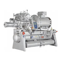
Johnson Controls SGC2317 Manual (171 pages)
Brand:
Johnson Controls
| Category:
Air Compressor
| Size: 4 MB
Table of Contents
Table of Contents
5
Introduction
11
Purpose
11
Main Users
11
Compressor Name, Sabroe/Frick
11
Amendments to the Manual
12
Manufacturer's Information
12
Safety Precaution Definitions Used in this Manual
13
Requirements for Competent Persons
13
Signs and Warnings
14
Main Users
14
Identification of Johnson Controls Denmark Equipment
14
Compressor Name Plate
15
Compressor Name Plate - ATEX
16
Labelling of Explosion-Proof Equipment
17
Vessel Name Plate
18
Unit/Pipe System Name Plate
19
Signs
21
Safety Precautions
22
Areas of Application
22
Application of the Screw Compressor
22
Application of Combustion Engines
22
Safety Precautions
23
General Precautions
23
Work Area Safety
23
During Operation
23
Safety During Maintenance and Service
24
Electrical Installations
25
Power Supply
25
Lubricating Oils
26
Refrigerants
26
Purging a Refrigeration Plant
26
F-Gas Regulation (Fluorinated Greenhouse Gases)
27
First Aid for Accidents with Ammonia
29
First Aid for Accidents with HFC/HCFC
30
Protecting the Operator as Well as the Environment
31
Technical Description
34
Description of the Screw Compressor
34
Marine Application
36
Description of Main Components and Systems
37
Control System
37
Compressor
38
Variable Speed Drive (VSD)
39
Compressor Lubrication System
40
Oil Injection Valve
40
No Pump Oil System
41
Demand Pump Oil System
41
Flow Security
41
Compressor Oil Separation System
41
Automatic Oil Return Valve
44
External Oil Filter
45
Unit with Double Oil Filter
46
Compressor Hydraulic System
46
Compressor Oil Cooling Systems
48
Suction Check Valve By-Pass
49
Requirements for Ambient Temperatures and Humidity
51
Oil Carry-Over to Plant
52
Selecting Lubricating Oil for Sabroe Screw Compressors
53
Oil Charge
53
Heating Rod Element for Oil Heating, Pos. 30
53
Oil Level Switch
54
Cold-Start System
54
Compressor Protecting System, Pos. 220 and 221
56
Oil Cooling System and General Piping Layout
57
Liquid Injection Oil Cooling
57
Thermosyphon Oil Cooling
59
Water-Cooled Oil Cooling
61
Connection to Alfanova Oil Cooler
62
KRACHT Oil Pump
63
Economiser, High-Stage (Optional)
64
General Piping Diagram
68
Key to Piping Diagram
71
Instrumentation
73
Physical and Connection Data
75
Physical Data
75
Allowable Flange Loads
76
Mounting of Suction Isolation Valve
77
Connection Data
78
Connections to Compressor Unit
78
Electrical Connections
84
List of Components
85
Technical Data
87
Data for Compressor Units
87
Other Data
88
Planning the Machine Room
89
Minimum Compressor Flow at 3550 Rpm
90
Operating Limits
91
Selecting Electric Motor
92
Motor Dimension
92
Motor Selection and Starting Torque
93
Motor/Compressor Torque
94
Direction of Rotation
95
Emergency Stop
95
Other Emergency Stop Requirements
95
Noise Data
96
Noise Data for SAB 193-233-283
96
Vibrations and Test Pressure Levels
97
Vibration Data for Compressors (All Compressor Types)
97
Test Pressure Levels for Standard Compressors and Components
99
Installation Instructions
100
Installation
100
Safety Precautions
100
Installation Data
100
Installation and First Start-Up Procedure
100
Installation Drawings
100
Personnel Requirements
101
Preparing the Installation
101
Tools and Accessories
101
Safety Equipment
101
Local Regulations
101
Preparing the Mounting Site
101
Space Requirements
102
Lifting and Loading Instructions
102
Unpacking and Inspection
102
Disposal of Non-Reusable Materials
102
Moving the Equipment to the Mounting Site
102
Alignment of Compressor and Unit
103
Alignment of Unit against Foundation
103
Alignment of Compressor and Motor
103
Laying the Unit Foundation
106
Mounting Directly on the Foundation
106
Mass Damping between Unit and Building
107
Damping Using Vibration Dampers
107
VSD Equipment
110
Calculation of Centre of Gravity, Support Reactions and Tipping Angle
112
Sab 193 S
113
Sab 193 L
113
Sab 233 S
116
Sab 233 L
116
Sab 233 E
116
Sab 283 S
116
Sab 283 L
117
Sab 283
117
Instruction for Mounting of Coupling
120
BPU Coupling Installation Procedure
121
Piping Connections
123
Connecting Electricity Supply
124
Pressure Testing
125
Evacuation of the Refrigeration Plant
126
Oil Charging
126
Final Installation Check
127
Components
128
Unisab III
129
Settings
130
Control System
130
Operating Instructions
131
Maintenance Instructions
132
Safety Precautions
132
Maintenance of Compressor Unit
132
Stopping Routine
133
Long-Term Storage
133
Visual Inspection
135
Measures to be Taken
135
General Rules for Use of Lubricating Oil in Refrigeration Compressors
137
Assessing the Oil
137
Visual Assessment
138
Analytical Evaluation
138
Analysing the Oil
138
Charging Compressor with Lubricating Oil
139
Oil Charge
142
Motor
143
Faultfinding Instructions
144
How to Carry out Faultfinding
144
Troubleshooting
145
Service Instructions
150
Transport Instructions
151
Safety Precautions
151
Transport Data
152
Personnel Requirements
152
Handling of Compressor and Unit
152
Loading Instructions
153
Preparations before Lifting
153
Loading
153
Transport Instructions
154
Transport Regulations
154
Unpacking and Inspecting the Unit
154
Moving the Equipment to the Mounting Site
154
Storage
154
Commissioning Instructions
156
Safety Precautions
156
Preparations for Commissioning
156
Preparations on the Mounting Site
157
Evacuation and Charging of Refrigerant
157
Start-Up
158
Commissioning Set
158
Commissioning Checklist
159
Spare Parts List
160
Spare Parts Drawings
161
Final Disposal
162
Safety Precautions
162
Waste Disposal
162
Appendices
163
Index
164
Advertisement
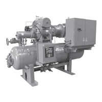
Johnson Controls SGC2317 Installation Operation & Maintenance (68 pages)
ROTARY SCREW COMPRESSOR UNITS
Brand:
Johnson Controls
| Category:
Air Compressor
| Size: 5 MB
Table of Contents
Table of Contents
2
Preface
3
Design.limitations
3
Job.inspection
3
Transit.damage.claims
3
Compressor.and.unit.identification
3
Compressor.identification
4
Installation
5
Foundation
5
Rigging.and.handling
5
Skid.removal
5
Checking Motor/Compress or Rota Tion
6
Compressor/Motor Coupling Installation
6
Bp.series.coupling.data.table
6
Oil.pump.coupling
7
Holding.charge.and.storage
7
Oil.charge
7
Oil.heater(S)
7
Oil.filter(S)
7
Suction.isolation.valve.mounting
8
Thermosyphon.oil.cooling
8
Liquid.injection.oil.cooling.(Optional)
9
Liquid.line.sizes/Receiver.volume
9
Water-Cooled Oil Cooling (Option Al)
9
Economizer.-.High.stage.(Optional)
10
Economizer.load.balancing
11
Electrical
11
Motor.starter.package
12
Current.transformer.(Ct).Ratios
13
Mini Mum Burden Ratings
13
Control.power.regulator
13
Operation
14
Operation.and.start-UP.INSTRUCTIONS
14
Sgc.compressor
14
Compressor.lubrication.system
14
No Pump Oil System
14
Demand.pump.oil.system
15
Compressor.oil.separation.system
15
Cold-Start.system
15
Compressor.hydraulic.system
16
Volume.ratio.control
16
Compressor.oil.cooling.systems
16
Single-Port.liquid.injection
17
Dual-Port.liquid.injection
17
Quantum Lx.ez-Cool Ez-Cool .Liquid.injection Injection Adjustment Procedure
18
Operation of Danfoss Liquid Injection Valve
19
Suction.check.valve.bypass
22
Low.ambient.operation
22
Suction Check Valve Power Assist Kit
22
Balance.piston.pressure.regulator
22
Initial.start-Up
23
Initial.start-Up.procedure
23
Normal.start-Up.procedure
23
Maintenance
24
Compressor.shutdown.and.start-UP
24
General Instructions for Replacing Compressor Unit Components
24
General.information
24
General.maintenance
24
Normal.maintenance.operations
24
Oil.filter.(Of-1).Main.single/Dual
25
Strainer.-.Demand.oil.pump
25
Strainer.-.Liquid.injection
25
Changing.oil
26
Coalescer.filter.element(S)
26
Demand.pump.disassembly
27
Demand.pump.assembly
28
Installation.of.carbon.graphite.bushings
29
Thrust.bearing.adjustment
29
Troubleshooting.the.demand.pump
29
Preventative.maintenance
30
Recommended.maintenance.program
30
Vibration.analysis
30
Maintenance.schedule
31
Oil.quality.and.analysis
31
Grease.compatibility
32
Motor.bearings
32
Nlgi.grease.compatibility.chart
32
Oil.sampling.procedure
32
Operating.log
32
ABNORMAL OPERATION ANALYSIS and CORRECTION
33
Troubleshooting.guide
33
Servicing.the.cold-Start.valve
34
Pressure.transducers.-.Replacement
35
Pressure.transducers.-.Testing
35
Capacity.linear.transmitter.-.Slide.valve
36
Temperature.sensor
36
Volume Ratio Control Transmitter - Slide Stop
36
Oil.level.transmitter
37
Troubleshooting.the.rwf.II.compressor
38
The.oil.separation.system
38
The.hydraulic.system
39
The.demand.pump.system
40
Motor.and.bare.compressor.replacement
40
Shutdown.due.to.improper.oil.pressure
40
Compressor.port.locations
41
P.&.I.diagram
49
Proper Installation of Electronic Equipment in an Industrial Environment
52
Forms
57
Advertisement
Related Products
Johnson Controls SGC2313
Johnson Controls SGC 2321
Johnson Controls SGC 2813
Johnson Controls SGC 2817
Johnson Controls SGC 2821
Johnson Controls SGC 2824
Johnson Controls SGCH 3511
Johnson Controls SGCB 3511
Johnson Controls SGCB 3515
Johnson Controls SGCB 3519
Johnson Controls Categories
Controller
Air Conditioner
Thermostat
Control Unit
Irrigation System
More Johnson Controls Manuals
Login
Sign In
OR
Sign in with Facebook
Sign in with Google
Upload manual
Upload from disk
Upload from URL