Table of Contents
Advertisement
Quick Links
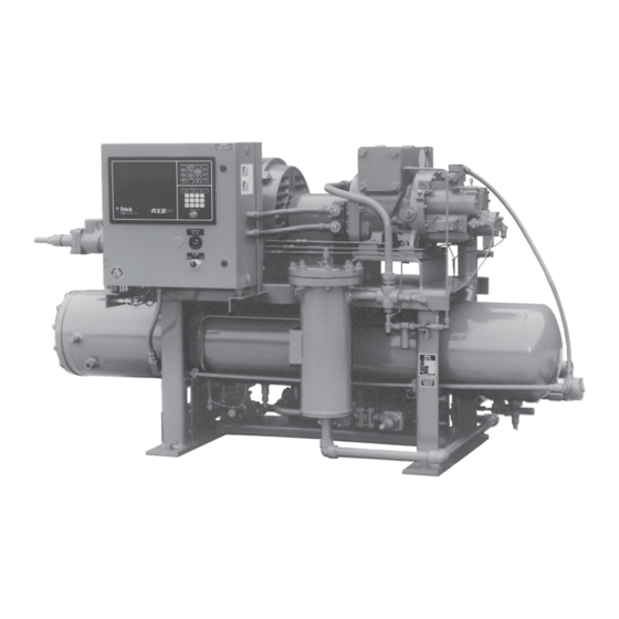
ROTARY SCREW COMPRESSOR UNITS
MICROPROCESSOR CONTROL
THIS MANUAL CONTAINS RIGGING, ASSEMBLY, START-UP,
AND MAINTENANCE INSTRUCTIONS. READ THOROUGHLY
BEFORE BEGINNING INSTALLATION. FAILURE TO FOLLOW THESE
INSTRUCTIONS MAY RESULT IN PERSONAL INJURY OR DEATH,
DAMAGE TO THE UNIT, OR IMPROPER OPERATION.
Please check www.johnsoncontrols.com/frick for the latest version of this publication.
Form 070.101-IOM (JAN 2013)
INSTALLATION - OPERATION - MAINTENANCE
File:
Replaces:
Dist:
WITH
ALL REFRIGERANTS
SERVICE MANUAL - Section 70
070.101-IOM (JAN 2000)
3, 3a, 3b, 3c
Advertisement
Table of Contents
Troubleshooting

Related Manuals for Johnson Controls Frick RXB Plus 12


Summary of Contents for Johnson Controls Frick RXB Plus 12
- Page 1 Form 070.101-IOM (JAN 2013) INSTALLATION - OPERATION - MAINTENANCE File: SERVICE MANUAL - Section 70 Replaces: 070.101-IOM (JAN 2000) Dist: 3, 3a, 3b, 3c ROTARY SCREW COMPRESSOR UNITS WITH MICROPROCESSOR CONTROL ALL REFRIGERANTS THIS MANUAL CONTAINS RIGGING, ASSEMBLY, START-UP, AND MAINTENANCE INSTRUCTIONS. READ THOROUGHLY BEFORE BEGINNING INSTALLATION.
-
Page 2: Table Of Contents
070.101-IOM (JAN 13) RXB PLUS ROTARY SCREW COMPRESSOR UNITS Page 2 INSTALLATION - OPERATION - MAINTENANCE TABLE OF CONTENTS GENERAL INFORMATION Prestart.Checklist............. 34 Preface................3 Initial.Start-up.Procedure..........35 Design.Limitations.............. 3 Normal.Start-up.Procedure..........35 Job.Inspection..............3 Restarting.Unit.After.Power.Failure........35 Transit.Damage.Claims............3 MAINTENANCE Compressor/Unit.Identification........... -
Page 3: Preface
NOTE: When inquiring about the compres sor or unit, or A.refrigeration.compressor.is.a.VAPOR.PUMP..To.be.certain. ordering repair parts, provide the MODEL, SERIAL, and that.it.is.not.being.subjected.to.liquid.refriger. a nt.carryover,.it. Johnson Controls-FRICK SALES ORDER NUMBERS is.necessary.that.refriger. a nt.controls.are.carefully.selected. from these data plates. and.in.good.operating.condition;.the.piping.is.properly.sized. and.traps,.if.necessary,.are.correct. l y.arranged;.the.suction. line. has. an. accumulator. or. slugging. protec. t ion;. that. load. - Page 4 070.101-IOM (JAN 13) RXB PLUS ROTARY SCREW COMPRESSOR UNITS Page 4 INSTALLATION - OPERATION - MAINTENANCE COMPRESSOR IDENTIFICATION Each.compressor.has.an.identification.data.plate.(see.below),. containing.compressor.model.and.serial.number.mounted.on. the.compressor.body.. COMPRESSOR DATA PLATE Rotary.screw.compressor.serial.numbers.are.defined.by.the. following.information: EXAMPLE:.10240A90000015Z GLOBAL ADDITIONAL PLANT DECADE MONTH YEAR SEQ NO. REMARKS 1024 0000015 Month:.A.=.JAN,.B.=.FEB,.C.=.MAR,.D.=.APR,.E.=.MAY,. F.=.JUN,.G.=.JUL,.H.=.AUG,.K.=.SEP,.L.=.OCT,.M.=.NOV,. N.=.DEC.
-
Page 5: Installation
RXB PLUS ROTARY SCREW COMPRESSOR UNITS 070.101-IOM (JAN 13) INSTALLATION Page 5 Installation ALLOWABLE FLANGE LOADS NOZ. MOMENTS (ft-lbf) LOAD (lbf) FOUNDATION SIZE AXIAL VERT. LAT. AXIAL VERT. LAT. Each.RXB PLUS.Rotary.Screw.Compressor.Unit.is.shipped. mounted.on.a.wood.skid.which.must.be.removed.prior.to.unit. installation...CAUTION: Allow space for servicing both ends . 1.25. . -
Page 6: Skid.removal
070.101-IOM (JAN 13) RXB PLUS ROTARY SCREW COMPRESSOR UNITS Page 6 INSTALLATION 1..Inspect.the.shaft.of.the.motor.and.compressor.to.ensure. that.no.nicks,.grease,.or.foreign.matter.is.present. 2..Inspect.the.bores.in.the.coupling.hubs.to.make.sure.that. they.are.free.of.burrs,.dirt,.and.grit. 3..Check.that.the.keys.fit.the.hubs.and.shafts.properly. CH COUPLING – The.T.B..Woods.Elastomeric.CH.Coupling. is. used. in. most. applications.. It. consists. of. two. drive. hubs. and.a.loose,.gear-type.Hytrel.Drive.Spacer..The.split.hub.is. clamped.to.the.shaft.by.tightening.the.clamp.screws..Torque. is.transmitted.from.the.motor.through.the.elastomeric.gear. which.floats.freely.between.the.hubs..Install.as.follows: Figure 2 - Alternative Lifting Method IT IS MANDATORY THAT THE COU- The.unit.can.be.moved.with.a.forklift.by.forking.under.the.skid,. -
Page 7: Coupling.alignment.procedure
RXB PLUS ROTARY SCREW COMPRESSOR UNITS 070.101-IOM (JAN 13) INSTALLATION Page 7 COUPLING ALIGNMENT PROCEDURE The.life.of.the.compressor.shaft.seal.and.bearings,.as.well. as.the.life.of.the.motor.bearings,.is.dependent.upon.proper. coupling.alignment..Couplings.may.be.aligned.at.the.factory. but. realignment. MUST ALWAYS. be. done. on. the. job. site. after.the.unit.is.securely.mounted.on.its.founda. t ion..Initial. alignment. must. be. made. prior. to. start-up. and. rechecked. after.a.few.hours.of.operation..Final.(HOT).field.alignment. - Page 8 070.101-IOM (JAN 13) RXB PLUS ROTARY SCREW COMPRESSOR UNITS Page 8 INSTALLATION PARALLEL ALIGNMENT 6. To.check.parallel.alignment,.as.shown.in.Figure.7,.reposi- tion.dial.indicator.so.the.stem.is.in.contact.with.the.rim.of.the. compressor.hub,.as.shown.in.Figure.8. Check.the.dial.indicator.to.be.sure.that.the.indicator.stem.is. slightly.loaded.so.as.to.allow.movement.in.both.directions. 7. Check.parallel.height.misalignment.by.setting.dial.indica- tor.at.zero.when.viewed.at.the.12.o’clock.position..Rotate. both.coupling.hubs.together.180 .(6.o’clock.position)..At.this. position.the.dial.indicator.will.show.TWICE.the.amount.of. parallel.height.misalignment... 8. Loosen.motor.anchor.bolts.and.add.or.remove.shims.under. the.four.motor.feet.until.parallel.height.misalignment.is.within. Figure 7 - Parallel Misalignment specified.tolerance.when.anchor.bolts.are.retightened. CARE MUST BE USED WHEN COR- RECTING FOR PARALLEL MIS- ALIGNMENT TO ENSURE THAT THE AXIAL SPACING AND ANGULAR MISALIGNMENT...
-
Page 9: Hot.alignment.of.compressor/Motor
RXB PLUS ROTARY SCREW COMPRESSOR UNITS 070.101-IOM (JAN 13) INSTALLATION Page 9 HOT ALIGNMENT OF COMPRESSOR/MOTOR Use of filter elements other than Frick must be approved in writing Hot.alignments.can.only.be.made.after.the.unit.has.oper- by Frick engineering or warranty ated.for.several.hours.and.all.components.are.at.operating. claim may be denied. temperatures. The.oil.charge.shipped.with.the.unit.is.the.best.suited.lubri- cant.for.the.conditions.specified.at.the.time.of.purchase..If. -
Page 10: Liquid.injection.oil.cooling
070.101-IOM (JAN 13) RXB PLUS ROTARY SCREW COMPRESSOR UNITS Page 10 INSTALLATION LIQUID INJECTION OIL COOLING The.liquid.injection.system.provided.on.the.unit.is.self-con- tained.but.requires.the.connection.of.the.liquid.line.sized.as. shown.in.the.table.and.careful.insertion.of.the.expansion.valve. bulb.into.the.thermowell.provided.in.the.separator..High.pres- sure.gas.is.connected.through.the.regulator.to.the.external. port.on.the.liquid.injection.valve.to.control.oil.temperature.. Refer.to.the.liquid.injection.piping.diagram. NOTE: For booster applications, the high pressure gas connection must be taken from a high side source (high- stage compressor discharge). -
Page 11: Thermosyphon.oil.cooling
RXB PLUS ROTARY SCREW COMPRESSOR UNITS 070.101-IOM (JAN 13) INSTALLATION Page 11 the.chamber.provided.on.the.oil.outlet.connection..Determine. that.sustains.a.flow.condi. t ion.to.the.oil.cooler..This.relation- ship.involves: the.size.of.the.water-cooled.oil.cooler.supplied.with.the.unit,. then.refer.to.table.for.the.water.connec. t ion.size.and.water. 1..Liquid.height.above.the.cooler. flow.range.(GPM)..The water supply must be sufficient to 2..Oil.heat.of.rejection. meet the required flow. 3..Cooler.size.and.piping.pressure.drops. It.is.imperative.that.the.condition.of.cooling.water.and.closed. loop. fluids. be. analyzed. and. maintained. regularly. and. as. necessary.to.prevent.corrosion.of.heat.exchanger.surfaces.. -
Page 12: Economizer.-.High.stage
070.101-IOM (JAN 13) RXB PLUS ROTARY SCREW COMPRESSOR UNITS Page 12 INSTALLATION Extra caution should be used when shell. side. of. the. oil. cooler. which. the. installing. contractor. servicing an oil separator with this should.pipe.into.house.safety.systems.designated.suitable. arrangement. If the oil cooler is for.oil.relief. -
Page 13: Electrical
RXB PLUS ROTARY SCREW COMPRESSOR UNITS 070.101-IOM (JAN 13) INSTALLATION Page 13 pressure..In.the.case.of.a.flash.vessel,.there.is.no.need.for. the.redundancy.of.a.back-pressure.regulating.valve.on.the. SUCTION vessel.and.each.of.the.multiple.compressors..Omit.the.BPR. valve.on.the.flash.economizer.vessel.and.use.one.on.each. INTERMEDIATE PRESSURE GAS TO COMPRESSOR compressor,.as.shown.in.Figure.18. HV-2 ECONOMIZER ELECTRICAL COOLER HIGH PRESSURE NOTE: Before proceeding with electrical installation, SUBCOOLED LIQUID HIGH PRESSURE read the instructions in the section “Proper Installation LIQUID TO of Elec tronic Equip ment in an Industrial Environment”. -
Page 14: Motor.starter.package
070.101-IOM (JAN 13) RXB PLUS ROTARY SCREW COMPRESSOR UNITS Page 14 INSTALLATION MOTOR STARTER PACKAGE CURRENT TRANSFORMER (CT) RATIOS The.CT.ratio.for.various.motor.sizes.(with.a.5.amp..second- Motor.starter.and.interlock.wiring.requirements.are.shown.in. ary).is.given.in.the.following.table: the.wiring.diagram,.above..All.the.equipment.shown.is.sup- plied.by.the.installer.unless.a.starter.package.is.pur. c hased. VOLTAGE from.Frick...Starter.packages.should.consist.of: 2300 4160 NOTE: When compressor mo tor vol tage is dif fer ent from 100:5 100:5 100:5... -
Page 15: Operation
RXB PLUS ROTARY SCREW COMPRESSOR UNITS 070.101-IOM (JAN 13) OPERATION Page 15 Operation OPERATION and START-UP INSTRUCTIONS GENERAL INFORMATION The.information.in.this.section.of.the.manual.provides.the. The.Frick.RXB.PLUS.Rotary.Screw.Compressor.Unit.is.an. logical. step-by-step. instructions. to. properly. start. up. and. integrated.system.consisting.of.six.major.subsystems: operate.the.RXB.PLUS.Rotary.Screw.Compressor.Unit. 1..Microprocessor.Control.Panel 2..Compressor THE FOLLOWING SUBSECTIONS MUST BE READ AND 3..Compressor.Lubrication.System UNDERSTOOD BEFORE ATTEMPTING TO START OR 4..Compressor.Oil.Separation.System... -
Page 16: Keys.and.key.functions
070.101-IOM (JAN 13) RXB PLUS ROTARY SCREW COMPRESSOR UNITS Page 16 OPERATION KEYS AND KEY FUNCTIONS 1.. Operating.displays . 2.. Setpoints.displays NOTE: The microprocessor will automatically return to . 3...Annunciator.displays the main operating display after 60 seconds of keybo ard . - Page 17 RXB PLUS ROTARY SCREW COMPRESSOR UNITS 070.101-IOM (JAN 13) OPERATION Page 17 pressed,. automatic. (AUTO. MODE). when. Auto. Cycle. has. . SETPOINTS.PAGE.1B been.activated,.remote.(RMT.MODE).when.the.[REMOTE]. key.has.been.pressed,.or.off.(OFF.MODE). . Dead.Band--[/./#] . Prop..Band--[/./.%] RECYCLE DELAY.-.A.Recycle.Delay.message.indicates.that. . Cycle.Time--[/./.sec] the.compressor.has.started.and.has.shut.down.within.the. time.delay.setpoint.period..The.Recycle.Delay.will.prevent. . LOW.%.FLA---[/././.%] the. compressor. from. starting. until. the. delay. time. expires. and.is.intended.to.prevent.damage.to.the.com.
-
Page 18: To.change.the.adjustable.setpoints
070.101-IOM (JAN 13) RXB PLUS ROTARY SCREW COMPRESSOR UNITS Page 18 OPERATION SETPOINTS DISPLAY, Page 1B: AUX 1.and.AUX 2.-.May.be.configured.for.either.an.alarm.or. shutdown.and.with.either.a.normally.closed.(NC).or.normally. Dead Band -.This.is.a.+.(plus).or.-.(minus).value.above.or. open.(NO).contact. below.the.setpoint.at.which.the.compressor..will.neither.load. TO CHANGE THE ADJUSTABLE SETPOINTS: nor.unload..A.dead.band.of.1.is.the.default.value..It.is..adjust- able.between..5.lb.to.5.lb.in.increments.of..5..The.[Step] key. Adjustable. Setpoints. are. stored. in. RAM. (random. access. is.used.to.select.this.setpoint;.then.press.the.[Change] key. - Page 19 RXB PLUS ROTARY SCREW COMPRESSOR UNITS 070.101-IOM (JAN 13) OPERATION Page 19 ANNUNCIATOR DISPLAY * The.High.Discharge.Pressure.Cutout.should.be.set.at.90%. of.the.setting.of.the.lowest.high.side.relief.valve..The.High. Discharge.Pressure.Alarm.should.be.set.10.PSIG.lower.than. . ANNUNCIATOR:.PG-01.Thu.03-01-89.15:33:36.. the.Cutout. . (Use.STEP.key.to.advance.PAGE)..High.Press..Cutout. *********************.. The.Capacity.Control.setpoint.should.be.the.equi. v alent.of. . High.Press..Alarm. ********************* the.normal.suction.condition. FIXED SETPOINTS: ANNUNCIATOR:.PG-02.Thu.03-01-89.15:33:36.. . (Use.STEP.key.to.advance.PAGE)..Fixed.setpoints.define.the.limits.of.acceptable.compressor. . Low.Press..Cutout. *********************..
- Page 20 070.101-IOM (JAN 13) RXB PLUS ROTARY SCREW COMPRESSOR UNITS Page 20 OPERATION Compressor Differential Cutout - The. differential. cutout. . SHUTDOWN.RECORD.P2.Thu.03-01-89.15:33:36 has.been.lowered.from.55.lb.to.25.lb..Cutout.will.occur.after. .. Low..Temp.Cutout. ********************* five.minutes...To.allow.operation.at.low.differential.pressures,. . Disch..Temp.Cutout. ********************* the.micro.will.take.the.following.steps: . Disch..Temp.Cutout. ********************* A..Force.unload.the.compressor.to.50%.and.display.an.“F. Unload”.when.the.oil.pressure.is.within.10.lb.of.the.main.oil. The.Shutdown.Record.display.keeps.a.record.of.the.last.six. injection.port.pressure.and.the.slide.valve.position.is.greater. shutdowns.(cutouts)..This.information.will.help.troubleshoot. than.50%. persistent.operational.problems..The.most.recent.cutout.will. appear.on.the.top.line.of.page.1.of.the.display.with.the.old- B.
- Page 21 RXB PLUS ROTARY SCREW COMPRESSOR UNITS 070.101-IOM (JAN 13) OPERATION Page 21 AUTO CYCLE DISPLAY * unauthorized.tam. p ering.with.the.various.adjustable.set. p oints.. When.enabled,.the.microprocessor.keyboard.is.fully.opera- tive.and.the.security.lockout.is.not.in.ef. f ect..When.disabled,. . AUTO.CYCLE. Compressor.Start.---[20.0.g.].. the.keyboard.is.rendered.partially.nonfunctional..All.displays. . F1.To.Exit. Compressor.Stop.---[18.0.hg].. will.still.be.accessible.through.the.keyboard..If.any.attempt. . Suct.Press.. Min..Cap..Control. - ---[050%]..is. made. to. enter. new. adjustable. set. p oints,. how. e ver,. the. .
-
Page 22: Temperature-Pressure.control.program
070.101-IOM (JAN 13) RXB PLUS ROTARY SCREW COMPRESSOR UNITS Page 22 OPERATION TEMPERATURE-PRESSURE CONTROL SETPOINTS DISPLAY, Page 3* PROGRAM (OPTION) . SETPOINTS.PAGE.3. ID=[02].[04-09-90].. NOTE: The following displays are provided only when offset-act. Mon..[01:00:18].. the Temperature-Pressure Control Program option has . Sup.Heat-Alarm-10F-no. Baud-[19200].. - Page 23 RXB PLUS ROTARY SCREW COMPRESSOR UNITS 070.101-IOM (JAN 13) OPERATION Page 23 TEMPERATURE-PRESSURE CONTROL MIN SV -.Minimum.Slide.Valve.Posi. t ion,.shown.as.a.percent- age,.will.limit.the.slide.valve.position.to.the.displayed.setpoint. PROGRAM (OPTION) (continued) ACTIVE -. Indicates. whether. Auto. Cycle. is. active. or. not.. PRESS SETPOINT - The.capacity-control.setpoint.is.used. Press.the.[CHANGE].key.while.at.this.setpoint.to.change. when.in.the.Setback.mode.and.Pressure.is.selected.as.the. the.status..Upon.deactiva. t ion,.the.compressor.will.return.to. capacity.control.desired.
-
Page 24: Lead-Lag Option
070.101-IOM (JAN 13) RXB PLUS ROTARY SCREW COMPRESSOR UNITS Page 24 OPERATION LEAD-LAG OPTION If the load falls: The. lead. compressor. will. stop. when. its. “STOP”. setpoint. is. reached. for. the. amount. of. time. selected. for. the.“TIME”. The. lead-lag. compressor. sequencing. option. provides. the. setpoint. -
Page 25: How.the.microprocessor.works.-.Summary
RXB PLUS ROTARY SCREW COMPRESSOR UNITS 070.101-IOM (JAN 13) OPERATION Page 25 LEAD-LAG OPTION (continued) a.solid.state.out. p ut.device.capable.of.handling.control.volt- age.and.the.instruc. t ion.is.executed..In.some.cases,.such. as.load.and.unload.instructions,.the.computer.dis. p lays.the. TYPICAL LEAD-LAG WIRING instruction.on.the.Operating.display.with.an.L.(load).or.U. (unload).symbol.at.the.same.time.as.the.appropriate.output. is.energized. If.the.microprocessor.receives.information.that.indicates.an. abnormal.operating.condition.has.been.reached.or.is.present,. it.will.generate.one.or.more.of.the.following.instructions: 1..If.a.subsystem.on.the.compressor.unit,.such.as.the.oil. heater(s). or. liquid. injection,. can. correct. the. problem,. the. microprocessor.will.energize.or.de-energize.this.system. -
Page 26: Multiple.compressor.sequencing
070.101-IOM (JAN 13) RXB PLUS ROTARY SCREW COMPRESSOR UNITS Page 26 OPERATION AT 167°F. NOTE: If the operator makes an error by at tempting to start the compressor under condi tions outside safe The.microprocessor.instructs.the.compressor.motor.to.shut. normal operating conditions, the micropro cessor will down.and.displays.a.CUTOUT.indication.on.the.Operating. -
Page 27: Microprocessor.telecommunications
RXB PLUS ROTARY SCREW COMPRESSOR UNITS 070.101-IOM (JAN 13) OPERATION Page 27 MICROPROCESSOR OUTPUT DATA CODE NEUTRAL PROGRAMMABLE CONTROL OUTPUT A.3.5.KOHM,.10.watt.resistor.(RES).must. DATA CODE BIT 3 be.field.installed,.as.shown.below,.when. OUTPUT PROGRAMMABLE CONTROL DATA CODE BIT 2 the.120.VAC.outputs.of.the.RXB.PLUS.are. OUTPUT PROGRAMMABLE CONTROL driving.120.VAC.solid.state.input.devices. DATA CODE BIT 1 such.as.programmable.controllers. - Page 28 070.101-IOM (JAN 13) RXB PLUS ROTARY SCREW COMPRESSOR UNITS Page 28 OPERATION . COMPRESSOR.DISPLAY.SCREENS.COMMAND:..#01DXNN CHANGE.SETPOINTS.COMMAND:..#01C . #. Start.command.sequence. . #...Start.command.sequence. . 01..Compressor.ID.code. . 01. Compressor.ID.code. . D...Compressor.control.com. m and. . C. Change.setpoint.command. . xxx. New.setpoint. . X. =. O. Operating.display.(Page.1.&.2). .
- Page 29 RXB PLUS ROTARY SCREW COMPRESSOR UNITS 070.101-IOM (JAN 13) OPERATION Page 29 READ.INPUT/OUTPUT.COMMAND READ.FAILURES.COMMAND:.#01F . #. Start.command.sequence. . #01X . #. Start.command.sequence. . 01. Compressor.ID.Code. . 01. Compressor.ID.Code. . F. Read.Failures.command. . X. Read.Input/Output(s).command. . Returned.Answer: . Returned.Answer: A00000000000000000000000002 A10000011000000000100000001 .
-
Page 30: Rxb.compressor
070.101-IOM (JAN 13) RXB PLUS ROTARY SCREW COMPRESSOR UNITS Page 30 OPERATION RXB COMPRESSOR 3..Serves.to.remove.the.heat.of.compression.from.the.gas,. keeping.discharge.temperatures.low.and.minimizing.refriger- ant.or.oil.break. d own. The. Frick. RXB. rotary. screw. compressor. utilizes. mating,. asymmetrical-profile.helical.rotors.to.provide.a.continuous. 4..Fills.gas.leakage.paths.between.or.around.the.rotors.with. pulse-free.flow.of.refriger. a nt.vapor.and.is.designed.for.both. oil,.thus.greatly.reducing.gas.leakage.and.main. t ain. i ng.good. high.pressure.and.low.pressure.applications..The.compres. s or. compressor.per. -
Page 31: Compressor.hydraulic.system
RXB PLUS ROTARY SCREW COMPRESSOR UNITS 070.101-IOM (JAN 13) OPERATION Page 31 COMPRESSOR HYDRAULIC SYSTEM FUNCTIONAL CHECK OF THE COMPRESSOR VOLUME RATIO CONTROL (Vi) OPERATION The.compressor.hydraulic.system.moves.the.movable.slide. valve.(MSV).to.load.and.unload.the.compressor..It.also.moves. 1. Remove.the.slide.valve.potentiometer.cover.located.on. the.movable.slide.stop.(MSS).to.increase.or.de. c rease.the. the. outlet. end. of. the. compressor. and. secured. by. 4. cap. compressor’s.volume.ratio.(Vi). -
Page 32: Compressor.oil.cooling.systems
070.101-IOM (JAN 13) RXB PLUS ROTARY SCREW COMPRESSOR UNITS Page 32 OPERATION COMPRESSOR OIL COOLING SYSTEMS SINGLE-PORT LIQUID INJECTION The.RXB PLUS.unit.can.be.equipped.with.one.of.several. The.single-port.liquid.injection.system.is.designed.to.permit. systems.for.controlling.the.compressor.oil.tempera. t ure..They. liquid.refrigerant.injection.into.one.port.on.the.compressor. are. single. or. dual-port. liquid. injection,. thermo. s yphon. or. at.any.given.moment.and.operate.as.outlined. water-cooled. oil. coolers.. Each. system. is. automati. c ally. controlled,. -
Page 33: Dual-Port.liquid.injection
RXB PLUS ROTARY SCREW COMPRESSOR UNITS 070.101-IOM (JAN 13) OPERATION Page 33 DUAL-PORT LIQUID INJECTION LIQUID INJECTION ADJUSTMENT PROCEDURE The.dual-port.liquid.injection.system.is.designed.to.obtain. the.most.efficient.compressor.performance.at.high.and.low. 1..Close.vent.valve.(V4). compression.ratios.by.permitting.injection.of.liquid.refriger. a nt. into.one.of.two.ports.on.the.compressor. 2..Open.service.valve.(V5).until.ap. p roxi. m ately.80.PSIG.is. registered.at.the.Pressure.Indicator.(PI). The. dual-port. system. contains. all. the. components. of. the. single-port.system.with.the.addition.of.a.double-acting.sole- 3..Open.vent.valve.(V4).until.75.PSIG.is.registered.at.the. -
Page 34: Prestart.checklist
070.101-IOM (JAN 13) RXB PLUS ROTARY SCREW COMPRESSOR UNITS Page 34 OPERATION PRES TART CHECK LIST All.check.points.in.the.fol. l owing.list.must.be.com. p leted.before.placing.the.compressor.unit.in.operation..Only.when.the.checklist. is.completed.will.the.unit.be.ready.for.initial.start-up... CHECKPOINT Ammonia.Units:. Only.refrigerant.grade.Ammonia.as.specified.by.International.Institute.of.Ammonia.Refrigeration (IIAR).Bulletin.#.110,.Section.3.3.should.be.used.with.FRICK.equipment. Unit.pressure.test..Close.suction.and.discharge.service.valves,.and.isolation.valve.to.low.pressure.transducer. Introduce.pressure.to.unit.and.check.for.leaks...CAUTION: Do NOT exceed 80% of relief valve and/or 100% of the vessel’s design working pressure. Charge.unit.with.proper.amount.and.grade.of.oil..Oil.level.should.be.between.the.two sight.glasses.on.the.oil.separator. -
Page 35: Initial.start-Up.procedure
RXB PLUS ROTARY SCREW COMPRESSOR UNITS 070.101-IOM (JAN 13) OPERATION Page 35 INITIAL START-UP PROCEDURE Having.performed.the.checkpoints.on.the.prestart.check.list,. the.compressor.unit.is.ready.for.start-up...It.is.impor. t ant.that. an.adequate.refrigerant.load.be.available.to.load.test.the.unit. at.normal.operating.conditions..The.following.points.should. be.kept.in.mind.during.initial.start-up. 1.. On. start-up,. the. unit. should. be. operated. at. as. high. a. load.as.possible.for.3.hours..During.this.period,.adjust.liquid. injec. t ion.oil.cooling.if.applicable..If.the.unit.has.water-.cooled. oil.cooling,.adjust.the.water.control.valve.to.the.cooler..No. adjustment.is.required.for.thermosyphon.oil.cooling. 2.. -
Page 36: Maintenance
070.101-IOM (JAN 13) RXB PLUS ROTARY SCREW COMPRESSOR UNITS Page 36 MAINTENANCE MAINTENANCE 3. Open.suction,.discharge,.and.liquid.injection.service.valves. This.section.provides.instructions.for.normal.maintenance,. a. recommended. maintenance. program,. troubleshooting. and.remove.tags.. and.correction.guides,.typical.wiring.diagrams,.and.typical. 4.. Compressor. unit. is. ready. for. prestart. checks.. Refer. to. P.and.I.diagrams. PRESTART CHECKLIST. THIS SECTION MUST BE READ AND GENERAL INSTRUCTIONS FOR REPLACING UNDERSTOOD BEFORE ATTEMPT- ING TO PERFORM ANY MAINTE-... -
Page 37: Oil.filter,.Dual
RXB PLUS ROTARY SCREW COMPRESSOR UNITS 070.101-IOM (JAN 13) MAINTENANCE Page 37 OIL RETURN STRAINER 1..If.a.single.oil.filter.is.installed,.push.[STOP] key.to.shutdown. the.unit...Open.disconnect.switches.for.the.compressor.and. (if.applicable).oil.pump.motor.starters. The.unit.must.be.shut.down.and.equalized.to.atmospheric. pressure...NOTE: Recover or transfer all refrigerant vapor 2..Close.discharge.service.valve..SLOWLY.vent.the.sepa- in accordance with local ordinances before opening to rator.to.low-side.system.pressure.using.the.suction.check. atmosphere. valve.bypass..Close.suction.valve.and.suction.check.valve. bypass..NOTE: Recover or transfer all refrigerant vapor, 1..Remove.the.large.plug.from.the.bottom.of.the.strainer,. -
Page 38: Coalescer.filter.element
070.101-IOM (JAN 13) RXB PLUS ROTARY SCREW COMPRESSOR UNITS Page 38 MAINTENANCE 4..Close.the.service.valve.located.between.the.compressor. Shut.down.the.unit.when.changing.oil...At.the.same.time,. and.the.liquid.injection,.thermal.expansion.valve. all.oil.filter.cartridges.must.be.changed.and.all.oil.strainer. elements.removed.and.cleaned..The.procedure.is.as.follows: 5..Carefully.loosen.the.capscrews.securing.the.strainer.cover. to.the.strainer...Allow.pressure.to.relieve.slowly. 1..Push.[STOP].key.to.shut.. d own.the.unit. 6..When.all.entrapped.refrigerant.has.been.relieved,.care- 2.. Open. the. disconnect. switch. for. the. compressor. motor. fully.remove.the.loosened.capscrews.(as.liquid.refrigerant. starter.and.(if.applicable).oil.pump.motor.starter.. is. some. t imes. caught. in. the. strainer),. strain. e r. cover,. and. 3.. -
Page 39: Recommended.maintenance.program
RXB PLUS ROTARY SCREW COMPRESSOR UNITS 070.101-IOM (JAN 13) MAINTENANCE Page 39 RECOMMENDED MAINTENANCE PROGRAM 4..Vibration.readings.can.be.influenced.by.other.equipment. operating.in.the.vicinity.or.connected.to.the.same.piping.as. In.order.to.obtain.maximum.compressor.unit.perfor. m ance. the.unit. and.ensure.reliable.operation,.a.regular.main. t enance.pro- OIL QUALITY and ANALYSIS gram.should.be.followed. The. compressor. unit. should. be. checked. daily. for. leaks,. High.quality.refrigeration.oil.is.necessary.to.ensure.compres- abnormal.vibration,.noise,.and.proper.opera. t ion..A.daily.log. sor.longevity.and.reliability..Oil.quality.will.rapidly.deteriorate. -
Page 40: Maintenance.schedule
070.101-IOM (JAN 13) RXB PLUS ROTARY SCREW COMPRESSOR UNITS Page 40 MAINTENANCE MAINTENANCE SCHEDULE This.schedule.should.be.followed.to.ensure.trouble-free.operation.of.the.compressor.unit. HOURS OPERATION (MAXIMUM) MAINTENANCE CHANGE.OIL. As.directed.by.oil.analysis OIL.ANALYSIS. Then.every.6.months CHANGE.FILTERS CLEAN.OIL. STRAINERS CLEAN.LIQUID. STRAINERS CHANGE.COALESCERS CHECK.AND.CLEAN SUCTION.SCREEN CHECK.ALIGNMENT CHECK.COUPLING VIBRATION.ANALYSIS. Every.6.months,.more.frequently.if.levels.increase REPLACE.SEAL. When.leak.rate.exceeds.7.-.8.drops.per.minute... -
Page 41: Troubleshooting.guide
RXB PLUS ROTARY SCREW COMPRESSOR UNITS 070.101-IOM (JAN 13) MAINTENANCE Page 41 TROUBLESHOOTING GUIDE 3..Excessively.high.suction.superheat. 4. Excessively.high.discharge.pressure. Successful.problem.solving.requires.an.organ. i zed.ap. p roach. to. define. the. problem,. identify. the. cause,. and. make. the. 5..Inadequate.refrigerant.charge.or.low.receiv. e r.level. proper.correction. 6.. Excessively. high. or. low-temperature. coolant. to. the. oil. ABNORMAL OPERATION cooler. -
Page 42: Troubleshooting.the.microprocessor
070.101-IOM (JAN 13) RXB PLUS ROTARY SCREW COMPRESSOR UNITS Page 42 MAINTENANCE TROUBLESHOOTING The.control.system.of.the.RXB PLUS.compressor.con. s ists. of.a.120.volt.AC.(high.voltage).side.and.a.DC.(low.voltage). THE RXB PLUS MICROPROCESSOR side..The.120.volt.side.actuates.sole. n oids,.relays,.alarms,. and.other.electro. m echanical.functions..The.DC.side.operates. This. section. contains. information. on. troubleshooting. and. the.computer.and.its.various.sensors..The.micro. p roces. s or. making. - Page 43 RXB PLUS ROTARY SCREW COMPRESSOR UNITS 070.101-IOM (JAN 13) MAINTENANCE Page 43 TROUBLESHOOTING FRICK SBC MICROPROC ESSOR SYSTEM (Continued) SYMPTOM PROBABLE CAUSES and CORRECTIONS . SLIDE.VALVE.DOES.NOT.LOAD. Verify.that.the.Slide.Valve.is.in.the.AUTO.mode.and.that.capacity.control.is.calling.for.loading . and/or.UNLOAD. or.unloading.(AUTO.L.or.AUTO.U.will.appear.on.the.Operating.display). Output.2.controls.the.Slide.Valve.Load.Solenoid..If.120VAC.is.found.across.Wires.17.and.2,.the Slide.Valve.Load.Solenoid.should.be.energized..If.not,.the.solenoid.is.defective..If.120VAC.is.not found.when.the.LED.for.Output.2.is.on,.check.the.fuse.(FU2). Output.3.controls.the.Slide.Valve.Unload.Solenoid..If.120VAC.is.found.across.Wires.16.and.2,.the Slide.Valve.Unload.Solenoid.should.be.energized..If.not,.the.solenoid.is.defective..If.120VAC.is not.found.across.Wires.16.and.2.when.the.LED.for.Output.3.is.on,.check.the.fuse.(FU3). NOTE: Verify that the proper setpoint has been programmed into C.C. (Capacity Control) on the Adjustable Setpoints display.
- Page 44 070.101-IOM (JAN 13) RXB PLUS ROTARY SCREW COMPRESSOR UNITS Page 44 MAINTENANCE TROUBLESHOOTING FRICK SBC MICROPROC ESSOR SYSTEM (Continued) SYMPTOM PROBABLE CAUSES and CORRECTIONS . DISPLAY.SCREENS.DISPLAY. A.loose.or.improper.connection.between.the.displays.and.the.SBC.is.indicated...Remove.fuse . SCRAMBLED.PATTERN.OR. (2FU,.10.amp).for.15.seconds,.then.restore.to.reset.the.displays. . LIST.ALPHABET . OIL.PUMP.DOES.NOT.START. Verify.that.the.Oil.Pump.HAND-OFF-AUTO.switch.(1SS).is.in.the.AUTO.position.and . (Optional). that.the.Emergency.Stop.Button.is.not.depressed........................Output.11.controls.the.Oil.Pump.Starter.Relay.(3CR).when.in.the.AUTO.mode..If.HAND.is selected.on.1SS,.Output.11.will.not.have.any.effect.on.the.operation.of.the.oil.pump.starter.
-
Page 45: Eprom.memory.i/C.chip.replacement
RXB PLUS ROTARY SCREW COMPRESSOR UNITS 070.101-IOM (JAN 13) MAINTENANCE Page 45 EPROM MEMORY I/C CHIP REPLACEMENT OUTPUT FUSE REPLACEMENT 1. Shut.off.control.power. Microprocessor.EPROM.memory.I/C.chips.are.located.inside. the. microprocessor. console. on. the. SBC. board.. A. special. 2..Remove.the.microprocessor.console.cover. tool.is.required.to.remove.these.chips.to.lessen.the.chance. of.damaging.them.(See.Troubleshooting.The.Microproces- 3. Identify.the.faulty.fuse. sor)..The. procedure. to. replace. EPROM. memory. chips. is. outlined.below: 4. -
Page 46: Pressure.transducers.-.Replacement
070.101-IOM (JAN 13) RXB PLUS ROTARY SCREW COMPRESSOR UNITS Page 46 MAINTENANCE PRESSURE TRANSDUCERS - 2..Isolate.suction.transducer.PE-4.from.the.unit.and.open. it. to. atmosphere. using. valves. provided. at. the. transducer. REPLACEMENT manifold.Close. the. applicable. transducer. isolation. valve.. . NOTE: To change the discharge pressure transducer 1..Shut.off.control.power. -
Page 47: Volumizer.potentiometer.-.Replace/Adjust
RXB PLUS ROTARY SCREW COMPRESSOR UNITS 070.101-IOM (JAN 13) MAINTENANCE Page 47 SLIDE VALVE POSITION POTENTIOMETER BARE COMPRESSOR MOUNTING REPLACEMENT AND ADJUSTMENT The.following.procedure.is.required.only.when.a.bare.com- pressor.is.replaced.in.the.field. The.slide.valve.potentiometer.is.located.under.a.cover.on.the. right.side.of.the.compressor.(facing.shaft).at.the.inlet.end. 1..Thoroughly.clean.the.compressor.feet.and.mounting.pads. of.burrs.and.other.foreign.matter.to.ensure.firm.seating.of. 1..Shut.off.control.power. the.compressor. 2..Remove.the.potentiometer.cover.and.gasket. 2..Clean.the.discharge.flange.surfaces.on.the.compres. s or. 3..Remove.the.potentiometer.and.mounting.bracket. and.separator. 4..Install.new.potentiometer.and.bracket. 3..Install.a.gasket.on.the.compressor.discharge.connec. t ion. of.the.separator. -
Page 48: Troubleshooting.the.rxb.plus: . Compressor
070.101-IOM (JAN 13) RXB PLUS ROTARY SCREW COMPRESSOR UNITS Page 48 MAINTENANCE TROUBLESHOOTING THE RWB II PLUS COMPRESSOR SYMPTOM PROBABLE CAUSES and CORRECTIONS . EXCESSIVE.NOISE.and.VIBRATION. Bearing.damage.or.excessive.wear...CONTACT.Frick.Factor.or.Frick. Coupling.loose.on.shaft...Tighten.coupling...Replace.if.damaged. Misalignment.between.motor.and.compressor...Realign.motor.and.compressor. Refrigerant.flood-back...Correct.system.problem. TROUBLESHOOTING THE OIL SEPARATOR SYMPTOM PROBABLE CAUSES and CORRECTIONS . GRADUAL.OIL.LOSS.WITH.AN.OIL. Maintaining.too.high.an.oil.level..Lower.level....... -
Page 49: Full-Time.pump.systems
RXB PLUS ROTARY SCREW COMPRESSOR UNITS 070.101-IOM (JAN 13) MAINTENANCE Page 49 TROUBLESHOOTING THE OIL PUMP SYSTEM SYMPTOM PROBABLE CAUSES and CORRECTIONS PUMP.WILL.NOT.PRODUCE.. Filter.cartridge.may.be.blocked...Check.PSID.across.filter..Replace.filter. . ENOUGH.OIL.PRESSURE . TO.START.COMPRESSOR. Strainer.may.be.blocked..Clean. Oil.pressure.regulator.set.too.low.or.stuck.open...Readjust.or.repair. Low.oil.level..Add.oil. Excessive.refrigerant.in.oil..Equalize.separator.to.a.lower.pressure. . OIL.PRESSURE.RAPIDLY.DROPS. Oil.pressure.regulating.valve.improperly.adjusted..Readjust.valve..Check.manual.system. . OFF.WHEN.COMPRESSOR.STARTS. Regulator.defective..Replace. Excessive.refrigerant.in.oil..Check.heaters. . OIL.PRESSURE.FLUCTUATES. Liquid.injection.overfeeding.or.refrigerant.carryover...Make.necessary.adjustments or.correc. -
Page 50: Thermal.expansion.valves
070.101-IOM (JAN 13) RXB PLUS ROTARY SCREW COMPRESSOR UNITS Page 50 MAINTENANCE THERMAL EXPANSION VALVES JORDAN TEMPERATURE REGULATOR VALVE (For low differential pressure applications) In.situations.where.system.load.conditions.increase.or.de- crease.over.extended.periods.of.time.and.the.liquid.injection. thermal.expansion.valve.is.not.adequate.for.the.new.condi- tions,.an.improvement.in.valve.perfor. m ance.may.be.achieved. by.increasing.or.decreasing.discharge.tube.size. NOTE: DO NOT ATTEMPT TO ADJUST SUPERHEAT ADJUSTMENT STEM ON BOTTOM OF VALVE IN AN EF- FORT TO CHANGE THE VALVE’S PERFORMANCE. -
Page 51: P.and.i.diagrams
RXB PLUS ROTARY SCREW COMPRESSOR UNITS 070.101-IOM (JAN 13) MAINTENANCE Page 51 P & I DIAGRAM, All Models WATER-COOLED OIL COOLER THERMOSYPHON OIL COOLER 1" AMOT VALVE (REMOVE TEMP. TO OIL ELEMENT BEFORE WELDING, REINSTALL SEPARATOR ELEMENT W/SENSING BULB IN "A" PORT) TO OIL FILTER FROM OIL SEPARATOR... - Page 52 070.101-IOM (JAN 13) RXB PLUS ROTARY SCREW COMPRESSOR UNITS Page 52 MAINTENANCE P & I DIAGRAM, Models 12, 15, & 19 w/Full-Lube Oil Pump LEGEND (Covers P & I diagrams pages 58 – 60) See page 59 for additional notes AUTO.CYCLE LTCO.
- Page 53 RXB PLUS ROTARY SCREW COMPRESSOR UNITS 070.101-IOM (JAN 13) MAINTENANCE Page 53 P & I DIAGRAM, Models 24, 30, 39, & 50 w/Full-Lube Oil Pump CONNECTION DESCRIPTION NOTES PRESSURE.TRANSDUCER.INDICATE:... 1. MAIN.OIL.SUPPLY 2. SLIDE.VALVE.POSITION . PE1. OIL.PRESSURE.(MAINIFOLD)..3. LOW.Vi.LIQUID.INJECTION . PE3. DISCHARGE.PRESSURE .
-
Page 54: Micro.component.placement.diagram
070.101-IOM (JAN 13) RXB PLUS ROTARY SCREW COMPRESSOR UNITS Page 54 MAINTENANCE MICRO COMPONENT PLACEMENT DIAGRAM... -
Page 55: Wiring.diagrams
RXB PLUS ROTARY SCREW COMPRESSOR UNITS 070.101-IOM (JAN 13) MAINTENANCE Page 55 SBC WIRING DIAGRAM RXB PLUS TELECOMMUNICATIONS COMPUTER TO MICROPROCESSOR WIRING DIAGRAM COMPUTER COMPRESSOR #1 COMPRESSOR #2 COMMUNICATIONS PORT: AC-422 PORT #1 PORT #1... - Page 56 070.101-IOM (JAN 13) RXB PLUS ROTARY SCREW COMPRESSOR UNITS Page 56 MAINTENANCE MICRO PANEL ASSEMBLY WIRING DIAGRAM CUSTOMER SUPPLIED 120 VAC CONTROL TRANSFORMER POWER SOURCE IS REQUIRED EARTH BUSBAR AT NEUTRAL ALL POWER SOURCES SHALL BE GROUNDED ON ONE SIDE POWER SOURCE -ISOLATED AND SEPARATED FROM OTHER INDUCTIVE LOADS SUCH AS LIGHTING CIRCUITS ALL NEUTRALS ENTERING...
- Page 57 RXB PLUS ROTARY SCREW COMPRESSOR UNITS 070.101-IOM (JAN 13) MAINTENANCE Page 57 MICRO PANEL ASSEMBLY WIRING DIAGRAM RXBELD2 NOTE A: IF COMPR. MOTOR STARTER IS A FRICK SUPPLIED STARTER OR CONFORMS TO FRICK STARTER SPECS, WIRE AS SHOWN ON LINE 60 ONLY. JUMP TERM 6 TO 36. IF 2CR IS USED AS A ISOLATED CONTACT, WIRE AS SHOWN BETWEEN THE HOT &...
- Page 58 070.101-IOM (JAN 13) RXB PLUS ROTARY SCREW COMPRESSOR UNITS Page 58 MAINTENANCE MICRO PANEL ASSEMBLY WIRING DIAGRAM C.T. MOUNTED IN STARTER OR MOTOR JUNCT. BOX (BY OTHERS) MOTOR CHANNEL 12 0-5 AMP AC AMPS SECONDARY 0-5 AMP AC MOTOR AMPS ONE PHASE SEE IOM MANUAL OF MOTOR...
- Page 59 RXB PLUS ROTARY SCREW COMPRESSOR UNITS 070.101-IOM (JAN 13) MAINTENANCE Page 59 MICRO PANEL ASSEMBLY WIRING DIAGRAM TEMPERATURE SENSOR WIRING TO BE #8760 BELDEN CABLE OR EQUAL. GROUND DRAIN WIRE AT PANEL GROUND ONLY. INSULATE AT PROBE END NOTE 2A: SPECIFICATIONS FOR TEMP .
-
Page 60: Proper Installation Of Electronic Equipment
070.101-IOM (JAN 13) RXB PLUS ROTARY SCREW COMPRESSOR UNITS Page 60 MAINTENANCE PROPER INSTALLATION OF ELECTRONIC EQUIPMENT IN AN INDUSTRIAL ENVIRONMENT In.today’s.refrigeration.plants,.electronic.controls.have.found. to.its.maximum.capacity,.the.voltage.dips.are.much.larger,. their.way.into.almost.every.aspect.of.refrigeration.control.. . and.the. potential.of. a. malfunction.is.very.high..If. the. wire. Electronic.controls.have.brought.to.the.industry.more.pre- is.sized.one.size.larger.than.required,.the.voltage.dips.are. cise.control,.improved.energy.savings,.and.operator.conve- smaller.than.in.a.fully.loaded.supply.wire.and.the.potential. niences..Electronic.control.devices.have.revolutionized.the. for.malfunction.is.much.lower..The.NEC.code.book.calls.for. way.refrigeration.plants.operate.today... specific.wire.sizes.to.be.used.based.on.current.draw..An.ex- ample.of.this.would.be.to.use.#14.gauge.wire.for.circuits.up. The. - Page 61 RXB PLUS ROTARY SCREW COMPRESSOR UNITS 070.101-IOM (JAN 13) MAINTENANCE Page 61 GROUNDING NEC.size.ratings.are.for.safety.purposes.and.not.necessarily. for.adequate.relaying.of.noise.(EMI).to.earth.ground.to.avoid. Grounding.is.the.most.important.factor.for.successful.opera- possible.interference.with.sensitive.equipment..Therefore.siz- tion.and.is.typically.the.most.overlooked...The.NEC.states.that. ing.this.conductor.1.–.2.sizes.larger.than.required.by.code. control.equipment.may.be.grounded.by.using.the.rigid.conduit. will.provide.better.transfer.of.this.noise.. as.a.conductor..This.worked.for.the.earlier.relay.systems,.but. it.is.in.no.way.acceptable.for.electronic.control.equipment.. Frick.requires.that.the.ground.conductor.meet.the.following. Conduit.is.made.of.steel.and.is.a.poor.conductor.relative.to.an. requirements.be:. insulated.stranded.copper.wire..Electronic.equipment.reacts. •. Stranded.Copper to.very.small.currents.and.must.have.a.proper.ground.in.order. to.operate.properly;.therefore,.stranded.copper.grounds.are. •. Insulated required.for.proper.operation.. •. One.size.larger.than.NEC.requirements.for.conventional. starters For.proper.operation,.the.control.power.ground.circuit.must. •. Two.sizes.larger.than.NEC.requirements.for.VFD.starters be.a.single.continuous.circuit.of.the.proper.sized.insulated.
- Page 62 All. national. and. local. codes. must. be. followed. for. conduit. An. example. of. this. would. be. the. installation. of. a. screw. with.regard.to.materials,.spacing.and.grounding..In.addition,. compressor.package.where.the.motor.voltage.is.480.volts. Johnson Controls-Frick requirements must be followed and.the.electronic.control.panel.power.is.120.volts..The.480. where they exceed or match national or local codes. Con- volt.circuit.must.be.run.from.the.motor.starter.to.the.motor.
- Page 63 RXB PLUS ROTARY SCREW COMPRESSOR UNITS 070.101-IOM (JAN 13) MAINTENANCE Page 63 Do.not.drill.into.an.electronic.control.panel.to.locate.conduit. Never run refrigerant tubing inside an electronic control panel. If.the.refrigerant.is.ammonia,.a.leak.will.totally.destroy. connections..You.are.probably.not.entering.the.panel.where. the.electronics. the.manufacturer.would.like.you.to.since.most.manufactur- ers.recommend.or.provide.prepunched.conduit.connections.. . If the electronic control panel has a starter built into the You.may.also.be.negating.the.NEMA.rating.of.the.enclosure.. same panel, be sure to run the higher voltage wires where Drilling.can.cause.metal.filings.to.land.on.the.electronics.and.
- Page 64 070.101-IOM (JAN 13) RXB PLUS ROTARY SCREW COMPRESSOR UNITS Page 64 MAINTENANCE COMMUNICATIONS UPS POWER AND QUANTUM LX PANELS ™ The. use. of. communications. such. as. serial. and. ethernet. Johnson. Controls,. Inc.. does. not. advise. nor. support. the. in. industrial. environments. are. commonplace..The. proper. use.of.uninterrupted.power.supply.systems.for.use.with.the.
-
Page 65: Operating Log
RXB PLUS ROTARY SCREW COMPRESSOR UNITS 070.101-IOM (JAN 13) MAINTENANCE Page 65 OPERATING LOG SHEET... - Page 68 Johnson Controls Supersedes: 070.101-IOM (2000-01) 100 CV Avenue Subject to change without notice Waynesboro, PA 17268-1206 USA Published in USA • GUI • 0113 PDF Phone: 717-762-2121 • FAX: 717-762-8624 www.johnsoncontrols.com/frick © 2013 Johnson Controls Inc. - ALL RIGHTS RESERVED...
Need help?
Do you have a question about the Frick RXB Plus 12 and is the answer not in the manual?
Questions and answers