Table of Contents
Advertisement
Quick Links
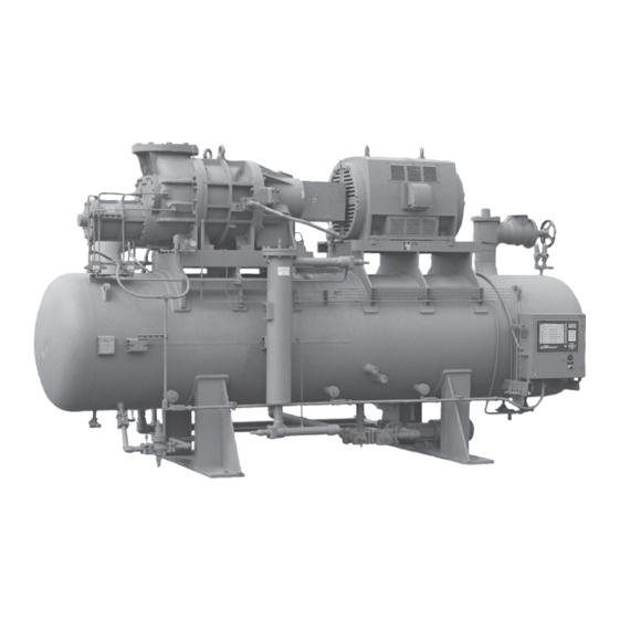
ROTARY SCREW COMPRESSOR UNITS
496 through 1080
THIS MANUAL CONTAINS RIGGING, ASSEMBLY, START-UP,
AND MAINTENANCE INSTRUCTIONS. READ THOROUGHLY
BEFORE BEGINNING INSTALLATION. FAILURE TO FOLLOW THESE
INSTRUCTIONS MAY RESULT IN PERSONAL INJURY OR DEATH,
DAMAGE TO THE UNIT, OR IMPROPER OPERATION.
Please check www.johnsoncontrols.com/frick for the latest version of this publication.
Form 070-210 IOM (OCT 2009)
INSTALLATION - OPERATION - MAINTENANCE
File:
Replaces:
Dist:
RWB II
ALL REFRIGERANTS
MODELS
EQUIPMENT MANUAL - Section 70
070-200 IOM (JAN 09)
3, 3a, 3b, 3c
Advertisement
Table of Contents
Troubleshooting

Related Manuals for Johnson Controls Frick RWB II 496


Summary of Contents for Johnson Controls Frick RWB II 496
- Page 1 Form 070-210 IOM (OCT 2009) INSTALLATION - OPERATION - MAINTENANCE File: EQUIPMENT MANUAL - Section 70 Replaces: 070-200 IOM (JAN 09) Dist: 3, 3a, 3b, 3c RWB II ROTARY SCREW COMPRESSOR UNITS ALL REFRIGERANTS MODELS 496 through 1080 THIS MANUAL CONTAINS RIGGING, ASSEMBLY, START-UP, AND MAINTENANCE INSTRUCTIONS.
-
Page 2: Table Of Contents
070-210 IOM (JAN 09) RWB II ROTARY SCREW COMPRESSOR UNITS Page 2 INSTALLATION - OPERATION - MAINTENANCE Contents PREFACE................3 LOW.AMBIENT.OPERATION........... 21 DESIGN.LIMITATIONS............3 POWER.ASSIST.KIT............21 JOB.INSPECTION.............. 3 INITIAL.START-UP............22 TRANSIT.DAMAGE.CLAIMS..........3 INITIAL.START-UP.PROCEDURE........22 COMPRESSOR.and.UNIT.IDENTIFICATION.... -
Page 3: Preface
RWB II ROTARY SCREW COMPRESSOR UNITS 070-210 IOM (JAN 09) GENERAL INFORMATION Page 3 preFACe COMpreSSOr and UNIT IDeNTIFICATION This.manual.has.been.prepared.to.acquaint.the.owner.and. Each.compressor.unit.has.2.identifica. t ion.data.plates..The. compressor data plate.containing.compressor.model.and. serviceman. with. the. INSTALLATION,. OPERATION,. and. MAIN. T EN. A NCE. procedures. as. factory. recommended. for. serial.number.is.mounted.on.the.compressor.body..The.unit Frick.RWB.II.Rotary.Screw.Compres. -
Page 4: Installation
070-210 IOM (JAN 09) RWB II ROTARY SCREW COMPRESSOR UNITS Page 4 INSTALLATION INSTALLATION ALLOWABLe FLANGe LOADS NOZ. MOMeNTS (ft-lbf) LOAD (lbf) FOUNDATION SIZe AXIAL VerT. LAT. AXIAL VerT. LAT. Each. rWB II Rotary. Screw. Compressor. Unit. is. shipped. mounted.on.a.wooden.skid.which.must.be.removed.prior.to. unit.installation. -
Page 5: Motor.mounting
RWB II ROTARY SCREW COMPRESSOR UNITS 070-210 IOM (JAN 09) INSTALLATION Page 5 MOTOr MOUNTING DBZ-B COUpLING – The.Thomas.DBZ-B.coupling.is.used. on.applications.above.600.HP.and.with.sleeve.bearing.mo- The.following.procedure.is.required.only.when.the.motor.is. tors.that.do.not.have.axial.end.float.constraint..The.DBZ-B. mounted.at.the.job.site. coupling.consists.of.two.drive.hubs.and.a.flexible.metal.disc. drive.spacer.that.is.bolted.to.both.hubs..A.flexible.steel.disc. 1. Thoroughly.clean.the.motor.feet.and.mounting.pads.of. pack.serves.as.the.drive.element..This.disc.pack.is.bolted.to. grease,.burrs,.and.other.foreign.matter.to.ensure.firm.seat- the.coupling.hubs.and.prevents.axial.end.float.between.the. ing.of.the.motor. compressor.and.motor.shafts.which.may.occur.with.sleeve. bearing. motors.. On. sleeve. bearing. motors,. the. magnetic. 2. - Page 6 070-210 IOM (JAN 09) RWB II ROTARY SCREW COMPRESSOR UNITS Page 6 INSTALLATION SerIeS 52 COUpLING – The.Thomas.Series.52.coupling.is. If.the.motor.is.coupled.to.the.compressor.using.a.fixed-end- play. coupling. and. the. motor. is. not. properly. centered,. the. also.used.on.applications.above.600.HP..It.has.two.drive.hubs,. a.center.spool,.and.disc.packs.which.are.bolted.between.the. additional.thrust.loads.will.be.transmitted.to.the.compressor. center.spool.and.each.drive.hub..A.center.spool.and.two.flex- bearings..This. additional. thrust. could. result. in. premature. ible.steel.disc.packs.serve.as.the.drive.element..These.three.
-
Page 7: Coupling.alignment.procedure
RWB II ROTARY SCREW COMPRESSOR UNITS 070-210 IOM (JAN 09) INSTALLATION Page 7 COUpLING ALIGNMeNT prOCeDUre The.life.of.the.compressor.shaft.seal.and.bearings,.as.well. as.the.life.of.the.motor.bearings,.is.dependent.upon.proper. coupling.alignment..Couplings.may.be.aligned.at.the.factory. but. realignment. MUST ALWAYS. be. done. on. the. job. site. after.the.unit.is.securely.mounted.on.its.founda. t ion..Initial. alignment. must. be. made. prior. to. start-up. and. rechecked. after.a.few.hours.of.operation..Final.(HOT).field.alignment. - Page 8 070-210 IOM (JAN 09) RWB II ROTARY SCREW COMPRESSOR UNITS Page 8 INSTALLATION pArALLeL ALIGNMeNT 6. To.check.parallel.alignment,.as.shown.in.Figure.4,.reposi- tion.dial.indicator.so.the.stem.is.in.contact.with.the.rim.of.the. compressor.hub,.as.shown.in.Figure.5. Check.the.dial.indicator.to.be.sure.that.the.indicator.stem.is. slightly.loaded.so.as.to.allow.movement.in.both.directions. 7. Check.parallel.height.misalignment.by.setting.dial.indicator. at.zero.when.viewed.at.the.12.o'clock.position..Rotate.both. coupling.hubs.together.180°.(6.o'clock.position)..At.this.posi- tion.the.dial.indicator.will.show.TWICE.the.amount.of.parallel. height.misalignment... 8. Loosen.motor.anchor.bolts.and.add.or.remove.shims.under. the.four.motor.feet.until.parallel.height.misalignment.is.within. Figure 4 - parallel Misalignment specified.tolerance.when.anchor.bolts.are.retightened. CAre MUST Be USeD WHeN COrreCTING FOr pArALLeL MISALIGNMeNT TO eNSUre THAT THe AXIAL SpACING AND ANGULAr MISALIGNMeNT...
-
Page 9: Hot.alignment.of.compressor/Motor
RWB II ROTARY SCREW COMPRESSOR UNITS 070-210 IOM (JAN 09) INSTALLATION Page 9 HOT ALIGNMeNT OF COMpreSSOr/MOTOr COMpreSSOr OIL Hot alignments can only be made DO NOT MIX OILS of different after the unit has operated for sev- brands, manufacturers, or types. eral hours and all components are Mixing of oils may cause exces- at operating temperatures. -
Page 10: Oil.heater(S)
070-210 IOM (JAN 09) RWB II ROTARY SCREW COMPRESSOR UNITS Page 10 INSTALLATION OIL HeATer(S) The. Level. Control. method. utilizes. a. float. level. control. on. the.receiver.to.close.a.solenoid.valve.feeding.the.evapora- Standard.units.are.equipped.with.2.or.3.500.or.1000.watt.oil. tor.when.the.liquid.falls.below.that.amount.necessary.for.5 heaters,.providing.sufficient.heat.to.maintain.the.oil.tempera- minutes of liquid injection oil cooling. ture.for.most.indoor.applications.during.shutdown.cycles.to. permit.safe.start-up..Should.additional.heating.capacity.be. required.because.of.low.ambient,.contact.Frick..The.heater(s). is.energized.only.when.the.unit.is.not.in.operation. Do not energize the heater(s) when there is no oil in the unit, the heat- er(s) will burn out. -
Page 11: Water-Cooled Oil Cooling (Option Al)
RWB II ROTARY SCREW COMPRESSOR UNITS 070-210 IOM (JAN 09) INSTALLATION Page 11 WATer-COOLeD OIL COOLING (OpTION AL) 2..A.shell.and.tube.oil.cooler.with: Shell.Side:. Oil.400.lb.design The.plate.and.shell.type.water-cooled.oil.cooler.is.mounted. Tube.Side:. Refrigerant.400.lb.design on.the.unit.complete.with.all.oil.piping..The.customer.must. supply.adequate.water.connections..Determine.the.size.of.the. Due.to.the.many.variations.in.refrigeration.system.design. water-cooled.oil.cooler.supplied.with.the.unit,.as.outlined.on. and.physical.layout,.several.systems.for.assuring.the.above. the.Frick.P&I.diagram.and.arrangement.drawings..The water criteria.are.possible. supply must be sufficient to meet the required flow. SYSTeM OperATION. - Page 12 070-210 IOM (JAN 09) RWB II ROTARY SCREW COMPRESSOR UNITS Page 12 INSTALLATION OIL TeMperATUre CONTrOL.-.Oil.temperature.will.gen- shell.side.(oil.side).safety.valve.directly.into.the.oil.separator,. as.shown.in.the.P.&.I.diagrams.section. erally.run.about.15.-.35°F.above.condensing.tempera. t ure.. In.many.cases,.an.oil.temperature.control.is.not.required.if. This.arrangement.uses.a.special.UV.stamped.safety.valve. condensing.temperature.is.above.65°F.as.oil.tempera. t ure. rated.for.liquid.and.vapor.relief..The.safety.valve.is.designed. can.be.allowed.to.float.with.condenser.temperature. for.500.psi.DWP.and.is.set.to.relieve.at.75.psi.delta.P..The. Condensing.Temperature:. 65°F.-.105°F safety.valve.piping.contains.flanged.connections.should.the. Oil.Temperature:. 80°F.-.140°F valve.require.maintenance.or.replacement. INSTALLATION.-.The.shell.and.tube-type.thermosyphon.oil. eXTrA CAUTION SHOULD Be cooler.with.oil-side.piping.and.a.thermostatically.controlled.
-
Page 13: Economizer.-.High.stage.(Optional)
RWB II ROTARY SCREW COMPRESSOR UNITS 070-210 IOM (JAN 09) INSTALLATION Page 13 eCONOMIZer - HIGH STAGe (OpTIONAL) The.recommended.economizer.systems.are.shown.below.. Notice.that.in.all.systems.there.should.be.a.strainer.(STR). The.economizer.option.provides.an.increase.in.system.ca- and. a. check. valve. (VCK). between. the. economizer. vessel. pacity.and.efficiency.by.subcooling.liquid.from.the.condenser. . and. the. economizer. port. on. the. compressor..The. strainer. through.a.heat.exchanger.or.flash.tank.before.it.goes.to.the. -
Page 14: Electrical
070-210 IOM (JAN 09) RWB II ROTARY SCREW COMPRESSOR UNITS Page 14 INSTALLATION the.PRR.unit.and.the.liquid.feed.solenoid.on.the.DX.vessel. 3.. Prolonged.low.voltage.may.cause.the.motor.to.stall.and. overheat.before.the.motor.contactor.is.manually.turned. off.of.a.common.signal.to.avoid.liquid.overfeed.on.the.DX. economizer.system. off.. Under.normal.conditions,.the.loss.of.3-phase.power.will.shut. eCONOMIZer LOAD BALANCING the. Quantum . panel. down,. and. it. will. restart. upon. power. ™ return..If.the.panel.was.in: The.most.energy.efficient.manner.to.operate.an.economizer. system,. when. using. multiple. compressors. on. a. common. •... -
Page 15: Current.transformer.(Ct).Ratios
RWB II ROTARY SCREW COMPRESSOR UNITS 070-210 IOM (JAN 09) INSTALLATION Page 15 5. For.customer-supplied.across-the-line.starters,.a.shunt- CUrreNT TrANSFOrMer (CT) rATIOS ing.devicemust.be.installed.across.the.Current.Transformer. The.CT.ratio.for.various.motor.sizes.(with.a.5.amp..second- (terminals.3.&.4). ary).is.given.in.the.following.table: If the shunting device is not installed, the SBC board may VOLTAGe be severly damaged at start-up (see Figure 16). 2300 4160 400:5... -
Page 16: Mini Mum Burden Ratings
070-210 IOM (JAN 09) RWB II ROTARY SCREW COMPRESSOR UNITS Page 16 OPERATION OperATION 7..One.each.normally.open.compressor.motor.and.oil.pump. motor. starter. auxiliary. contact. should. be. supplied. and. in. and STArT-Up INSTrUCTIONS addition.to.the.compressor.and.oil.pump.motor.starter.coils,. the.CT.and.CPT.secondaries.wired.as.shown.on.the.starter. The.Frick.RWB.II.Rotary.Screw.Compressor.Unit.is.an.inte- package.wiring.diagram..The.load.on.the.control.panel.for. grated.system.consisting.of.six.major.subsystems: the.compressor.motor.starter.coil.should.not.exceed.1.Nema. size.3.starter..For.larger.starters,.an.interposing.relay.must. 1..Control.Panel.(See.publications.S90-010.O,M,.&.CS.for. be.used.to.switch.the.compres. s or.motor.starter.coil(s). Quantum.Panel.and.S70-200.OM.for.the.Plus.panel). 2..Compressor NOTe: Do not install a compressor HAND/OFF/AUTO 3..Compressor.Lubrication.System switch in the starter package as this would bypass the... -
Page 17: Prelube.oil.system
RWB II ROTARY SCREW COMPRESSOR UNITS 070-210 IOM (JAN 09) OPERATION Page 17 CO M pre S S O r rOTAT ION I S ferential.has.been.reached.between.suction.and.discharge,. CLOCKWISe WHeN FACING THe the.PRELUBE.pump.will.shut.down.and.the.lubrication.oil.will. COMpreSSOr DrIVe SHAFT. THe be.supplied.by.the.pressure.differential..If.after.five.minutes. COMpreSSOr SHOULD NeVer Be OperATeD IN re- 25.PSID.has.not.been.reached,.the.unit.will.shutdown.on. -
Page 18: Compressor.hydraulic.system
070-210 IOM (JAN 09) RWB II ROTARY SCREW COMPRESSOR UNITS Page 18 OPERATION COMpreSSOr HYDrAULIC SYSTeM normal.operation..If.an.oil.level.develops.and.remains.in.the. sight.glass,.a.problem.in.the.oil.return.separation.system.or. The.compressor.hydraulic.system.moves.the.movable.slide. compressor.operation.has.developed..Refer.to.Maintenance. valve.(MSV).to.load.and.unload.the.compressor..It.also.moves. for.information.on.how.to.correct.the.prob. l em. the.movable.slide.stop.(MSS).to.increase.or.decrease.the. NOTe: Normal Operating Level is midway between the compressor’s.volume.ratio.(Vi). two sight glasses as shown in Figures 20 and 21. The.hydraulic.cylinder.located.at.the.inlet.end.of.the.TDS. -
Page 19: Volumizer®.Volume.ratio.control
RWB II ROTARY SCREW COMPRESSOR UNITS 070-210 IOM (JAN 09) OPERATION Page 19 Figure 23 VOLUMIZer® VOLUMe rATIO CONTrOL is.then.supplied.to.the.tempera. t ure.control.valve.(TCV)..The. temperature. control. valve. is. equal. i zed. to. a. constant. back. Vi Increase pressure.by.the.dif. f eren. t ial.pressure.control.valve.(PDCV).. The.differential.pressure.control.valve.uses.dis. -
Page 20: Liquid.injection.adjustment.procedure
070-210 IOM (JAN 09) RWB II ROTARY SCREW COMPRESSOR UNITS Page 20 OPERATION Solenoid.valve.SV5.is.energized.by.the.micro. p rocessor.when. to.raise.the.oil.temperature,.and.counter-clockwise.to.lower. the. oil. temperature.. After. the. adjustment. has. been. made. the.temperature.sensor,.in. s talled.in.the.oil.manifold,.exceeds. the.LICO.set.point..Liquid.refrigerant.is.then.passed.through. wait. until. the. oil. and. discharge. temperatures. have. had. a. the.tempera. -
Page 21: Suction.check.valve
RWB II ROTARY SCREW COMPRESSOR UNITS 070-210 IOM (JAN 09) OPERATION Page 21 SUCTION CHeCK VALVe HV-2.also.should.be.closed.on.systems.that.utilize.autocycle. to. restart. the. compressor,. based. on. increase. in. system. Low. temperature. booster. compressor. operations. require. suction. pressure. during. shutdown,. if. slowly. bleeding. the. a. -
Page 22: Initial.start-Up
070-210 IOM (JAN 09) RWB II ROTARY SCREW COMPRESSOR UNITS Page 22 OPERATION INITIAL STArT-Up 2..For.proper.and.safe.operation.the.compressor.must.be. run.at.the.proper.speed.and.discharge.pressure..Exceeding. Initial.start-up.must.be.performed.under.the.super. v ision.of.a. design.conditions.creates.a.potential.hazard. FRICK.authorized.start-up.representative.to.prevent.voiding. 3.. rotate and lubricate motor bearings according to the.compressor.warranty..Prior.to.the.start-up,.the.prestart. manufacturer’s recommendations prIOr to start-up as check.must.be.accomplish. e d.. required. -
Page 23: Maintenance
RWB II ROTARY SCREW COMPRESSOR UNITS 070-210 IOM (JAN 09) MAINTENANCE Page 23 MAINTeNANCe GeNerAL INFOrMATION This.section.provides.instructions.for.normal.main. t enance,. a.recommended.maintenance.program,.troubleshooting.and. 1. IF UNIT IS rUNNING, preSS STOp KeY. correction.guides,.and.typical.P.and.I.diagrams..For.typical. 2. DISCONNeCT pOWer FrOM UNIT BeFOre per- wiring.diagrams.and.control.panel.information,.consult.S90- FOrMING ANY MAINTeNANCe. 010.M.for.the.Quantum panel. -
Page 24: General Instructions For Replacing Compressor Unit Components
070-210 IOM (JAN 09) RWB II ROTARY SCREW COMPRESSOR UNITS Page 24 MAINTENANCE GeNerAL INSTrUCTIONS FOr repLACING 2.. Close. outlet. then. inlet. service. valves. of. filter. being. serviced. COMpreSSOr UNIT COMpONeNTS. 3. Open.bleed.valve.and.purge.pressure.from.the.oil.filter. When.replacing.or.repairing.components.which.are.exposed. cartridge..NOTe: recover or transfer all refrigerant vapor, to.refrigerant.pressure.proceed.as.follows: in accordance with local ordinances, before opening to atmosphere. -
Page 25: Strainer.-.Full.lube.oil.pump
RWB II ROTARY SCREW COMPRESSOR UNITS 070-210 IOM (JAN 09) MAINTENANCE Page 25 STrAINer - FULL LUBe OIL pUMp 13..Close.disconnect.switches.for.compressor.and.oil.pump. motor.starters. To.clean.the.full-lube.oil.pump.strainer,.the.unit.must.be.shut. 14..Start.unit. down..The.procedure.is.as.follows: 1.. Push. STOP. key. on. microprocessor. panel. to. shutdown. COALeSCer FILTer eLeMeNT(S) unit,.then.open.disconnect.switches.for.compressor.and.oil. Use of filter elements other than pump.motor.starters. -
Page 26: Recommended.maintenance.program
070-210 IOM (JAN 09) RWB II ROTARY SCREW COMPRESSOR UNITS Page 26 MAINTENANCE reCOMMeNDeD MAINTeNANCe prOGrAM ordinances, before opening to atmosphere. The separa- tor MUST be equalized to atmospheric pressure. In.order.to.obtain.maximum.compressor.unit.perform. a nce. Oil entrained refrigerant may vapor- and.ensure.reliable.operation,.a.regular.main. t enance.pro- ize, causing a separator pressure gram.should.be.followed. -
Page 27: Operating.log
RWB II ROTARY SCREW COMPRESSOR UNITS 070-210 IOM (JAN 09) MAINTENANCE Page 27 GreASe COMpATIBILITY NOTe: The Frick oil charge shipped with the unit is the best suited lubricant for the conditions specified at the If.it.becomes.necessary.to.mix.greases,.be.careful.not.to. time of purchase. If there is any doubt due to the refriger- combine. -
Page 28: Troubleshooting.guide
070-210 IOM (JAN 09) RWB II ROTARY SCREW COMPRESSOR UNITS Page 28 MAINTENANCE TrOUBLeSHOOTING GUIDe The.following.list.of.abnormal.system.conditions.can.cause. abnormal.operation.of.the.RWB.II.compressor.unit: Successful.problem.solving.requires.an.organized.ap. p roach. 1..Insufficient.or.excessive.refrigeration.load. to.define.the.problem,.identify.the.cause,.and.make.the.proper. correction..Sometimes.it.is.possible.that.two.relatively.obvi- 2..Excessively.high.suction.pressure. ous.problems.combine.to.provide.a.set.of.symptoms.that.can. 3..Excessively.high.suction.superheat. mislead.the.troubleshooter..Be.aware.of.this.possibility.and. 4..Excessively.high.discharge.pressure. avoid.solving.the.“wrong.problem”. 5..Inadequate.refrigerant.charge.or.low.receiver.level. ABNOrMAL OperATION 6.. Excessively. high. or. low. temperature. coolant. to. the. oil. ANALYSIS and COrreCTION cooler. -
Page 29: Pressure.transducers.-.Testing
RWB II ROTARY SCREW COMPRESSOR UNITS 070-210 IOM (JAN 09) MAINTENANCE Page 29 preSSUre TrANSDUCerS - TeSTING 11..Since.the.discharge.pressure,.PE-3,.cannot.be.closed.off. from.its.sensing.point.(code.require. m ents),.close.all.transduc- Pressure. transducers. are. located. on. a. covered. manifold. ers.from.atmosphere.and.open.them.to.their.sensing.points. directly.behind.the.microprocessor.console.See.Figure.27.. so.all.transducers.can.equalize.to.separator.pressure. For.pressure.data.conversions,.refer.to.the.table.following. 12..Measure.the.voltage.of.PE-3.on.connector.P4.(terminals. the.Testing.and.Replacement.procedures. WHT.and.BLK).on.the.SBC. 1.. Shut. down. the. compressor. and. allow. pressures. to. 13..Measure.the.voltage.of.PE-1.on.connector.P4.(terminals. - Page 30 070-210 IOM (JAN 09) RWB II ROTARY SCREW COMPRESSOR UNITS Page 30 MAINTENANCE preSSUre TrANSDUCer CONVerSION DATA 100 psi 200 psi 300 psi 500 psi Sensor range - pSIG* range - pSIG* range - pSIG* range - pSIG* Voltage high high high high...
-
Page 31: Position Potentiometer Replacement And Adjust Ment
RWB II ROTARY SCREW COMPRESSOR UNITS 070-210 IOM (JAN 09) MAINTENANCE Page 31 SV pOSITION pOTeNTIOMeTer VOLUMIZer pOTeNTIOMeTer ® repLACeMeNT AND ADJUST MeNT repLACeMeNT The.Slide.Valve.Position.potentiometer.is.located.on.the.end. The.VOLUMIZER .potentiometer.is.located.under.a.cover. ® of.the.compressor.unloader.cylinder. on.the.right.side.of.the.compressor.(facing.shaft).at.the.inlet. end. 1..Shut.off.control.power. 1..Shut.off.control.power. 2.. Remove. the. four. socket. head. cap. screws. securing. the. potentiometer.cover.to.the.unloader.cylinder. -
Page 32: Troubleshooting.the.rwb.ii.compressor
070-210 IOM (JAN 09) RWB II ROTARY SCREW COMPRESSOR UNITS Page 32 MAINTENANCE TrOUBLeSHOOTING THe rWB II COMpreSSOr SYMpTOM prOBABLe CAUSeS and COrreCTIONS . EXCESSIVE.NOISE.and.VIBRATION. Main.oil.injection.valve.may.be.closed..Open.valve........................ Bearing.damage.or.excessive.wear..CONTACT.Frick.Factor.or.Frick........................ Coupling.loose.on.shaft...Tighten.coupling..Replace.if.damaged........................ Misalignment.between.motor.and.compressor...Realign.motor.and.compressor........................ Refrigerant.flood.back...Correct.system.problem........................ . SLIDE.VALVE.and/or.SLIDE.STOP. 4-way.hydraulic.control.valve.failed.-.repair.or.replace. . WILL.NOT.MOVE....................Slide.stop.indicator.rod.stuck...Contact.Frick.Factor.or.Frick.for.assistance. -
Page 33: Hydraulic.system
RWB II ROTARY SCREW COMPRESSOR UNITS 070-210 IOM (JAN 09) MAINTENANCE Page 33 TrOUBLeSHOOTING THe HYDrAULIC SYSTeM SYMpTOM prOBABLe CAUSeS and COrreCTIONS .. SLIDE.VALVE.WILL.NOT.LOAD.OR. Solenoid.coils.may.be.burned.out,.replace. . UNLOAD Valve.may.be.closed..Open.hydraulic.service.valves. Solenoid.spool.may.be.stuck.or.centering.spring.broken,.replace. Check.outputs.2.and.3.and.fuses. Solenoid.may.be.mechanically.actuated.by.inserting.a.piece.of.3/16".rod against.armature.pin.and.pushing.spool.to.opposite.end..Push.A.side.to confirm.unload.capability..If.valve.works,.problem.is.electrical........................ . SLIDE.VALVE.WILL.LOAD.BUT. A.side.solenoid.coil.may.be.burned.out,.replace. . WILL.NOT.UNLOAD Dirt.inside.solenoid.valve.preventing.valve.from.operating.both.ways,.clean. Solenoid.may.be.mechanically.actuated.by.inserting.a.piece.of.3/16".rod against.armature.pin.and.pushing.spool.to.opposite.end...Push.A.side.to confirm.unload.capability..If.valve.works,.problem.is.electrical. -
Page 34: Prelube.pump.system
070-210 IOM (JAN 09) RWB II ROTARY SCREW COMPRESSOR UNITS Page 34 MAINTENANCE TrOUBLeSHOOTING THe preLUBe pUMp SYSTeM SYMpTOM prOBABLe CAUSeS and COrreCTIONS PRELUBE.PUMP.WILL.NOT. Filter.cartridge.in.filter.F-2.may.be.clogged,.replace. . GENERATE.SUFFICIENT . OIL.PRESSURE.TO.ALLOW. Clean.strainer.before.prelube.pump.inlet. . COMPRESSOR.TO.START Oil.manifold.check.valve.is.leaking,.repair........Check.pump.rotation. Check.that.service.valves.are.open.on.both.sides.of.the.pump. Confirm.oil.pressure..Is.transducer.reading.correct.pressure?.Install.gauge.on.discharge side.of.prelube.pump.and.measure.pressure.to.determine.transducer.reliability. . PRELUBE.PUMP.IS.NOISY. Oil.level.low,.add.oil............Pump.worn.or.damaged,.repair.or.replace........ -
Page 35: Liquid.injection.oil.cooling.system
RWB II ROTARY SCREW COMPRESSOR UNITS 070-210 IOM (JAN 09) MAINTENANCE Page 35 TrOUBLeSHOOTING THe LIQUID INJeCTION OIL COOLING SYSTeM SYMpTOM prOBABLe CAUSeS and COrreCTIONS ....................... . HIGH.OIL.TEMPERATURE. Insufficient.liquid.supply,.check.receiver.level.and.pressure.drop.at..injection.solenoid..................................Suction.superheat.too.high,.correct.system.problem............................Thermal.valve.power.head.lost.charge,.replace............................... Liquid.strainer.blocked,.clean................................Liquid.solenoid.coil.failed,.replace................................ Excessive.load...Thermovalve.undersized...Reduce.load.or.install.larger.thermovalve. . -
Page 36: Thermal.expansion.valves
070-210 IOM (JAN 09) RWB II ROTARY SCREW COMPRESSOR UNITS Page 36 MAINTENANCE THerMAL eXpANSION VALVeS In.situations.where.system.load.conditions.increase.or.de- crease.over.extended.periods.of.time.and.the.liquid.injection. thermal.expansion.valve.is.not.adequate.for.the.new.condi- tions,.an.improvement.in.valve.perfor. m ance.may.be.achieved. by.increasing.or.decreasing.discharge.tube.size. NOTe: DO NOT ATTeMpT TO ADJUST SUperHeAT ADJUSTMeNT STeM ON BOTTOM OF VALVe IN AN eF- FOrT TO CHANGe THe VALVe’S perFOrMANCe. THIS ADJUSTMeNT IS preSeT AT THe FACTOrY. -
Page 37: Jordan.temperature.regulator.valve
RWB II ROTARY SCREW COMPRESSOR UNITS 070-210 IOM (JAN 09) MAINTENANCE Page 37 JOrDAN If.the.hole.in.the.valve.plate.is.to.the.left.and.the.slot.in.the. valve.disc.is.on.the.top.this.valve.is.set.for Direct.Acting.(see. TeMperATUre reGULATOr VALVe figure.36)..To.change.the.action.of.the.valve.to.Reverse.Act- ing.simply.rotate.the.valve.plate.and.the.valve.disc.180°.so. The.Jordan.valve.is.a.high.volume,.tem- that.the.hole.on.the.plate.is.on.the.right.and.the.slot.on.the. perature-regulating. valve. that. requires. disk.is.at.the.bottom.(see.figure.37). minimal.differential.across.the.valve.to. ensure.adequate.flow.for.cooling. The.Jordan.valve.must.be.mounted.on.a. reVerSe horizontal.line.with.the.flow.arrow.point- ACTING ing.toward.the.direction.of.flow..However,. the.valve.may.be.mounted.at.any.angle. perpendicular.to.the.horizontal.line,.in- cluding.inverted,.if.necessary.. Sensing Bulb, Vertical Mounting - When.the.sensing.bulb.is.to.be.mounted.vertically.(pointing. -
Page 38: Bare.compressor.mounting
070-210 IOM (JAN 09) RWB II ROTARY SCREW COMPRESSOR UNITS Page 38 MAINTENANCE Install.the.valve.and.adjust.the.spring.tension.accordingly. SOLeNOID VALVe:. Energizing,. or. opening,. the. solenoid. valve.pressurizes.the.balance.piston.with.full.oil.pressure.from. to.maintain.the.predetermined.oil.temperature..The.recom- mended.oil.temperature.is.130°F.for.ammonia..Check.with. the.oil.manifold,.bypassing.the.A4ALE.Pressure.Regulating. Frick. service. for. recommended. oil. temperatures. for. other. Valve..De-energizing,.or.closing,.the.solenoid.valve.pressur- refrigerants. izes. the. balance. piston. with. oil. pressure. regulated. by. the. A4ALE.Pressure.Regulating.Valve. - Page 39 RWB II ROTARY SCREW COMPRESSOR UNITS 070-210 IOM (JAN 09) MAINTENANCE Page 39 p & I DIAGrAM - HOrIZONTAL SepArATOr BPCO HIGH STAGE OR SWING DUTY ONLY CONNECT TO SC-6 BOOSTER SUCTION GAS NOTE: VALVE BODY ASSEMBLY CONSISTS OF TO THE COMPR ONLY SUCTION STRAINER &...
- Page 40 070-210 IOM (JAN 09) RWB II ROTARY SCREW COMPRESSOR UNITS Page 40 MAINTENANCE p & I DIAGrAM - VerTICAL SepArATOr (w/prelube oil pump) NOTe: See Legend for symbol explanations.
- Page 41 RWB II ROTARY SCREW COMPRESSOR UNITS 070-210 IOM (JAN 09) MAINTENANCE Page 41 p & I DIAGrAM - OIL pUMpS V-310 V-310 SEPARATOR SEPARATOR FROM OIL FROM OIL COOLER COOLER SAFETY VALVE SAFETY VALVE LSLL LSLL 1 PUMPOUT 1 PUMPOUT CV-4 CV-4 HTR-1 / 500W...
- Page 42 070-210 IOM (JAN 09) RWB II ROTARY SCREW COMPRESSOR UNITS Page 42 MAINTENANCE p & I DIAGrAM - LIQUID INJeCTION OIL COOLING HV-2 HV-1 "B" LIQUID REFRIGERANT FROM THE RECEIVER SL-1 "C" HIGH PRESSURE LOCATE DRAIN AT LOW POINT OF PIPING RWB6LI1 LIQUID INJeCTION, SINGLe pOrT HV-2...
-
Page 43: Proper Installation Of Electronic Equipment In An Industrial Environment
RWB II ROTARY SCREW COMPRESSOR UNITS 070-210 IOM (JAN 09) PROPER INSTALLATION OF ELECTRONIC EQUIPMENT Page 43 prOper INSTALLATION OF eLeCTrONIC eQUIpMeNT IN AN INDUSTrIAL eNVIrONMeNT In.today’s.refrigeration.plants,.electronic.controls.have.found. loaded.to.its.maximum.capacity,.the.voltage.dips.are.much. their.way.into.almost.every.aspect.of.refrigeration.control.. . larger,.and.the.potential.of.a.malfunction.is.very.high..If.the. Electronic.controls.have.brought.to.the.industry.more.pre- wire.is.sized.one.size.larger.than.required,.the.voltage.dips. cise.control,.improved.energy.savings,.and.operator.conve- are.smaller.than.in.a.fully.loaded.supply.wire.and.the.poten- niences..Electronic.control.devices.have.revolutionized.the. tial.for.malfunction.is.much.lower..The.NEC.code.book.calls. way.refrigeration.plants.operate.today... for.specific.wire.sizes.to.be.used.based.on.current.draw..An. example.of.this.would.be.to.use.#14.gauge.wire.for.circuits.up. The. - Page 44 070-210 IOM (JAN 09) RWB II ROTARY SCREW COMPRESSOR UNITS Page 44 PROPER INSTALLATION OF ELECTRONIC EQUIPMENT GrOUNDING NEC.size.ratings.are.for.safety.purposes.and.not.necessarily. for.adequate.relaying.of.noise.(EMI).to.earth.ground.to.avoid. Grounding.is.the.most.important.factor.for.successful.opera- possible.interference.with.sensitive.equipment..Therefore.siz- tion.and.is.typically.the.most.overlooked...The.NEC.states.that. ing.this.conductor.1.–.2.sizes.larger.than.required.by.code. control.equipment.may.be.grounded.by.using.the.rigid.conduit. will.provide.better.transfer.of.this.noise.. as.a.conductor..This.worked.for.the.earlier.relay.systems,.but. Johnson.Controls-Frick .requires.that.the.ground.conductor. it.is.in.no.way.acceptable.for.electronic.control.equipment.. ® meet.the.following:. Conduit.is.made.of.steel.and.is.a.poor.conductor.relative.to.an. insulated.stranded.copper.wire..Electronic.equipment.reacts. •. Stranded.Copper to.very.small.currents.and.must.have.a.proper.ground.in.order. •. Insulated to.operate.properly;.therefore,.stranded.copper.grounds.are. •.
- Page 45 RWB II ROTARY SCREW COMPRESSOR UNITS 070-210 IOM (JAN 09) PROPER INSTALLATION OF ELECTRONIC EQUIPMENT Page 45 be.direct.coupled.to.the.control.power,.analog.device,.and. cannot.be.run.in.trenches.that.house.multiple.conduits/ communications. grounding. and. may. cause. unexplained. electrical.ducts.carrying.3-phase.power.to.starters/vfd.or. behavior.and.possible.damage.to.components.. motors.. •. Control.power,.communications,.analog,.or.signal.wiring. To. install. correctly,. run. a. separate,. properly. sized. (10. or. should.be.run.overhead.(preferred).or.in.a.separate.trench..
- Page 46 070-210 IOM (JAN 09) RWB II ROTARY SCREW COMPRESSOR UNITS Page 46 PROPER INSTALLATION OF ELECTRONIC EQUIPMENT Do.not.drill.into.an.electronic.control.panel.to.locate.conduit. If the electronic control panel has a starter built into the same panel, be sure to run the higher voltage wires where connections..You.are.probably.not.entering.the.panel.where.
- Page 47 RWB II ROTARY SCREW COMPRESSOR UNITS 070-210 IOM (JAN 09) MAINTENANCE Page 47 COMMUNICATIONS UpS pOWer AND QUANTUM LX pANeLS ™ The. use. of. communications. such. as. serial. and. ethernet. Johnson. Controls,. Inc.. does. not. advise. nor. support. the. in. industrial. environments. are. commonplace..The. proper. use.of.uninterrupted.power.supply.systems.for.use.with.the.
-
Page 48: Forms
070-210 IOM (JAN 09) RWB II ROTARY SCREW COMPRESSOR UNITS Page 48 MAINTENANCE OperATING LOG SHeeT... - Page 49 RWB II ROTARY SCREW COMPRESSOR UNITS 070-210 IOM (JAN 09) MAINTENANCE Page 49 RWB II COMPRESSOR PRESTART CHECKLIST The following items MUST be checked and completed by the installer prior to the arrival of the Frick Field Service Supervisor. Details on the checklist can be found in this manual. Certain items on this checklist will be reverified by the Frick Field Service Supervisor prior to the actual start-up.
- Page 50 070-210 IOM (JAN 09) RWB II ROTARY SCREW COMPRESSOR UNITS Page 50 MAINTENANCE Start-up Report Frick Order No: ________________________ Sold To: _______________________________________ Contact Name:__________________________ Date:__________________ End User: ______________________________________ Contact Name:__________________________ Phone:__________________ End User Address: ______________________________________________________________________ Fax No:__________________ City, State, Zip: _________________________________ Start-up Representative _________________ Unit General Information Unit Model # ___________________________________________ Customer Package Identification # _________________________ Compressor Serial # _ ____________________________________ Separator National Board # _ _______________________________ Unit Serial # _ ___________________________________________ Oil Cooler National Board # _______________________________ Evaporator National Board # _ ______ Serial # _______________ Condenser National Board # ________ Serial # _______________ Oil Pot National Board # _________________________________ H.P. Receiver National Board # _ _____...
- Page 51 RWB II ROTARY SCREW COMPRESSOR UNITS 070-210 IOM (JAN 09) MAINTENANCE Page 51 Page 2 Unit Serial # _ ____________________________ Frick Order No: ____________________________ Capacity Control Setpoints Mode __________________ Mode __________________ Setpoint ________ Regulation Safeties Setpoint ________ Regulation Safeties High Low Load Inhibit ________ High Low Load Inhibit _________ Prop. Band ________ ________ Force Unload _ _______ Prop. Band...
- Page 52 070-210 IOM (JAN 09) RWB II ROTARY SCREW COMPRESSOR UNITS Page 52 MAINTENANCE Page 3 Unit Serial # _ ____________________________ Frick Order No: ____________________________ Compressor Motor Setpoints and Information Manufacturer _____________ Motor Name Plate VFD Motor Amps ___________ Maximum Drive Output ___ % Frame Size ______________ Volts ___________ Minimum Drive Output ___ % H.P. ____________________ Service Factor ___________ Remote Control RPM ___________________ Horsepower ___________ Rate Of Increase ________ % Delay ____ Sec Serial # _________________...
- Page 53 RWB II ROTARY SCREW COMPRESSOR UNITS 070-210 IOM (JAN 09) MAINTENANCE Page 53 Page 4 Unit Serial # _ _______________ Frick Order No: __________________________________________ Communications Compressor ID ____ Comm 1 Comm 2 Comm 3 Baud Rate _ ________ Baud Rate __________ Baud Rate _ __________ Data Bits _________ Data Bits _ ___________ Data Bits _ ___________ Stop Bits _________ Stop Bits ___________ Stop Bits _ ___________...
- Page 54 070-210 IOM (JAN 09) RWB II ROTARY SCREW COMPRESSOR UNITS Page 54 MAINTENANCE VIBrATION DATA SHeeT Date:..______________________________________ . Sales.Order.Number:. _ ____________________________ End.User:..___________________________________ . Installing.Contractor:._____________________________ Address:..______________________________________ ..Service.Technician:. ______________________________ . Final Hot Alignment Equipment.ID.(As.in.Microlog):..__________________ Compressor.Model.Number:._______________________ Compressor.Serial.Number:. _______________________ Face Unit.Serial.Number:.______________________________ National.Board.Number:. __________________________ Running.Hours:._________________________________ Manufacturer.and.Size.of.Coupling:__________________ Total Thickness of Shims Added...
- Page 55 RWB II ROTARY SCREW COMPRESSOR UNITS 070-210 IOM (JAN 09) MAINTENANCE Page 55...
- Page 56 Form 070-210 IoM (2009-10) Johnson Controls Supersedes: 070-210 IOM (2009-01) 100 CV Avenue Subject to change without notice Waynesboro, PA 17268-1206 USA Published in USA • 0312 PDF Phone: 717-762-2121 • FAX: 717-762-8624 www.johnsoncontrols.com © 2012 Johnson Controls Inc. - ALL RIGHTS RESERVED...
Need help?
Do you have a question about the Frick RWB II 496 and is the answer not in the manual?
Questions and answers