
Related Manuals for Advantech PPC-3211W


Summary of Contents for Advantech PPC-3211W
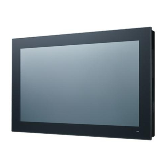
- Page 1 User Manual PPC-3211W Intel® Core i processor based microcomputer, with 21.5" color TFT LCD display...
- Page 2 No part of this manual may be reproduced, copied, translated or transmitted in any form or by any means without the prior written permission of Advantech Co., Ltd. Information provided in this manual is intended to be accurate and reliable. How- ever, Advantech Co., Ltd.
- Page 3 This product has passed the CE test for environmental specifications when shielded cables are used for external wiring. We recommend the use of shielded cables. This kind of cable is available from Advantech. Please contact your local supplier for ordering information.
- Page 4 The sound pressure level at the operator's position according to IEC 704-1:1982 is no more than 70 dB (A). DISCLAIMER: This set of instructions is given according to IEC 704-1. Advantech disclaims all responsibility for the accuracy of any statements contained herein.
- Page 5 Battery Information Batteries, battery packs and accumulators should not be disposed of as unsorted household waste. Please use the public collection system to return, recycle, or treat them in compliance with the local regulations. PPC-3211W User Manual...
- Page 6 PPC-3211W User Manual...
-
Page 7: Table Of Contents
Certification Specifications............3 1.2.6 IP....................3 1.2.7 Power Test Conditions..............3 Dimensions ....................4 Figure 1.1 PPC-3211W dimensions ..........4 Chapter System Installation & Setup ....5 Quick Start Guide..................6 Figure 2.1 Front panel ..............6 Figure 2.2 Side view ..............6 Figure 2.3 Location of I/O interfaces.......... - Page 8 Adjustment of LCD Brightness............ 31 4.2.3 COM3 Mode Selection (RS422/RS485) ........33 4.2.4 BIOS AT & ATX Setup..............35 4.2.5 Wake on LAN or Ring ..............37 4.2.6 Installing RAID ................38 4.2.7 TPM Settings ................43 PPC-3211W User Manual...
-
Page 9: Chapter 1 General Information
Chapter General Information This chapter gives background information on the PPC-3211W panel PC. Sections include: Introduction Specifications Dimensions... -
Page 10: Introduction
Introduction The PPC-3211W is a new generation Panel PC with WXGA (1920 x 1080) screen. The system is equipped with a high performance Intel Core i CPU and with a high efficiency fanless thermal design in which the heat is easily dissipated. It has multiple... -
Page 11: Power Specifications
EMC: CE, FCC Class B, BSMI 1.2.6 Front Panel IP Grade: IP65 1.2.7 Power Test Conditions PPC-3211W's power test conditions are as follows: Test Software Test Configuration Test System Memory: 16G SO-DDR4-2400 x 1 HDD:500G WD AV 2.5”x 1 Burn in 8.1... -
Page 12: Dimensions
Dimensions Figure 1.1 PPC-3211W dimensions Supports VESA 100 x 100mm & 75 x 75mm; please use M4 Note! screws, 6 mm depth (maximum). Use suitable mounting apparatus to avoid risk of injury. PPC-3211W User Manual... -
Page 13: Chapter 2 System Installation & Setup
Chapter System Installation & Setup Sections include: Quick Installation Guide Installation Procedures Installing Memory Installing HDD Installing M.2 Installing Wireless LAN Installing Side COM Port/GPIO Installing TPM Installing Expansion Card AT/ATX Function Switch ... -
Page 14: Quick Start Guide
Figure 2.1 Front panel Power status indicator, off (S5): orange, on (S0): blue Figure 2.2 Side view Quick installation clip (two) Antenna hole (two) Panel Mount Bracket holes (twelve) Side RS-232x2 interface (optional) CPU cooler Speaker (two) PPC-3211W User Manual... - Page 15 A: PCI/PCIE x4 Expansion slot B: Line out/Mic in C: 4 x USB 3.0 D: 2 x Giga Ethernet E: VGA F: DP G: 2xCOM RS232 H: DC power(9-32 V) I: 1 x COM RS422/485 J: Power button K: Grounding screw PPC-3211W User Manual...
-
Page 16: Installation Procedures
Connecting the Keyboard and Mouse Connect the keyboard and mouse to panel PC’s I/O interfaces. 2.2.3 Power ON The power button is located in the right bottom side of the panel PC. Note! Power cable and adapter are optional. PPC-3211W User Manual... -
Page 17: Install Memory Card
(See Fig 2.9), and take out the strength plate & CPU heatsink. Note! Take out the black and blue thermal grease from the accessary box (as indicated in Figure 2.10). Attach the CPU heatsink and strength plate after the grease is applied. Figure 2.10 Figure 2.9 PPC-3211W User Manual... -
Page 18: Installing The Hdd
HDD and then fix the strength-plate (8 screws will be needed if using two HDDs). Lock the HDD bracket, and connect the HDD cable to the mainboard. (See Fig 2.13) Figure 2.11 Figure 2.12 Figure 2.13 PPC-3211W User Manual... -
Page 19: Installing M.2
(See Fig 2.14) Plug the M.2 into the mainboard interface, and remove the 2 M2.5x4 screws from the accessory box to fix it (See Fig 2.15). Return the rear cover and strength-plate. Figure 2.14 Figure 2.15 PPC-3211W User Manual... -
Page 20: Installing Wireless Lan Card
Remove the two plugs on the left and right sides of the rear cover. (See Fig 2.19) Return the rear cover and install the antenna of the wireless LAN card module. (See Fig 2.20) Note! For wireless LAN card module, choose Advantech Product: (Part No. PPC-WLAN-C1E). Figure 2.19 Figure 2.18 PPC-3211W User Manual... - Page 21 Figure 2.20 PPC-3211W User Manual...
-
Page 22: Installing Side Com Port/Gpio
CN13 is located based on the figure below. Then put the rein- forcing plate and the back cover to their original places. If you insert the cable of COM5 into CN12,COM5 will support GPIO. COM4 CN13 CN16 COM5 /GPIO CN12 PPC-3211W User Manual... -
Page 23: Installing Tpm (Current Mechanism Only Supports 98R3P321110)
TPM board. The direction of the line is as follows. Align the white point of the TPM Cable Pin 1 and the Pin of the motherboard CN14, and insert the screws on the reinforcing plate. PPC-3211W User Manual... -
Page 24: Installing The Riser Card
Figure 2.22 Figure 2.23 Figure 2.24 2.10 AT/ATX Function Switch The switch is built in to the machine. Use it to choose AT/ATX functions without removing the rear cover. Figure 2.25 ATX mode Figure 2.26 AT mode PPC-3211W User Manual... -
Page 25: Grounding Installation
Loosen the screws, remove down the plastic cover, plug in the grounding cable, and then fix the screws. (See Fig 2.27 ~ Fig 2.30) Figure 2.27 Figure 2.28 Figure 2.29 Figure 2.30 Note! The grounding cable is not provided in the accessory box. PPC-3211W User Manual... -
Page 26: Hook Installation
Follow the figures below: Hook Put the machine into the carbinet, and prepare the hook. Install the hook into the hole to hold the machine as shown above Screw Secure the machine by fastening the screws Figure 2.31 Hook Installation PPC-3211W User Manual... -
Page 27: Solo Quick Installation
Users can independently complete the panel wallmount installation by quick installa- tion guide. Follow the procedures below: Loosen the two screws at the base, see the figure below. Push the machine into a gap in the wall, the spring hook will lock the machine into the wall. PPC-3211W User Manual... - Page 28 Section 2.10 “Hook Installation”. Note! It is recommend that the mount thickness is smaller than 2 mm (0.079”) according to quick installation guide. For other situations, the recom- mended thickness is less than 6 mm (0.236”). PPC-3211W User Manual...
-
Page 29: Jumper Configuration
Chapter Jumper Configuration Sections include: Jumper & Connectors External COM Port Pin Defini- tion... -
Page 30: Jumper & Connectors
COM Pin9 Power Select (COM1&COM2) CN22 Power Button CN24 Power Input CN29 Front LED CN36 COM3 (RS422/485) AMP1 Amplifier Conn JP1/JP2 Invert Enable/PWM Power Select Panel Power Select Touch Power Select RTC Reset Panel Resolution AT/ATX Select PPC-3211W User Manual... - Page 31 Picture Invert Enable Power Select (1-2) (2-3) 3.3V Default* Picture Invert PWM Power Select (1-2) (2-3) 3.3V Default* Picture Panel Power Select (1-2) (2-3) 3.3V Default* Picture Resistance Touch Power Select (1-2) 3.3VSB Default* (2-3) 3.3V PPC-3211W User Manual...
- Page 32 Picture RTC Reset (1-2) Normal* Default* (2-3) CMOS Clear CN18 Picture COM1/2 RING and Power Select (1-3)/(2-4) P11/P12 COM1/COM2 RI Default* (3-5)/(4-6) P13/P14 COM1/COM2 5V (7-9)/(8-10) P15/P16 COM1/COM2 12V PPC-3211W User Manual...
- Page 33 AT/ATX Select 1,2,3 off; 4 on 1920*1080(48bit) PPC-3211W 1,2 off; 3, 4 on 1920*1080(48bit) PPC-3151W AT/ATX Select ATX Power Default* AT Power PPC-3211W User Manual...
- Page 34 CN12 GPIO Name GPIO4 GPIO0 GPIO5 GPIO1 GPIO6 GPIO2 GPIO7 GPIO3 PPC-3211W User Manual...
-
Page 35: External Com Port Pin Definition
COM 1 and COM 2 (RS232, pin 9 supports 5 V/12 V output) COM 3 RS-422/485 COM 1-2: COM1/COM2 RING or 5V/12V output Pin 9 is set as RI signal in COM port by default, and could be set as 5V/12V output by Jumper PPC-3211W User Manual... - Page 36 (1) 8 data bits + 1 parity bit + 1stop bit (2) 8 data bits + 1 parity bit + 2 stop bits (3) 8 data bits + 2 stop bits PPC-3211W User Manual...
-
Page 37: Software Configuration
Chapter Software Configuration Sections include: Installing Drivers BIOS Setup Program... -
Page 38: Install Divers
Install Divers Before installing software on the panel PC, install the corresponding drivers to ensure full functionality. All drivers can be downloaded from the Advantech website http://www.advantech.com BIOS Setup Program 4.2.1 Entering BIOS Setup When the power is turned on, press the <Del> button to enter BIOS setup screen. -
Page 39: Adjustment Of Lcd Brightness
4.2.2 Adjustment of LCD Brightness Select "System Agent (SA) Configuration" in "Chipset" tab. Then select "Graphics Configuration". PPC-3211W User Manual... - Page 40 Select "LCD Control". There will be six brightness levels to choose in "Brightness Manual Control" PPC-3211W User Manual...
-
Page 41: Com3 Mode Selection (Rs422/Rs485)
4.2.3 COM3 Mode Selection (RS422/RS485) Select "NCT6106D Super IO Configuration" in the "Advanced" tab. Select "Serial Port 3 Configuration" and click to select. PPC-3211W User Manual... - Page 42 Select "Serial Port 3 Mode" and then click to select COM3 operation mode [RS422] or [RS485] When COM3 Mode is selecting RS485, "RS485 Auto Flow" also can select [Enabled] or [Disabled] PPC-3211W User Manual...
-
Page 43: Bios At & Atx Setup
When COM3 Mode is RS422/RS485, "Serial Port3 Terminal" can also select [Enabled] or [Disabled] 4.2.4 BIOS AT & ATX Setup Select "PCH-IO Configuration" in the "Chipset" tab. PPC-3211W User Manual... - Page 44 In "Restore AC Power Loss", set "Power On" for "AT mode" and "Power Off" for "ATX mode". PPC-3211W User Manual...
-
Page 45: Wake On Lan Or Ring
4.2.5 Wake on LAN or Ring Select "PCH-IO Configuration" in the "Chipset" tab. Set "Wake on By PCIE Wake" to "Enabled" if wake up is through I211 or Ring. PPC-3211W User Manual... -
Page 46: Installing Raid
Set "Wake on LAN Enable" to "Enabled" if wake up is through I219. 4.2.6 Installing RAID Press the Del key to enter the BIOS and select "PCH-IO Configuration" under Chipset. PPC-3211W User Manual... - Page 47 Select "SATA AND RST Configuration" and press Enter. Select "SATA Mode Selection" and select "Intel RST Premium with Intel Optane System Acceleration". Save and restart the BIOS Setup interface. PPC-3211W User Manual...
- Page 48 Select "Intel(R) Rapid Storage Technology" under the "Advanced" option. Select "Create RAID Volume" to enter the RAID settings page. PPC-3211W User Manual...
- Page 49 Set "Name" and "RAID Level" and select the corresponding storage device. PPC-3211W User Manual...
- Page 50 Finally select "Create Volume". Save and exit the BIOS setup interface, and allow the machine to boot from the installation device to enter normal installation procedures. PPC-3211W User Manual...
-
Page 51: Tpm Settings
4.2.7 TPM Settings Press the Del key to enter the BIOS and select "Trusted Computing" under Advanced. Change the Security Device Support setting to "Enable", save and exit and restart. PPC-3211W User Manual... - Page 52 Entering the BIOS again will show that the device is found, and then it can oper- ate normally. PPC-3211W User Manual...
- Page 53 PPC-3211W User Manual...
- Page 54 No part of this publication may be reproduced in any form or by any means, electronic, photocopying, recording or otherwise, without prior written permis- sion of the publisher. All brand and product names are trademarks or registered trademarks of their respective companies. © Advantech Co., Ltd. 2019...
Need help?
Do you have a question about the PPC-3211W and is the answer not in the manual?
Questions and answers