Table of Contents
Advertisement
Available languages
Available languages
Quick Links
U0573967-D / 02.02.2021
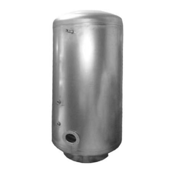
CORFLINOX
Ballon Inox 300 à 900 litres
300 to 900-litre stainless steel tank
Opslagvat in rvs 300 tot 900 liter
Notice d'installation,
d'utilisation et d'entretien
Installation, use and
maintenance instructions
Handleiding:
installatie, gebruik en
onderhoud
SITE DE CAUROIR
Route de Solesmes
FR - 59400 CAUROIR
Advertisement
Table of Contents

Related Manuals for Atlantic CORFLINOX 300


Summary of Contents for Atlantic CORFLINOX 300
- Page 1 U0573967-D / 02.02.2021 CORFLINOX Ballon Inox 300 à 900 litres 300 to 900-litre stainless steel tank Opslagvat in rvs 300 tot 900 liter Notice d'installation, d'utilisation et d'entretien Installation, use and maintenance instructions Handleiding: installatie, gebruik en onderhoud SITE DE CAUROIR Route de Solesmes FR - 59400 CAUROIR...
- Page 3 AVERTISSEMENT ATLANTIC se réserve le droit de modifier les caractéristiques du matériel décrites dans ce manuel à tout moment et sans préavis. WARNING ATLANTIC reserves the right to change the features of equipment described in this manual at any time without prior notice.
-
Page 4: Table Of Contents
SOMMAIRE / CONTENTS / INHOUD 1. Homologations ........................5 2. Descriptif des ballons de stockage ................... 5 3. Mise en place de l'appareil ....................6 4. Raccordement hydraulique ....................7 5. Eléments électriques ......................9 6. Mise en service ......................... 9 7. -
Page 5: 1. Homologations
1. HOMOLOGATIONS - Etiquetage énergétique (2010/30/UE) : à partir du 26/09/2015 En application à la directive et selon les exigences du règlement (UE) n° 812/2013 du 18 février 2013, les informations des réservoirs de stockage dont le volume est inférieur ou égal à... -
Page 6: Mise En Place De L'appareil
Une plaque signalétique contenant les informations concernant le ballon est située sur le bas du ballon dans l'axe du thermomètre et sur la jaquette. Veuillez noter ces indications avant de faire appel au Service Après Vente. 3. MISE EN PLACE DE L'APPAREIL •... -
Page 7: Raccordement Hydraulique
4. RACCORDEMENT HYDRAULIQUE Avant de procéder au raccordement hydraulique, il est indispensable de bien nettoyer les tuyauteries d’alimentation pour ne pas introduire dans la cuve des particules métalliques ou autres. Le DTU Plomberie 60.1 (NFP 40-201) doit être respecté. Dans le cas d’utilisation de tuyauteries métalliques, le raccordement sur la sortie eau chaude devra impérativement être réalisé... - Page 8 Tableau de préconisation des sécurités hydrauliques pour les Ballons de stockage : Modèle ballons stockage Groupe de sécurité G 1" G 1 ¼" (2 x G 1") Important : • Dans le cas d’installation de plusieurs appareils en batterie, il est impératif d’installer un ensemble soupape, vanne sur chaque réservoir et clapet anti-retour sur arrivée générale.
-
Page 9: Eléments Électriques
5. ÉLÉMENTS ÉLECTRIQUES Sur CORFLINOX option Blindé Il est possible de rajouter des résistances blindées de 3 à 6 kW selon les associations recommandées suivantes : Résistance blindée Association recommandées 3 kW tri 230 / 400 V 300 à 900 L 6 kW tri 400 V 300 à... -
Page 10: Garantie
En cas de défaut de fabrication ou vice de matière (il appartient toujours à l’acheteur d’en faire la preuve) nettement établi et reconnu par le Groupe Atlantic, la responsabilité du Constructeur est limité à : •... -
Page 11: Fin De Cycle De Vie
• Détériorations provoquées par le gel, la foudre, un dégât des eaux, un tirage défectueux, une mauvaise ventilation du local, et en général, toute cause reconnue à son caractère exceptionnel. Une installation non conforme à la réglementation, aux normes et aux règles de l’Art : •... -
Page 12: Pièces Détachées
10. PIÈCES DÉTACHÉES Liste des pièces devant être remplacé régulièrement ou systématiquement lors d'une intervention : Référence Joint de bride latérale seul 551564 Joint de bride supérieure seul 551566 Capot d'isolation bride SM1 552945 Plaque de fermeture bride latérale 551565 Plaque de fermeture bride supérieure 551567 Doigt de gant (unité) -
Page 13: 1. Certification
1. CERTIFICATION - Energy labelling (2010/30/EU): from 26/09/2015 In application of the directive and according to the requirements of the EU regulation No. 812/2013 of 18 February 2013, the information on storage tanks with a volume of less than or equal to 500 litres is available in appendix B (see page 31). - Eco-design (2009/125/EC): from 26/09/2015 In application of the directive and according to the requirements of EU regulation no. -
Page 14: Installing The Equipment
An identification plate containing information about the tank is attached to the base of the tank in line with the thermometer and on the jacket. Please take note of these details before contacting After-Sales Service. 3. INSTALLING THE EQUIPMENT • Place the tank and its safety unit (and/or safety valve) in a frost-free place. •... -
Page 15: Hydraulic Connection
4. HYDRAULIC CONNECTION Before proceeding with the hydraulic connection, the supply pipes must be thoroughly cleaned to avoid introducing metal or other particles into the tank. If metal pipes are used, the connection to the hot water outlet must use a dielectric pipe joint or cast-iron sleeve to prevent galvanic corrosion (iron-copper). -
Page 16: Electric Elements
Important: • If an array of several devices is installed, a valve assembly must be fitted to each tank and a non-return flap on the overall supply pipe. • If the pressure of the distribution network exceeds 5 bar, a pressure reducer must be fitted to the overall supply pipe. -
Page 17: Commissioning
6. COMMISSIONING • Fill the device - Open a hot water tank in the distribution system, - Open the cold water tap on the safety unit, ensuring that the unit's drainage valve is closed, - After drawing from the hot water taps with no noise in the pipes, close the taps: your equipment is full. -
Page 18: Warranty
In the event of a clearly established manufacturing fault or defective materials (which must be proved by the purchaser) acknowledged by Groupe Atlantic, the manufacturer's liability is limited to: • Removable boiler parts: supplying a replacement for the part acknowledged to be faulty... -
Page 19: End Of Life
9. END OF LIFE The apparatus must be dismantled and recycled by a specialist service provider. The apparatus must never be disposed of with household waste, large objects or in landfill. When the apparatus reaches the end of its life, please contact your installer or the local representative in order to proceed with the dismantling and recycling of the apparatus. -
Page 20: 1. Goedkeuringen
1. GOEDKEURINGEN - Energie-etikettering (2010/30/EU): vanaf 26/09/2015 Op grond van de richtlijn en de eisen van het reglement (EU) nr 812/2013 van 18 februari 2013, moet de informatie over de opslagreservoirs met een volume minder dan of gelijk aan 500 liter beschikbaar zijn in bijlage B (zie pagina 31). - Eco-ontwerp (2009/125/EG): vanaf 26/09/2015 Op grond van de richtlijn en de eisen van het reglement (EU) nr 814/2013 van 02 augustus 2013, moet de informatie over de opslagreservoirs met een volume minder dan of van... -
Page 21: Plaatsen Van Het Apparaat
3. PLAATSEN VAN HET APPARAAT • Bescherm de boiler en de veiligheidsgroep (en / of de veiligheidsklep) tegen de vorst. • Plaats deze zo dicht mogelijk bij de belangrijkste afvoerpunten. • Indien deze geplaatst is buiten de leefruimte, isoleer dan de leidingen. Als dit moet worden geïnstalleerd in een ruimte waar de omgevingstemperatuur constant boven de 35ºC is, zorgen voor ventilatie van de ruimte. - Page 22 Aanbevelingen: Voor gebieden waar het water erg hard is (Th>20ºF), zal het gebruik van een waterontharder niet leiden tot het vervallen van onze garantie op voorwaarde dat de waterontharder is ingesteld volgens de regels van de kunst, en regelmatig wordt gecontroleerd en onderhouden.
-
Page 23: Elektrische Elementen
4.3.2. Veiligheidskleppen: Veiligheidskleppen zijn geïnstalleerd op de ingang van de tank via een T-stuk (zie schema's hieronder). VEILIGHEIDSGROEP VEILIGHEIDSKLEP Enkel op koudwaterinlaat Op ingang tank Kit 1" ¼ van 2 groepen G 1 enkele groep G 1" 1" Klepdiameter ≥ diameter aansluiting boiler Ventiel / terugslagklep / klep Nooit een afsluiter of terugslagklep monteren tussen de veiligheidsklep of... -
Page 24: Ingebruikname
6. INGEBRUIKNAME • Vul het apparaat - Open een warmwaterkraan op de distributie, - Open de koudwaterkraan op de veiligheidseenheid, en ervoor zorgen dat de aflaatklep van de groep in de gesloten positie blijft, - Na het uitstromen van water uit de warmwaterkranen zonder lawaai in de leidingen, sluit deze: het apparaat is vol. -
Page 25: Garantie
In het geval van fabricagefouten of gebrekkig materiaal (altijd door de koper te bewijzen), duidelijk vastgesteld en erkend door de Atlantic Group, is de aansprakelijkheid van de fabrikant beperkt tot: • Verwijderbare onderdelen van de ketel: bij de levering van erkende defecte onderdeel... -
Page 26: Einde Levenscyclus
9. EINDE LEVENSCYCLUS De ontmanteling en recycling van de apparaten moet worden uitgevoerd door een gespecialiseerde dienst. In geen geval mag het apparaat worden afgevoerd met het volumineuze huishoudelijk afval of naar een stortplaats. Neem bij het einde van de levensduur van het apparaat contact op met uw installateur of de lokale vertegenwoordiger voor de ontmanteling en recycling van dit apparaat. -
Page 27: Annexe A - Caractéristiques Techniques
ANNEXE A APPENDIX A BIJLAGE A 02.02.2021 CORFLINOX 27 / 32... - Page 28 CARACTÉRISTIQUES TECHNIQUES 300 L 500 L 750 L 900 L Capacité utile (L) Poids à vide (kg) Cote de basculement (mm) 1765 1800 1830 2001 Ø DN 1038 1045 1136 1285 1315 1293 1468 1535 1515 1518 1693 1710 1737 1763 1938 HT avec isolation...
- Page 29 TECHNICAL SPECIFICATIONS 300 L 500 L 750 L 900 L Useful capacity (L) Tank weight (kg) Height when tilted (mm) 1765 1800 1830 2001 Ø DN 1038 1045 1136 1285 1315 1293 1468 1535 1515 1518 1693 1710 1737 1763 1938 HT with insulation 1810...
- Page 30 TECHNISCHE EIGENSCHAPPEN 300 L 500 L 750 L 900 L Nuttige capaciteit (L) Gewicht kuip (kg) Kantelkant (mm) 1765 1800 1830 2001 Ø DN 1038 1045 1136 1285 1315 1293 1468 1535 1515 1518 1693 1710 1737 1763 1938 HT met isolatie 1810 1837 1863...
-
Page 31: Annexe B - Données Des Produits ≤ 500 L Et ≤ 2000 L
Statische verliezen Energie- Opslagvolume efficiëntieklasse Handelsmerk Classe / Class / Nom / Name / Naam Code S (W) V (L) Klasse Corflinox 300-SM1 545 900 77,50 Corflinox 300-TM0 545 904 72,92 Atlantic Corflinox 500-SM1 545 901 99,58 Corflinox 500-TM0 545 905... - Page 32 SATC ATLANTIC SOLUTIONS CHAUFFERIE THERMOR SERVICES 1 route de Fleurville 17 rue Croix Fauchet - BP 46 01190 PONT DE VAUX 45141 SAINT-JEAN-DE-LA-RUELLE Tél. : 03 51 42 70 03 Tel.: Fax : 03 85 51 59 30 www.thermor.fr www.atlantic-solutions-chaufferie.fr...
Need help?
Do you have a question about the CORFLINOX 300 and is the answer not in the manual?
Questions and answers