Table of Contents
Advertisement
Available languages
Available languages
Quick Links
CALYPSO
SPLIT INVERTER
CHAUFFE-EAU THERMODYNAMIQUE
HEAT PUMP WATER HEATER - WARMTEPOMP
BALLON 150L ET 200L
Tank - Vat
FR
EN
NL
TRINEO
NOTICE D'INSTALLATION
ET D'UTILISATION
Installation and operating manual
Installatie- en gebruiksvoorschriften
À CONSERVER PAR L'UTILISATEUR
Manual must be kept by end user
Richtlijnen te bewaren door de gebruiker
Tous les outils
pour piloter votre
CALYPSO SPLIT INVERTER
Tous les outils
pour piloter votre
TRINÉO
Advertisement
Chapters
Table of Contents

Related Manuals for Atlantic CALYPSO


Summary of Contents for Atlantic CALYPSO
- Page 1 SPLIT INVERTER CHAUFFE-EAU THERMODYNAMIQUE HEAT PUMP WATER HEATER - WARMTEPOMP BALLON 150L ET 200L Tank - Vat Tous les outils pour piloter votre CALYPSO SPLIT INVERTER Tous les outils pour piloter votre TRINÉO NOTICE D’INSTALLATION ET D’UTILISATION Installation and operating manual Installatie- en gebruiksvoorschriften À...
- Page 2 Comment bien INSTALLER le ballon de mon chauffe-eau thermodynamique Calypso Split Inverter ou de ma solution 3 services Trinéo ATTENTION : Effectuer le remplissage du ballon avant la mise sous tension. ÉTAPE 1 I MISE EN PLACE a - Chauffe-eau mural 150L et 200L : Il peut être fixé...
- Page 3 ÉTAPE 4 I MISE EN SERVICE OBLIGATOIRE POUR CHOISIR LE SYSTÈME CALYPSO SPLIT INVERTER OU TRINEO Mettre l’appareil sous tension et suivre les indications affichées sur l’écran. Il vous sera demandé de choisir le système dans lequel le chauffe-eau doit fonctionner : soit Calypso split inverter, soit Trineo.
- Page 4 SCHÉMA ÉLECTRIQUE TRINEO POUR LA MISE EN SERVICE DE VOTRE Afin d’assurer la protection contre la corrosion de la cuve, le chauffe-eau doit être alimenté en permanence. 1 2 3 L N T 11 12...
-
Page 5: Table Of Contents
Avertissements Avertissements Installation Installation Utilisation Utilisation TABLE DES MATIERES AVERTISSEMENTS ..................3 Précautions d'emploi ................7 Présentation ..................10 2.1. Consignes de sécurité ...................10 2.2. Contenu de l’emballage ..................10 2.3. Manutention ......................10 Dimensions ................... 11 Accessoires ..................12 Installation ....................13 5.1. Choix du lieu d’installation ..................13 5.2. - Page 6 Avertissements Installation Utilisation 11.4. Diagnostic et vérification du bon fonctionnement ..........30 11.5. Mode secours ......................31 11.6. Logiciel ........................31 11.7. Réinitialiser ......................31 12. Entretien du chauffe-eau ..............32 12.1. Entretien par l’utilisateur ..................32 12.2. Entretien par le professionnel ................33 13. Diagnostic de panne ................35 13.1. Affichage des codes erreurs ..................35 13.2. Autres pannes sans affichage de codes erreurs ............39 14. Valeurs ohmiques des sondes en fonction des températures ....42 15.
-
Page 7: Avertissements
Avertissements Installation Utilisation AVERTISSEMENTS Cet appareil n’est pas prévu pour être utilisé par des per- sonnes (y compris les enfants) dont les capacités physiques, sensorielles ou mentales sont réduites, ou des personnes dénuées d’expérience ou de connaissance, sauf si elles ont pu bénéficier, par l’intermédiaire d’une personne responsable de leur sécurité, d’une surveillance ou d’instructions préa- lables concernant l’utilisation de l’appareil. - Page 8 Avertissements Installation Utilisation 1/ Installer l’appareil dans un local à l’abri du gel. La destruc- tion de l’appareil par surpression due au blocage de l’organe de sécurité est hors garantie. 2/ S’assurer que la cloison est capable de supporter le poids de l’appareil rempli d’eau.
-
Page 9: Raccordement Hydraulique
Avertissements Installation Utilisation • Ce produit est destiné pour être utilisé à une altitude maxi- male de 2 000 m. • Ce chauffe-eau est vendu avec un thermostat ayant une température de fonctionnement supérieure à 60°C en posi- tion maximale capable de limiter la prolifération des bacté- ries de Légionelle dans le réservoir. -
Page 10: Raccordement Electrique
Avertissements Installation Utilisation RACCORDEMENT ELECTRIQUE : • Avant tout démontage du capot, s’assurer que l’alimen- tation est coupée pour éviter tout risque de blessure ou d’électrocution. • L’installation électrique doit comporter en amont de l’ap- pareil un dispositif de coupure omnipolaire (disjoncteur, fusible) conformément aux règles d’installation locales en vigueur (disjoncteur différentiel 30mA). -
Page 11: Précautions D'emploi
Avertissements Avertissements Installation Installation Utilisation Utilisation Précautions d'emploi Les travaux d'installation et de service sur les chauffe-eau thermodynamiques peuvent présenter des dangers en raison de hautes pressions et de pièces sous tension électrique. Les chauffe-eau thermodynamiques doivent être installés, mis en service et entretenus par un personnel formé et qualifié uniquement. Conserver les liaisons frigorifiques hermétiquement closes (pincées, repliées, et de pré- férences brasées). L’humidité nuit fortement au bon fonctionnement et à la durée de vie du produit. En cas de pollution, il devient difficile et parfois impossible de dépolluer le circuit. -
Page 12: Raccordement Électrique
Avertissements Installation Utilisation • Ne pas libérer le réfrigérant dans l’atmosphère. En cas de fuite de réfrigérant, pen- dant l’installation, aérer la pièce. A la fin de l’installation, aucune fuite de réfrigérant ne doit être présente sur le circuit. Une fuite de fluide R32 couplée à une source d’inflammation peuvent dégager des gaz toxiques. • Ne pas toucher le fluide frigorigène lors de fuite des liaisons ou autre. Un contact direct peut provoquer des gelures. - Page 13 Avertissements Avertissements Installation Installation Utilisation Utilisation • Veiller à placer le disjoncteur à un endroit où les utilisateurs ne peuvent pas le démar- rer ou l’arrêter involontairement (local annexe, ...). Lorsque le tableau électrique se trouve en extérieur, le refermer et le verrouiller afin qu’il ne puisse pas être facilement accessible. • Ne jamais toucher les composants électriques immédiatement après que l’alimenta- tion ait été...
-
Page 14: Présentation
Avertissements Installation Utilisation Présentation 2.1. Consignes de sécurité Les travaux d’installation et de mise en service sur les chauffe-eau thermodynamiques peuvent présenter des dangers en raison de hautes pressions et de pièces sous tension électrique. Les chauffe-eau thermodynamiques doivent être installés, mis en service et entretenus par un personnel formé et qualifié uniquement. 2.2. Contenu de l’emballage 1 notice 1 sachet contenant le raccord diélec- trique et 2 joints pour la sortie eau chaude 2 manchons d’isolation pour le rac- cordement frigorifique... -
Page 15: Dimensions
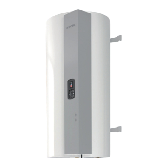
Avertissements Installation Utilisation Dimensions Piquage eau chaude 3/4" 150 l 200 l Piquage eau froide 3/4" Cote A 1177 1497 Boîtier raccordement électrique Ecran de régulation Emplacement appoint électrique & sécurité mécanique ; ... -
Page 16: Accessoires
Avertissements Installation Utilisation Accessoires Trépied pour chauffe-eau vertical mural 12 12... -
Page 17: Installation
Avertissements Installation Utilisation Installation 5.1. Choix du lieu d’installation • Placer le chauffe-eau à l’abri du gel. • Le positionner le plus près possible des points d’utilisation importants. • S’il est placé en dehors du volume habitable (cellier, garage), calorifuger les tuyau- teries. La température ambiante autour du chauffe-eau ne doit pas dépasser 40 °C. • S’assurer que l’élément support est suffisant pour recevoir le poids du chauffe-eau plein d’eau. •... -
Page 18: Grilles : Contraintes Concernant Le Nombre, La Taille Et La Position
Avertissements Installation Utilisation Cas du local avec ventilation mécanique : Dans ce cas, il n’existe pas de contrainte en terme de surface minimale, à condition que la ventilation respecte les critères ci-dessous : • Débit de ventilation supérieur à 60m3/h. •... -
Page 19: Emplacement
Avertissements Installation Utilisation Taille des ouvertures : leur taille minimale Smin en cm² dépend de la charge en R32 et de la surface de la pièce dans laquelle est installé le produit. Voir tableau ci-dessous. Surface de la pièce dans laquelle Placard est installé... -
Page 20: Mise En Place Du Produit
Avertissements Installation Utilisation 5.5. Mise en place du produit Installer impérativement un bac de récupération d'eau raccordé à l'égout, sous le chauffe-eau, en particulier lorsque celui-ci est positionné au-dessus de locaux habités. • Mettre en place et serrer easyFIX • Installer le chauffe-eau Installation en placard non ventilé... -
Page 21: Raccordement Hydraulique
Avertissements Installation Utilisation Poser chauffe-eau d’abord sur son trépied pour marquer les points de fixation. Réaliser les perçages. Installer le chauffe-eau à sa place. Le fixer au mur. Fixer l’étrier supérieur 5.6. Raccordement hydraulique Avant de procéder au raccordement hydraulique, il est absolument indispensable de bien nettoyer les tuyauteries d’alimentation afin de ne pas risquer d’introduire dans la cuve du chauffe-eau des particules métalliques ou autres. - Page 22 Avertissements Installation Utilisation • L ’étanchéité doit être effectuée à l’installation sur les tubulures, y compris dans le cas d’utilisation de tuyaux PER. • Installer obligatoirement un groupe de sécurité neuf (non fourni) directement sur l’en- trée d’eau froide du chauffe-eau, qui respectera les normes en vigueur (en Europe : EN 1487), de pression 0,7 MPa – 7 bar – et de dimension ¾″ (20/27). Raccorder le groupe de sécurité...
-
Page 23: Raccordement Frigorifique
Avertissements Installation Utilisation 5.6.3. Conseils et recommandations Si les points de puisage ne sont pas équipés de mitigeurs thermostatiques, un limiteur de température doit être installé en sortie de chauffe-eau pour limiter les risques de brûlures : • Dans les pièces destinées à la toilette, la température maximale de l’eau chaude sanitaire est fixée à 50 °C aux points de puisage. • Dans les autres pièces, la température de l’eau chaude sanitaire est limitée à 60 °C aux points de puisage. - Page 24 Avertissements Installation Utilisation En cas d’abonnement heures creuses / heures pleines, la régulation optimisera le temps de chauffe en fonction des heures creuses. Pour cela, il est alors nécessaire que la régu- lation reçoive l’information heures creuses / heures pleines du tableau électrique (par simple présence ou non de 230V). En cas de remplacement de chauffe-eau branché directement sur le contact heures creuses / heures pleines, l’ancienne alimentation peut être utilisée à cet effet (si elle est en 20 ampères et câblée en 3G2.5 mm²) après adaptation en alimentation continue.
-
Page 25: Première Mise En Service
+ seulement" Chauffage/Froid" CALYPSO SPLIT INVERTER TRINEO Pour Calypso Split Inverter, suivre Pour Trineo, se référer cette notice à la notice de l'unité intérieure pour la mise en service pour la mise en service. 21 21... -
Page 26: Installation Partielle
Si l'installation du système n'est pas complète, c'est-à-dire sans le raccordement de l'unité extérieure pour le système Calypso Split Inverter, ou sans le raccordement de l'unité inté- rieure pour le système Trineo, il est possible de faire fonctionner le ballon avec l'appoint électrique uniquement. -
Page 27: Paramètres D'installation
Avertissements Installation Utilisation 6.2. Paramètres d’installation (si non effectués à la première mise en service) Pour accéder à nouveau aux différents réglages de l’installation : Menu Paramètres 6.2.1. Pilotage externe Le chauffe-eau peut être raccordé à un signal Heure Creuse ou un signal autoconso pho- tovoltaïque, ou un signal Smart Grid. • Signal Heure Creuse : Dans ce mode, l'appoint électrique ne peut fonctionner que lorsque le signal est présent. Trois choix sont possibles pour le fonctionnement de la pompe à... - Page 28 Avertissements Installation Utilisation Sans signal photovoltaïque, le système est autorisé à fonctionner selon les 2 paramé- trages suivants : • soit la journée, uniquement, de 10 h à 17 h • soit la journée et en complément la nuit, si besoin •...
- Page 29 Avertissements Installation Utilisation 6.2.2. Plages de chauffe Ce paramètre définit les plages d’autorisation de démarrage de la pompe à chaleur et de l’appoint électrique en fonction du besoin en eau chaude. Il est paramétrable dans le cas où il n'y a pas de raccordement au signal heure creuse, ou au signal autoconso photovoltaïque.
-
Page 30: Le Panneau De Commandes
Avertissements Installation Utilisation Le panneau de commandes Lun 17:20 Signal wifi pour Calypso Consigne Split Inverter Voyant : - En rouge : quantité d’eau chaude dispo- nible - En mouvement : chauffe en cours Accès rapide aux modes boost et... -
Page 31: Le Menu
Avertissements Installation Utilisation Le menu Pour le système Trineo, se référer à la notice de l'unité intérieure. 9.1. Consommations Ce menu permet de visualiser : • la consommation énergétique en kwh pour la production d’eau chaude, pour le mois en cours, le mois précédent, l’année en cours, l’année précédente, depuis la mise en service ;... -
Page 32: Paramètres
Avertissements Installation Utilisation 9.5. Paramètres 9.5.1. Langue Ce menu permet de choisir la langue d'affichage 9.5.2. Date / Heure Ce menu permet de corriger l'heure : en cas de coupure de courant supérieure à 5 minutes, il peut être nécessaire de remettre à jour la date et l'heure. 9.5.3. -
Page 33: Les Modes De Fonctionnement
Avertissements Installation Utilisation Les modes de fonctionnement 2 modes de fonctionnement sont proposés, via le menu «Gestion consigne» : Menu Gestion Consigne ECO+ Gestion Consigne MANUEL 10.1. Mode ECO+ Le chauffe-eau est autonome et procède à l’apprentissage des consommations pour s’adapter aux besoins de l’utilisateur et faire des économies d’énergie, tout en garantis- sant le confort. -
Page 34: Accès Au Menu Expert Et Au Mode Secours
Avertissements Installation Utilisation Accès au menu Expert et au mode Secours Pour le système Trineo, se référerer à la notice de l’unité intérieure. Pour accéder au menu Expert : Menu Paramètres Accès Expert 11.1. Appoint électrique Voir chapitre «9.5.4. Appoint électrique», page 28. 11.2. -
Page 35: Mode Secours
Avertissements Installation Utilisation Dans le cas contraire, il faut mettre la PAC (mode froid) pour valider son bon fonctionnement. Si les dates et heures ne sont pas renseignées (suite à une coupure de courant par exemple), les erreurs ne seronts pas enregistrées dans l’historique. 11.5. -
Page 36: Entretien Du Chauffe-Eau
Avertissements Installation Utilisation Entretien du chauffe-eau Une vidange du chauffe-eau est nécessaire dans le cas où le mode absence ne peut pas être utilisé ou dès lors que l’appareil est mis hors tension. Procéder de la façon suivante : Couper l’alimentation électrique. Fermer l’arrivée d’eau froide au groupe de sécurité. Ouvrir un robinet d’eau chaude. Ouvrir la vanne de vidange du groupe de sécurité. -
Page 37: Entretien Par Le Professionnel
Avertissements Installation Utilisation 12.2. Entretien par le professionnel Le chauffe-eau doit être mis hors tension avant ouverture. Le remplacement du thermoplongeur ou l’ouverture du chauffe-eau implique la vidange du chauffe-eau et le remplacement du joint. 12.2.1. Accès aux éléments du chauffe-eau Retrait de la colonne supérieure : ... - Page 38 Avertissements Installation Utilisation Pour retirer la commande Tenir le capot de façade et déboîter le haut de la commande en appuyant sur les 2 clips situés à l’arrière Appuyer sur les 2 clips situés plus bas Retirer la commande ...
-
Page 39: Diagnostic De Panne
Avertissements Installation Utilisation Diagnostic de panne En cas d’anomalie, absence de chauffe ou dégagement de vapeur au soutirage, couper l’alimentation électrique et prévenir l’installateur. 13.1. Affichage des codes erreurs Les opérations de dépannage doivent être réalisées exclusivement par un professionnel. Le bip de l’alarme peut être suspendu en appuyant sur OK. Lorsque le défaut est corrigé, le message d’erreur réapparaît pour un dernier acquittement. - Page 40 Avertissements Installation Utilisation Code Diagnostic et Cause Conséquences affiché dépannage Alimentation élec- Vérifier l’alimentation électrique trique discontinue W.19 Sonde de conden- Arrêt de la PAC. Vérifier les connexions et le bon sation défectueuse Chauffe par l’appoint positionnement de la sonde. P.20 (température < 0 °C électrique. Vérifier la valeur ohmique de la sonde. ou > 100 °C) Si RAS, remplacer la sonde.
- Page 41 Avertissements Installation Utilisation Code Diagnostic et Cause Conséquences affiché dépannage Absence d’échange Arrêt de la PAC. Surconsommation ou boucle de thermique Chauffe par l’appoint recyclage ou fuite sur le réseau P.30.1 électrique. d’eau chaude. Pompe à cha- Manque charge : Vérifier la leur fonctionne charge par pesée. en continu sans Incondensables : changer par atteindre la consigne...
- Page 42 Avertissements Installation Utilisation Code Diagnostic et Cause Conséquences affiché dépannage Défaut basse Arrêt de la PAC. Vérifier la charge. pression Chauffe par l’appoint Vérifier que l’unité intérieure est P.52.6 électrique. bien raccordée sur les vannes «AIR» et le ballon sur les vannes «WATER». Défaut général de Arrêt de la PAC. Manque de compatibilité...
-
Page 43: Autres Pannes Sans Affichage De Codes Erreurs
Avertissements Installation Utilisation Défaut de communica- Utilisation récurrente Vérifier que le hub est bien alimenté. tion radio détecté entre de l’appoint électrique Essayer de rapprocher le hub et le le hub et le ballon du ballon pour chauf- ballon fer l’eau. Risque de manque d’eau chaude et/ou chauffage insuffisant 13.2. - Page 44 Avertissements Installation Utilisation Panne constatée Cause possible Diagnostic et dépannage Peu de débit au • Filtre du groupe de sécu- • Nettoyer le filtre. robinet d’eau rité encrassé. chaude. • Chauffe-eau entartré • Détartrer le chauffe-eau. Perte d’eau en • Soupape sécu- • Remplacer le groupe de continu au groupe rité...
- Page 45 Avertissements Installation Utilisation Panne constatée Cause possible Diagnostic et dépannage La pompe à chaleur • Température d’air • Attendre un retour des tem- fonctionne peu de dehors plages pératures à un niveau situé temps, l’appoint tolérées dans les plages tolérées électrique est en •...
-
Page 46: Valeurs Ohmiques Des Sondes En Fonction Des Températures
Avertissements Installation Utilisation Valeurs ohmiques des sondes en fonction des températures Sonde de refoulement Unité extérieure/Sonde de condensation ° C K ohm ° C K ohm ° C K ohm Sonde d’évaporateur Unité extérieure ° C K ohm ° C K ohm °... -
Page 47: Service Après-Vente
Avertissements Installation Utilisation Service après-vente Pour toute commande auprès d’un distributeur de la marque, préciser le type exact de l’appareil et son numéro de série relevés sur la plaque signalétique. L'adresse du service après-vente est rappelée au dos de cette notice. Utiliser uniquement des pièces détachées d’origine constructeur. -
Page 48: Caractéristiques Techniques
0,6 / 6 0,6 / 6 Pression d’eau assignée MPa / Unité extérieure modèle modèle compatible Calypso Split Inverter Trineo H 535 x l 735 x P H 542 x l 867 x P Dimensions Raccordement liaison frigorifique ‘’ 3/8 & 1/4, type Flare 3/8 &... - Page 49 Avertissements Installation Utilisation Unité intérieure modèle modèle modèle Trineo 7 Trineo 9 Trineo 12 Débit d’air (U.int.) PV/GV en m3/h 320/650 320/700 320/700 froid Débit d’air max (u.ext) GV m3/h 1590 1590 1760 en froid Performances climatisation chauffage : EER / SEER average climate 5.00 / 7.40 4.42 / 7.40 3.80 / 7.30...
- Page 50 Avertissements Installation Utilisation Système assemblé modèle Calypso Split modèle compatible Inverter Trineo 230 V monophasé 230 V monophasé Raccordement électrique (tension / fréquence) 50 Hz 50 Hz Puissance maxi totale absorbée par 3250 3630 l’appareil 1450 1830 Puissance absorbée par la PAC Puissance absorbée par l’appoint...
- Page 51 Avertissements Installation Utilisation 202,2 268,9 199,1 267,6 Quantité max. d’eau mélangée à 40° C (V40)* 234,7 303,3 231,88 303,0 V40td (8 h HC) Efficacité énergétique (nwh)* * Performances mesurées en mode sortie usine manuel ECO de 10°C à 55°C pour le 150L et de 10°C à...
-
Page 52: Déclaration De Conformité
2005 + A13 : 2012 EN 62233 : 2008 Déclare que le produit est conforme aux exigences essentielles de la directive RED 2014/53/UE, selon la désignation ci-dessous : Pour le Calypso Split Inverter : Désignation : HM009 SF HWNM01 DHW Type : EMETTEUR-RECEPTEUR RADIO WIFI 2400 A 2483,5 MHz Puissance max de l’antenne :... -
Page 53: Garantie
Avertissements Installation Utilisation Garantie 18.1. Champ d’application de la garantie Sont exclues de cette garantie les défaillances dues à : Des conditions d’environnement anormales : • Dégâts divers provoqués par des chocs ou des chutes au cours des manipulations après départ usine. •... -
Page 54: Conditions De Garantie
Avertissements Installation Utilisation 18.2. Conditions de garantie Le chauffe-eau doit être installé par une personne habilitée conformément aux règles de l’art, aux normes en vigueur et aux prescriptions de nos services techniques. Il sera utilisé normalement et régulièrement entretenu par un personnel formé et qualifié uniquement. Dans ces conditions, notre garantie s’exerce par échange ou fourniture gratuite à notre Distributeur ou Installateur des pièces reconnues défectueuses par nos services, ou le cas échéant de l’appareil, à... - Page 55 Warnings Installation TABLE OF CONTENTS WARNINGS ....................53 Precautions for use ................57 Presentation ..................60 2.1. Safety instructions....................60 2.2. Package contents ....................60 2.3. Handling .........................60 Dimensions ...................61 Accessories ..................62 Installation ....................63 5.1. Selecting the installation site..................63 5.2. Minimum room surface area ..................63 5.3. Grilles: restrictions on the number, size and position..........64 5.4.
- Page 56 Warnings Installation 11.4. Diagnostics and checking operation ..............80 11.5. Emergency mode ....................81 11.6. Software .........................81 11.7. Reset ........................81 12. Servicing the water heater ..............82 12.1. User servicing ......................82 12.2. Professional servicing ....................83 13. Troubleshooting ..................85 13.1. Error code display ....................85 13.2.
-
Page 57: Warnings
Warnings Installation WARNINGS This appliance is not intended for use by persons (including children) with reduced physical, sensory or mental capacities, or by persons lacking experience or knowledge, unless they have received adequate supervision or preliminary instruc- tions on how to use the appliance from a person in charge of their safety. - Page 58 Warnings Installation 3/ If the appliance is to be installed in a room or location where the ambient temperature is constantly higher than 35°C, ensure sufficient ventilation. 4/ For bathrooms, do not install the appli- ance in areas V0, V1 or V2. If there is area 1 not enough space, they can be installed area 0...
-
Page 59: Hydraulic Connection
Warnings Installation HYDRAULIC CONNECTION: A new safety device which conforms to local standards in force, pressure 0.7 MPa (7 bar) and size XX ¾’’ in diameter must be installed on the water heater's inlet. This device must be protected from frost. The pressure relief valve drainage device must be activated on a regular basis in order to remove limescale deposits and to check that it is not blocked. - Page 60 Warnings Installation • If the power cable is damaged, it must be replaced by the manufacturer, its After-Sales service or a similarly qualified professional to prevent any hazards. • Earthing is mandatory. A special terminal marked provided for this purpose. • Refer to the wiring diagrams in the manual. • The user manual for this appliance can be obtained from the After-Sales service •...
-
Page 61: Precautions For Use
Warnings Installation Precautions for use The installation and service work on the thermodynamic water heaters may present haz- ards because of the high pressures and live parts. Thermodynamic water heaters must be installed, commissioned and maintained by trained and qualified professionals only. Keep the refrigeration lines hermetically sealed (clamped, folded and preferably brazed). Moisture is highly damaging to the operation and service life of the product. In case of con- tamination, it becomes difficult and sometimes impossible to decontaminate the circuit. - Page 62 Warnings Installation • Do not touch the refrigerant fluid if there are leaks on the lines or other parts. Direct contact can cause frostbite. • Refrigerant fluids may be odourless. • Comply with the safety and operating rules for R32 fluid. • Comply with the national gas regulations. • Do not puncture or burn the appliance. • An expander installed inside the building must not be reused. The flared union on the pipework must be removed and a new flared union made. • An expander installed outside the building can be reused without any restrictions. •...
- Page 63 Warnings Installation • Incorrect wiring can damage the system as a whole. • If the voltage is too low or drops during start-up, the appliance may have difficulty starting. In this case, please contact your energy provider. • Make sure that all cables are secure, that the wiring complies with the current stand- ards (NF C 15-100 in particular), and that no force is being exerted on the terminal connections or cables.
-
Page 64: Presentation
Warnings Installation Presentation 2.1. Safety instructions Installation and set-up work on thermodynamic water heaters may present hazards due to high pressures and live parts. Thermodynamic water heaters must be installed, commissioned and maintained by trained and qualified professionals only. 2.2. Package contents 1 manual 1 pouch with dielectric union and 2 seals for the hot water outlet 2 insulation sleeves for connecting the refrigeration lines 2 easyFIX mountings... -
Page 65: Dimensions
Warnings Installation Dimensions 3/4" hot water branch connection 150 l 200 l 3/4" cold water branch connection Dimen- 1177 1497 Switch box electrical connection sion A Control system screen ... -
Page 66: Accessories
Warnings Installation Accessories Tripod for vertical wall-mounted water heater 62 62... -
Page 67: Installation
Warnings Installation Installation 5.1. Selecting the installation site • Install the water heater in a frost-free location. • Position it as close as possible to the main loads. • Insulate its pipework if the appliance is installed outside in uninhabitable areas (stor- age rooms, garages). -
Page 68: Grilles: Restrictions On The Number, Size And Position
Warnings Installation Room with mechanical ventilation: In this case, there are no restrictions relating to minimum surface area, provided that the ventilation meets the criteria below: • Ventilation flow rate greater than 60 m3/h. • The lowest point on the extraction outlet is at least 100 mm from the ground. •... -
Page 69: Location
Warnings Installation Size of openings: their minimum size Smin in cm² depends on the R32 charge and the surface area of the room in which the product is installed. See table below. Surface area of the room in Cabinet which the product is installed in 0.36~0.42 m² Minimum surface area (Smin) of the lower ventilation grille in cm² 5.4. -
Page 70: Mounting The Product
Warnings Installation 5.5. Mounting the product A drain pan connected to the sewer system must be installed under the water heater, particularly when it is positioned above inhabited rooms. • Mount and tighten the easyFIX • Install the water heater Installation in an unventilated cabinet prohibited A tripod must be used with a non-load bearing wall (unable to bear the weight of the tank when filled). In this case, the water heater must be wall-mounted using the upper bracket. -
Page 71: Hydraulic Connection
Warnings Installation First put the water heater on its tripod to mark the fastening points. Drill the holes. Install the water heater in its position. Fasten it on the wall. Fasten the upper bracket 5.6. Hydraulic connection Before performing the hydraulic connection, the supply lines must be thoroughly cleaned to prevent the risk of metal or other particles entering the water heater tank. - Page 72 Warnings Installation bar – and size ¾″ (20/27). Connect the safety unit to a drain pipe. This is to remove heat-expanded water, but also for draining the unit. This drain must have a continuous downward slope to the open air, in a frost-free environment. Connect the safety unit directly to the water heater's cold water inlet.
-
Page 73: Refrigeration Connection
Warnings Installation 5.6.3. Advice and recommendations If the points of use have not been equipped with thermostatic mixers, install a temperature limiter at the water heater outlet to reduce the risk of scalding: • F or bathrooms, the fixed maximum hot water temperature is 50°C at the points of use • In all other rooms, the domestic hot water temperature is limited to 60°C at the points of use . - Page 74 Warnings Installation If the user has a peak / off-peak power supply contract, the control system will maximise off-peak heating times. To facilitate this function, the electrical panel must transmit the peak / off-peak information to the control system (via presence or absence of 230V). If replacing a water heater connected directly to the peak / off-peak hours contact, the old power supply can be used for this purpose once it has been modified for a continuous power supply (if it is rated 20 Amps and has 3G2.5 mm² wiring). In certain cases, when setting up a second supply line is difficult, the peak / off-peak hours contact can be replaced with the appliance's built-in clock. Do not route the water heater/outside unit electrical connection via electrical cabinets or near to mains cables other than the water heater power supply.
-
Page 75: Initial Set-Up
+ heating/ only" cooling" Hot water Hot water + only Air Conditioning CALYPSO SPLIT INVERTER TRINEO For Calypso Split Inverter, see this For Trineo, refer to manual the inside unit manual for set-up for set-up. 71 71... -
Page 76: Partial Installation
6.1. Partial installation If the system installation is not complete, i.e. without the outside unit for the Calypso Split Inverter system, or without the inside unit connection for the Trineo system, it is possible to run the tank on the electric backup only. -
Page 77: Installation Settings
Warnings Installation 6.2. Installation settings (unless these have been made during the initial set-up) To access the various installation settings again: Menu Settings 6.2.1. External control The water heater can be connected to an Off-Peak signal, a photovoltaic own consump- tion signal or a Smart Grid signal. • Off-Peak signal: In this mode, the electric backup can only operate when the signal is present. There are three possible options for running the heat pump. - Page 78 Warnings Installation Without a photovoltaic signal, the system is authorised to operate using one of the follow- ing 2 settings: • day only, from 10 am to 5 pm • day and night, if necessary • Smart Grid signal: The Smart Grid is an intelligent electrical network that can be used to optimise electricity distribution and consumption in real time.
- Page 79 Warnings Installation 6.2.2. Heating times This parameter defines the permissible time slots for starting the heat pump and the elec- tric backup in accordance with the hot water requirements. It can be configured if there is no connection to the off-peak signal, or to the photovoltaic own consumption signal. The setting is on a 24/7 basis. A day contains a maximum of 3 time slots, each no shorter than 15 minutes. 6.2.3. Electric backup This menu allows the user to authorise the use of the electric backup: •...
-
Page 80: Control Panel
Warnings Installation Control panel Wi-Fi signal for Mon 17:20 SANI Split Setpoint Indicator light: - Red: amount of hot water available - Moving: heating in progress Quick access to boost and absence modes Back Menu Quick access to the Quick access to water temperature in absence and boost the middle of the tank... -
Page 81: Menu
Warnings Installation Menu For the Trineo system, refer to the inside unit's manual. 9.1. Consumption This menu displays: • the energy consumption in kWh for hot water production, for the current month, the previous month, the current year and the previous year since set-up; •... -
Page 82: Parameters
Warnings Installation 9.5. Parameters 9.5.1. Language This menu is used to select the display language 9.5.2. Date / Time This menu is used to correct the time: if the power is cut for more than 5 minutes, it may be necessary to update the date and time. -
Page 83: Operating Modes
Warnings Installation Operating modes 2 operating modes are available via the "Setpoint management" menu: Setpoint Management Menu ECO+ Setpoint Management MANUAL 10.1. ECO+ mode The water heater autonomously programs consumption to adapt to the user's needs, and save energy while guaranteeing comfort. 10.2. -
Page 84: Accessing The Expert Menu And Emergency Mode
Warnings Installation Accessing the Expert menu and Emergency mode For the Trineo system, refer to the inside unit's manual. To access the Expert menu: Menu Parameters Expert access 11.1. Electric backup See section “9.5.4. Electric backup”, page 78. 11.2. Anti-Legionella This menu is used to configure the cycle frequency and setpoint (62 °C or 65 °C or 70 °C). -
Page 85: Emergency Mode
Warnings Installation If the date and times are not entered (e.g. due to a power outage), the errors will not be recorded in the history. 11.5. Emergency mode This mode is activated in case of malfunction or if the outside unit is not present. This mode only uses the electric backup up to a setpoint of 65°C for the 270 l and 55°C for the 150 l and 200 l. -
Page 86: Servicing The Water Heater
Warnings Installation Servicing the water heater The water heater must be drained if absence mode cannot be used, or when the appli- ance is powered off. Proceed as follows: Turn off the power supply. Close the cold water inlet on the safety unit. Open a hot water tap. Open the safety unit drain valve. In order to maintain the performance of your water heater, regular servicing is recommended. -
Page 87: Professional Servicing
Warnings Installation 12.2. Professional servicing The water heater must be powered off before being opened. The water heater must be drained and the seal replaced if the immersion heater is replaced or the water heater opened. 12.2.1. Accessing the water heater’s components ... - Page 88 Warnings Installation To remove the control Hold the front cover and remove the upper part of the control by pressing both clips situated on the back Now press both of the lower clips Remove the control ...
-
Page 89: Troubleshooting
Warnings Installation Troubleshooting In case of any malfunction, absence of heating or release of steam when drawing off, turn off the power supply and notify your installer. 13.1. Error code display Repair work must only be performed by a professional. Interrupt the alarm signal by pressing OK. Once the fault has been resolved, the error message reappears for final acknowledgement. Code Diagnostics and dis- Cause Consequences troubleshooting played Thermowell sensor... - Page 90 Warnings Installation Code Diagnostics and dis- Cause Consequences troubleshooting played Condensation sen- H.P. switched off. Check the connections and cor- sor faulty (temper- Heating via electric rect positioning of the sensor. P.20 backup. Check the sensor's ohmic value. ature < 0°C or > If nothing to report, replace the 100°C) sensor.
- Page 91 Warnings Installation Code Diagnostics and dis- Cause Consequences troubleshooting played No heat exchange H.P. switched off. Over-consumption or recycling Heating via electric loop or leak in the hot water P.30.1 Heat pump operates backup. network. continuously without Low charge: Check the charge reaching the setpoint by weighing.
- Page 92 Warnings Installation Code Diagnostics and dis- Cause Consequences troubleshooting played Low pressure fault H.P. switched off. Check the charge. Heating via electric Check that the inside unit is P.52.6 backup. connected to the "AIR" valves, and the tank to the "WATER" valves. General fault with the H.P. switched off.
-
Page 93: Other Malfunctions Without Displayed Error Codes
Warnings Installation Radio communication Recurrent use of the Check that the hub is receiving the fault detected between tank's electric backup power supply. Try moving the hub the hub and tank to heat up the water. closer to the tank Risk of hot water shortage, and/or insuf- ficient heating... - Page 94 Warnings Installation Diagnostics and Failure observed Possible cause troubleshooting Low flow to the hot • Safety unit filter clogged. • Clean the filter. water tap. • Water heater scaled up • Descale the water heater. Continuous water • Damaged clogged • Replace the safety unit. loss from the safety safety valve.
- Page 95 Warnings Installation Diagnostics and Failure observed Possible cause troubleshooting The heat pump runs • Air temperature outside • Wait until temperature is in short bursts, and the tolerance range back within the tolerance the electric backup • Outside unit sensor range operates almost malfunction...
-
Page 96: Ohmic Values Of The Sensors According To The Temperature
Warnings Installation Ohmic values of the sensors according to the temperature Outside unit discharge sensor/Condensate sensor °C k Ohm °C k Ohm °C k Ohm Outside unit evaporator sensor °C k Ohm °C k Ohm °C k Ohm Outside unit air sensor/Thermowell sensor/Tank top sensor °C k Ohm °C... -
Page 97: After-Sales Service
Warnings Installation After-Sales service When ordering from a brand distributor, specify the exact type of water heater and its serial number indicated on the name plate. The address of the After-Sales service is also given on the back cover of this manual. Use only original spare parts from the manufacturer. -
Page 98: Technical Specifications
0.6 / 6 0.6 / 6 Predefined water pressure MPa / Outside unit model Trineo compatible Calypso Split Inverter model H 535 x L 735 x D H 542 x L 867 x D Dimensions Refrigeration line connection ’’ 3/8 & 1/4, Flare type 3/8 &... - Page 99 Warnings Installation Inside unit model model model Trineo 7 Trineo 9 Trineo 12 Max. HS cold air flow (outs. m3/h 1590 1590 1760 Heating & air conditioning performances: EER / SEER average climate 5.00 / 7.40 4.42 / 7.40 3.80 / 7.30 SCOP average 5.00 / 4.60...
- Page 100 Warnings Installation Assembled system Calypso Split Inverter Trineo compatible model model 230V single-phase 230V single-phase Electrical connection (voltage frequency) 50 Hz 50 Hz Maximum total power input of the 3250 3630 appliance 1450 1830 H.P. power input 1800 1800 Electric backup power input...
- Page 101 Warnings Installation * Performance measured in ex-factory ECO manual mode at 10°C to 55°C for the 150 L and 10°C to 54°C for the 200 L at atmospheric pressure in accordance with the NF Elec- tric Output functional specifications of LCIE No. 103-15/D for standalone thermodynamic accumulation water heaters (based on standard EN 16147). **Tested in an echo chamber, as per the protocol defined by standard EN12102-2.
-
Page 102: Declaration Of Conformity
+ A13: 2012 EN 62233: 2008 We hereby declare that the product as designated below complies with the essential requirements of the RED (2014/53/EU): For the Calypso Split Inverter: Designation: HM009 SF HWNM01 DHW Type: WI-FI RADIO TRANSMITTER-RECEIVER, 2400 A 2483.5 MHz Max. -
Page 103: Warranty
Warnings Installation Warranty 18.1. Scope of the warranty This warranty excludes malfunctions due to: Abnormal environmental conditions: • Various damage caused by impacts or falls during handling after leaving the factory. • Appliance installed in a location subject to frost or bad weather (wet, harsh or poorly ventilated environments). -
Page 104: Warranty Conditions
Warnings Installation 18.2. Warranty conditions The water heater shall be installed by an authorised individual in compliance with good engineering practices, current standards and the recommendations of our technical services. It shall be used in normal conditions and undergo regular servicing by trained and quali- fied personnel only. - Page 105 Waarschuwingen Avertissements Installation Installatie Utilisation Gebruik INHOUD WAARSCHUWINGEN ................103 1. Voorzorgen voor het gebruik ..............107 Voorstelling ..................110 2.1. Veiligheidsvoorschriften ..................110 2.2. Inhoud van de verpakking ..................110 2.3. Hantering ......................110 Afmetingen ..................111 Accessoires ..................112 Installatie .................... 113 5.1. Keuze van de installatieplaats ................113 5.2. Minimale grootte van de ruimte................113 5.3. Roosters: beperkingen ten aanzien van aantal, grootte en positie ......114 5.4.
- Page 106 Waarschuwingen Installatie Gebruik 11.4. Diagnose en controle van de werking ..............130 11.5. Noodmodus......................131 11.6. Software .......................131 11.7. Herstarten ......................131 12.2. Onderhoud door de vakman ................133 13. Storingsdiagnose ................135 13.1. Weergave van storingscodes ................135 13.2. Andere storingen zonder foutcode op het scherm ..........140 14. Weerstandswaarde voelers in functie van de temperatuur ....143 15.
-
Page 107: Waarschuwingen
Waarschuwingen Installatie Gebruik WAARSCHUWINGEN Dit toestel is niet geschikt voor gebruik door personen (inclu- sief kinderen) met verminderde lichamelijke, zintuiglijke of geestelijke vermogens, of door personen zonder ervaring of kennis, behalve wanneer zij onder toezicht staan van iemand die voor hun veiligheid verantwoordelijk is, of vooraf de nodige instructies hebben gekregen over het gebruik van het toestel. - Page 108 Waarschuwingen Installatie Gebruik 2/ Controleer vóór de bevestiging of de muur sterk genoeg is om het gewicht van het met water gevulde toestel te dragen. 3/ Als het toestel wordt geïnstalleerd in een ruimte of op een plaats waar de omgevingstemperatuur constant hoger dan 35°C is, is een ventilatiesysteem voor deze ruimte noodzakelijk.
- Page 109 Waarschuwingen Installatie Gebruik groei van legionellabacteriën in het vat tegen te gaan. Pas op! Bij een watertemperatuur van meer dan 50 °C kunnen er onmiddellijk ernstige brandwonden ontstaan. Controleer daarom de watertemperatuur voordat u een bad of douche neemt. WATERZIJDIGE AANSLUITING: Installeer op de ingang van de boiler altijd een nieuwe vei- ligheidsgroep (¾"...
-
Page 110: Elektrische Aansluiting
Waarschuwingen Installatie Gebruik ELEKTRISCHE AANSLUITING: • Voordat het deksel wordt verwijderd, moet de stroom uitge- schakeld worden om een stroomschok te vermijden. • De installatie moet stroomopwaarts van de boiler een omni- polaire verbrekingsinrichting hebben (stroomonderbreker, zekering) overeenkomstig de plaatselijk geldende installa- tieregels (verliesstroomschakelaar van 30 mA). •... -
Page 111: Voorzorgen Voor Het Gebruik
Waarschuwingen Avertissements Installation Installatie Utilisation Gebruik Voorzorgen voor het gebruik De installatie- en servicewerkzaamheden van de warmtepompboiler kunnen gevaar ople- veren door de hoge druk en onderdelen die onder spanning staan. Warmtepompboilers mogen enkel geïnstalleerd, opgestart en onderhouden worden door gekwalificeerd en vakbekwaam personeel. Houd koudemiddelaansluitingen hermetisch gesloten (geknepen, geplooid en bij voorkeur gesoldeerd). - Page 112 Waarschuwingen Installatie Gebruik er geen koudemiddellekken in het systeem zijn. Bij lekkage van R32-vloeistof in com- binatie met een ontstekingsbron kunnen giftige gassen vrijkomen. • Raak het koudemiddel niet aan wanneer de aansluitingen lekken of anderszins. Direct contact kan vrieswonden veroorzaken. • Koudemiddelen mogen geen geur hebben. • Neem de veiligheids- en gebruiksvoorschriften voor R32-koudemiddel in acht. • Neem de nationale gasvoorschriften in acht. • Doorboor of verbrand het toestel niet. •...
- Page 113 Waarschuwingen Avertissements Installation Installatie Utilisation Gebruik • Raak de elektrische onderdelen nooit aan onmiddellijk nadat de stroom is uitgescha- keld. Er kan zich een elektrische schok voordoen. Wacht na het uitschakelen altijd 10 minuten voordat u elektrische onderdelen aanraakt. Statische elektriciteit in het menselijk lichaam kan de onderdelen beschadigen. Ontlaad je lichaam van statische elektriciteit.
-
Page 114: Voorstelling
Waarschuwingen Installatie Gebruik Voorstelling 2.1. Veiligheidsvoorschriften De installatie en de inbedrijfstelling van de warmtepompboiler kan gevaar opleveren door de hoge druk en onderdelen die onder spanning staan. Warmtepompboilers mogen enkel geïnstalleerd, opgestart en onderhouden worden door gekwalificeerd en vakbekwaam personeel. 2.2. Inhoud van de verpakking 1 handleiding 1 zakje met diëlektrische koppeling en 2 dichtingen voor de warmwateruitlaat... -
Page 115: Afmetingen
Waarschuwingen Installatie Gebruik Afmetingen Warmwateraansluiting 3/4" 150 l 200 l Koudwateraansluiting 3/4" Maat A 1177 1497 Elektrische aansluitkast Regelscherm Plaats elektrische verwarming & mechanische beveiliging; positie hulsvoeler ... -
Page 116: Accessoires
Waarschuwingen Installatie Gebruik Accessoires Staander voor verticale wandboiler... -
Page 117: Installatie
Waarschuwingen Installatie Gebruik Installatie 5.1. Keuze van de installatieplaats • Plaats de boiler op een vorstvrije plaats. • Plaats hem zo dicht mogelijk bij de belangrijkste afnamepunten. • Als de boiler buiten de woonruimte wordt geplaatst (kelder, garage), moeten de lei- dingen worden geïsoleerd. De omgevingstemperatuur in de ruimte van de boiler mag niet hoger zijn dan 40 °C. -
Page 118: Roosters: Beperkingen Ten Aanzien Van Aantal, Grootte En Positie
Waarschuwingen Installatie Gebruik Geval van een kamer met mechanische ventilatie: In dit geval gelden er geen beperkingen voor wat de minimumoppervlakte betreft, op voor- waarde dat de ventilatie aan de onderstaande criteria voldoet: • Ventilatiedebiet groter dan 60 m3/u. • Het laagste punt van de afzuigopening bevindt zich op minder dan 100 mm van de vloer. -
Page 119: Plaatsing
Waarschuwingen Installatie Gebruik Grootte van de openingen: de minimumgrootte Smin in cm² hangt af van de hoeveelheid R32-koudemiddel en de oppervlakte van de ruimte waarin het product wordt geïnstalleerd. Zie onderstaande tabel. Oppervlakte van de ruimte waarin Kast het product wordt geïnstalleerd in 0,36~0,42 m²... -
Page 120: Plaatsing Toestel
Waarschuwingen Installatie Gebruik 5.5. Plaatsing toestel Installeer verplicht een op de afvoer aangesloten wateropvangbak onder de boiler, vooral wanneer deze boven bewoonde vertrekken wordt geplaatst. • Installeer en bevestig de easyFIX. • Installeer de boiler. Installatie in een kast zonder ventilatie is niet toegestaan Een staander is verplicht in het geval van een niet-dragende muur (die het gewicht van een volle warmwatertank niet kan dragen). -
Page 121: Waterzijdige Aansluiting
Waarschuwingen Installatie Gebruik Plaats de boiler eerst op de staander om de beves- tigingspunten te markeren. Boor de gaten. Zet de boiler op zijn plaats. Bevestig hem aan de muur. Bovenste beugel bevestigen 5.6. Waterzijdige aansluiting De toevoerleidingen moeten goed gereinigd worden voordat de wateraansluitingen wor- den uitgevoerd om te voorkomen dat metaal- of andere deeltjes in de kuip van de boiler terechtkomen. - Page 122 Waarschuwingen Installatie Gebruik • Installeer altijd een nieuwe veiligheidsgroep (niet meegeleverd) rechtstreeks op de koudwaterinlaat van de boiler, die voldoet aan de geldende normen (Europa: EN 1487), met een druk van 0,7 bar – 7 MPa – en ¾″ (20/27). Sluit de veiligheidsgroep aan op een afvoerslang. Deze dient om het water af te voeren dat vrijkomt bij het verwarmen of om af te tappen. Deze slang moet vrij kunnen aflopen in een vorstvrije omgeving en moet omlaag gericht zijn.
-
Page 123: Koudemiddelaansluiting
Waarschuwingen Installatie Gebruik 5.6.3. Tips en aanbevelingen Als op de aftappunten geen thermostatische kranen staan, moet een temperatuurbegren- zer worden voorzien op de uitlaat van de boiler om het risico op brandwonden te beperken: • Voor badkamers is de maximumtemperatuur voor SWW begrensd op 50 °C aan de aftappunten. • In andere ruimten is de maximumtemperatuur voor SWW begrensd op 60 °C aan de aftappunten. - Page 124 Waarschuwingen Installatie Gebruik In het geval van een contract met daltarief/normaaltarief zal de regeling de boiler zo veel mogelijk in de daluren laten werken. Hiervoor moet de regeling de informatie over dal- tarief/normaaltarief ontvangen van de meterkast (aanwezigheid/afwezigheid van 230V). Als een rechtstreeks op het contact daltarief/normaaltarief aangesloten boiler wordt ver- vangen, kan de oude voeding hiervoor worden gebruikt (als die 20 ampère heeft en een kabel van 3G2.5 mm²) na aanpassing voor permanente voeding..
-
Page 125: Eerste Inbedrijfstelling
+ verwarming/ water leveren" koeling leveren". Warm water + Alleen Verwarm./Koel. Warm water CALYPSO SPLIT INVERTER TRINEO Volg voor Calypso Split Inverter deze Voor Trineo zie instructies de documentatie van de binnenunit voor de inbedrijfstelling voor de inbedrijfstelling. -
Page 126: Gedeeltelijke Installatie
Moet er nu meteen een Boost cyclus gestart worden? 6.1. Gedeeltelijke installatie Als de installatie van het systeem niet volledig is, dit wil zeggen zonder de aansluiting van de buitenunit voor Calypso Split Inverter, of zonder de aansluiting van de binnenunit voor Trineo, kan de tank worden gebruikt met alleen het hulpvermogen. In de configuratiesequentie geeft u in het menu "koudemiddelleiding" aan dat de verbin- ding niet operationeel is. Het systeem werkt dan alleen met hulpvermogen. Verbinding Koelkast Verwarmd water... -
Page 127: Installatieparameters
Waarschuwingen Installatie Gebruik 6.2. Installatieparameters (indien niet uitgevoerd bij de inbedrijfstelling) Om naar de verschillende installatieparameters te gaan: Menu Parameters 6.2.1. Externe besturing De boiler kan worden aangesloten op een daltariefsignaal of een signaal zelfverbruik zonnepanelen, of een Smart Grid signaal. • Daltariefsignaal: In deze modus kan de elektrische verwarming alleen werken wanneer het signaal aan- wezig is. - Page 128 Waarschuwingen Installatie Gebruik Zonder fotovoltaïsch signaal kan het systeem werken volgens de volgende 2 instellingen: • ofwel alleen overdag, van 10 tot 17 u • ofwel overdag en aanvullend 's nachts, indien nodig • Smart Grid signaal: Een smart grid is een slim elektrisch netwerk dat het mogelijk maakt de elektriciteitsdistri- butie en het elektriciteitsverbruik in real time te optimaliseren.
- Page 129 Waarschuwingen Installatie Gebruik 6.2.2. Verwarmingsbereiken Deze parameter bepaalt het inschakelbereik van de warmtepomp en de elektrische ver- warming volgens de vraag naar warm water. Kan worden ingesteld als er geen verbinding is met het daltariefsignaal of met het signaal zelfverbruik zonnepanelen. Instelling voor 7 dagen, van 0:00 tot middernacht. Elke dag mag niet meer dan 3 tijdblok- ken bevatten en de minimale duur van een tijdblok is 15 minuten. 6.2.3.
-
Page 130: Bedieningspaneel
Waarschuwingen Installatie Gebruik Bedieningspaneel Wifi-signaal Ma 17:20 voor Calypso Split Inverter Instelwaarde Controlelampje: - Rood: hoeveelheid warm water beschikbaar - Knippert: water wordt verwarmd Snelle toegang tot de boostmodus en afwezigheidsmo Terug Menu Snelle toegang tot Snelle de watertemperatuur toegang tot de... -
Page 131: Menu
Waarschuwingen Installatie Gebruik Menu Voor het Trineo-systeem verwijzen we naar de documentatie van de binnenunit. 9.1. Verbruik Met dit menu kunt u weergeven: • het energieverbruik in kWh voor de warmwaterproductie, voor de lopende maand, de vorige maand, het lopende jaar, het vorige jaar, sinds de inbedrijfstelling; • het percentage warmtepompgebruik. Als datum en tijd niet zijn ingesteld (bijvoorbeeld door een stroomonderbreking) wordt het energie- verbruik niet opgeteld. -
Page 132: Parameters
Waarschuwingen Installatie Gebruik 9.5. Parameters 9.5.1. Taal In dit menu kunt u de weergavetaal kiezen 9.5.2. Datum / Uur In dit menu kunt u het uur corrigeren: na een stroomonderbreking van meer dan 5 minuten kan het nodig zijn de datum en de tijd opnieuw in te stellen. 9.5.3. Verwarmingsbereiken In dit menu kunt u kiezen wanneer het systeem kan starten: • zodra nodig: het systeem kan op elk moment starten • alleen tijdens geprogrammeerde periodes: tijdens geprogrammeerde periodes gedurende 7 da- 9.5.4. -
Page 133: Werkingsmodi
Waarschuwingen Installatie Gebruik Werkingsmodi Via het menu "Beheer instelwaarde" zijn 2 bedrijfsmodi beschikbaar: Menu Gestion Consigne Menu Beheer instelwaarde Gestion Consigne ECO+ MANUEL Beheer instelwaarde ECO+ HANDMATIG 10.1. ECO+-modus de boiler is autonoom en leert het verbruik aan om zich aan te passen aan de behoefte van de gebruikers en om te bezuinigen op energie, zonder compromis op het comfort van de gebruiker. 10.2. Handmatige modus De gebruiker kan de temperatuur van het verwarmde water kiezen, tussen 50°C en 55°C. -
Page 134: Toegang Tot Expertmenu En Noodmodus
Waarschuwingen Installatie Gebruik Toegang tot Expertmenu en Noodmodus Voor het Trineo-systeem verwijzen we naar de documentatie van de binnenunit. Naar het Expertmenu gaan: Menu Parameters Experttoegang 11.1. Elektrische verwarming Zie het hoofdstuk “6.2.3. Elektrische verwarming”, page 125. 11.2. Antilegionella In dit menu kunnen de frequentie en de instelwaarde van de cyclus (62 °C, 65 °C of 70 °C) worden ingesteld. -
Page 135: Noodmodus
Waarschuwingen Installatie Gebruik Anders moet de warmtepomp worden ingeschakeld (koelmodus) om de goede werking ervan te controleren. Als datum en tijd niet zijn ingesteld (bijvoorbeeld door een stroomonderbreking) worden de storingen niet geregistreerd in de historiek. 11.5. Noodmodus Deze modus wordt gebruikt ingeval van een storing of als er geen buitenunit is aangeslo- ten. Deze modus gebruikt alleen de elektrische verwarming tot een instelwaarde van 65°C voor de 270 l en 55°C voor de 150 l en 200 l. In deze modus wordt voor het 270 liter model slechts de helft van het volume aan warm water gegarandeerd. -
Page 136: Onderhoud Door De Gebruiker
Waarschuwingen Installatie Gebruik Onderhoud van de boiler De boiler moet worden afgetapt als de afwezigheidsmodus niet kan worden gebruikt of wanneer het toestel wordt uitgeschakeld. Ga als volgt te werk: Schakel de stroom naar het toestel uit. Draai de koudwaterinlaat op de veiligheidsgroep dicht. Open de warmwaterkraan. Open de aftapkraan van de veiligheidsgroep. Om het rendement van uw toestel te behouden, is het aangewezen om op regelmatige basis onderhoud uit te voeren. -
Page 137: Onderhoud Door De Vakman
Waarschuwingen Installatie Gebruik 12.2. Onderhoud door de vakman De boiler moet spanningsvrij zijn voordat die wordt geopend. Bij het vervangen van de dompelaar of het openen van de boiler moet u de boiler laten leeglopen en de pakking vervangen. 12.2.1. Toegang tot de onderdelen van de boiler Het bovenste deel verwijderen: ... - Page 138 Waarschuwingen Installatie Gebruik Bedieningspaneel verwijderen Houd het voorpaneel vast en duw op de 2 clips achteraan het bedieningspaneel om het uit het deksel te verwijderen Duw op de 2 lagere clips Verwijder het bedieningspaneel 12.2.2. Handelingen uit te voeren door de installateur Om de 2 jaar, afhankelijk van de waterkwaliteit: •...
-
Page 139: Storingsdiagnose
Waarschuwingen Installatie Gebruik Storingsdiagnose Ingeval van een storing, gebrek aan verwarming of het vrijkomen van stoom bij het aftap- pen, schakel de elektrische voeding uit en waarschuw uw installateur. 13.1. Weergave van storingscodes Werkzaamheden in verband met het verhelpen van storingen mogen alleen worden uitgevoerd door een vakman. - Page 140 Waarschuwingen Installatie Gebruik Weer- gege- Diagnose en Oorzaak Gevolgen oplossing code Defecte voeler Verwarming tot Controleer de aansluitingen bovenkant boiler op de gepro- en de plaatsing van de voeler. W.17 (temperatuur < 0 °C grammeerde Controleer de weerstands- instelwaarde. waarde van de sensor. of >...
- Page 141 Waarschuwingen Installatie Gebruik Weer- gege- Diagnose en Oorzaak Gevolgen oplossing code Storing Warmtepomp stopt. Controleer de hoeveelheid kou- perstemperatuur Verwarming demiddel in de installatie. P.29 door elektrische Controleer de werking van de verwarming. buitenunit en of de serviceklep- pen open staan. Controleer weerstands- waarde van de sensor, con-...
- Page 142 Waarschuwingen Installatie Gebruik Weer- gege- Diagnose en Oorzaak Gevolgen oplossing code Storing in de tempe- Warmtepomp stopt. Controleer de voeler van de ratuurvoeler van de Verwarming compressor P.51.1 compressor door elektrische verwarming. Storing van de Warmtepomp stopt. Controleer de kaart van de intensiteitssensor.
- Page 143 Waarschuwingen Installatie Gebruik Weer- gege- Diagnose en Oorzaak Gevolgen oplossing code Storing Warmtepomp stopt. Vervang de kaart buitenunit. (perfluorkoolstof) Verwarming De fout kan worden veroor- P.52.8 door elektrische zaakt door overspanningen ten verwarming. gevolge van stormen. De fout wordt gereset door de stroom uit en aan te zetten.
-
Page 144: Andere Storingen Zonder Foutcode Op Het Scherm
Waarschuwingen Installatie Gebruik 13.2. Andere storingen zonder foutcode op het scherm Waargenomen Mogelijke oorzaak Diagnose en oplossing storing Geen verwarming • Elektrische voeding van • Controleer of er spanning meer. de boiler onderbroken: staat op de voedingskabels Geen warm water. zekeringen, bedrading, van de boiler. - Page 145 Waarschuwingen Installatie Gebruik Waargenomen Mogelijke oorzaak Diagnose en oplossing storing Continu waterver- • V e i l i g h e i d s v e n t i e l • Vervang lies aan de veilig- beschadigd of vuil. veiligheidsgroep.
- Page 146 Waarschuwingen Installatie Gebruik Waargenomen Mogelijke oorzaak Diagnose en oplossing storing De warmtepomp • Luchttemperatuur buiten • Wacht tot de temperatuur werkt niet lang, en de bedrijfslimieten binnen de bedrijfslimieten de elektrische ver- • Storing voeler buitenunit warming werkt bijna • Verdamper sterk vervuild •...
-
Page 147: Weerstandswaarde Voelers In Functie Van De Temperatuur
Waarschuwingen Installatie Gebruik Weerstandswaarde voelers in functie van de temperatuur Perszijdige voeler buitenunit/Condensatievoeler °C K ohm °C K ohm °C K ohm Vochtigheidsvoeler buitenunit °C K ohm °C K ohm °C K ohm Luchtvoeler buitenunit/Hulsvoeler/Voeler bovenkant boiler °C K ohm °C K ohm °C... -
Page 148: Dienst Na Verkoop
Waarschuwingen Installatie Gebruik Dienst na verkoop Vermeld voor elke bestelling bij een merkverdeler het exacte type van het toestel en het serienummer op het typeplaatje. De adresgegevens van de dienst na verkoop vindt u op de achterkant van deze handleiding. Gebruik enkel originele reserve-onderdelen van de fabrikant. Elke interventie aan elektrische onderdelen moet aan een gespecialiseerde vak- man worden toevertrouwd. -
Page 149: Technische Kenmerken
0,6 / 6 0,6 / 6 Maximale waterdruk MPa / Buitenunit model compatibel met Calypso Split Inverter Trineo H 535 x B 735 x D H 542 x B 867 x D Afmetingen Aansluiting koudemiddelleidingen ‘’ 3/8 & 1/4, flare-type 3/8 &... - Page 150 Waarschuwingen Installatie Gebruik Binnenunit model model model Trineo 7 Trineo 9 Trineo 12 Luchtdebiet (binnenunit) PV/ m3/u 320/650 320/700 320/700 GV koud Max. luchtdebiet (buitenunit) m3/u 1590 1590 1760 GV koud Airco verwarmingsvermogen: EER / SEER average 5.00 / 7.40 4.42 / 7.40 3.80 / 7.30 climate...
- Page 151 Waarschuwingen Installatie Gebruik Gemonteerd systeem model Calypso Split compatibel met Inverter Trineo 230 V éénfasig 50 230 V éénfasig Aansluiting van elektrische bedra- ding (spanning/frequentie) 50 Hz Maximaal opgenomen vermogen 3250 3630 boiler Opgenomen vermogen 1450 1830 warmtepomp Opgenomen vermogen elektrische...
- Page 152 Waarschuwingen Installatie Gebruik Capaciteitsprofiel Max. hoeveelheid gemengd water bij 202,2 268,9 199,1 267,6 40° C (V40)* 234,7 303,3 231,88 303,0 V40td (8 u daltarief) Energie-efficiëntie (nwh)* * Prestaties gemeten in levering fabriek ECO-modus handmatig van 10 °C tot 55 °C bij de 150L-versie en 10 °C tot 54 °C bij de 200L-versie bij atmosferische druk volgens de proce- dure van het lastenboek van de NF-markering Elektrische prestaties Nr.
-
Page 153: Conformiteitsverklaring
+ A13: 2012 EN 62233: 2008 Verklaart dat het product conform is met de vereisten van Richtlijn RED 2014/53/EU, volgens de hiernavol- gende omschrijving: Voor Calypso Split Inverter: Omschrijving: HM009 SF HWNM01 DHW Type: RADIOZENDERONTVANGER WIFI 2400 TOT 2483,5 MHz Max. -
Page 154: Garantie
Waarschuwingen Installatie Gebruik Garantie 18.1. Garantiedekking In deze garantie zijn de volgende storingen uitgesloten: Afwijkende omgevingsomstandigheden: • Eender welke schade veroorzaakt door vallen of schokken nadat het toestel de fabriek heeft verlaten. • De plaatsing van het toestel in een niet-vorstvrije of niet-weerbestendige ruimte (vochtige, agressieve of slecht geventileerde omgeving). •... -
Page 155: Garantievoorwaarden
Waarschuwingen Installatie Gebruik 18.2. Garantievoorwaarden De boiler moet worden geïnstalleerd door een bevoegd persoon in overeenstemming met de erkende technische regels, geldende normen en beschrijvingen van onze technische dienst. De boiler moet dienen voor normaal gebruik en regelmatig worden onderhouden door uitsluitend erkende personen. Onder deze omstandigheden bestaat onze garantie uit het gratis vervangen of leveren aan onze leverancier of installateur van de erkende defecte onderdelen door onze dien- sten, of in voorkomend geval van het toestel, met uitzondering van de arbeidskosten, transportkosten en alle schadeloosstelling en verlenging van de garantie. -
Page 156: Schéma Électrique
SCHÉMA ÉLECTRIQUE POUR LA MISE EN SERVICE DE VOTRE CALYPSO SPLIT INVERTER Afin d’assurer la protection contre la corrosion de la cuve, Afin d’assurer la protection contre la corrosion de la cuve, le chauffe-eau doit être alimenté en permanence. - Fonctionnement permanent ou... - Page 157 Pour la désactiver, répétez la même opération. 3 I JE CONSULTE LES INFORMATIONS RELATIVES À MA CONSOMMATION Si vous êtes équipé du chauffe-eau thermodynamique Calypso Split Inverter, ce menu permet de visualiser la consommation énergétique en kWh pour la production eau chaude pour le mois en cours, le mois précédent, l’année en cours, l’année précédente, depuis la mise en service ainsi que...
- Page 158 Comment bien UTILISER mon chauffe-eau thermodynamique Calypso Split Inverter ou le ballon de ma solution 3 services Trinéo BOÎTIER DE COMMANDE Visualisation des informations Suivi des instructions Augmenter/Naviguer Accès rapide aux modes Boost et Absence Validation Retour Menu Diminuer/Naviguer Accès rapide aux modes...
-
Page 159: Certificat De Garantie
écrit, matérialisé par l’autorisation de retour numérotée. Les pièces jugées défectueuses seront systématiquement retournées pour expertise en port payé au SAV ATLANTIC (adresse ci-dessous). Un avoir ou un échange sera effectué suivant le cas, si l’expertise révèle une défaillance effective.
Need help?
Do you have a question about the CALYPSO and is the answer not in the manual?
Questions and answers