
Subscribe to Our Youtube Channel
Related Manuals for Advantech DS-580


Summary of Contents for Advantech DS-580
- Page 1 User Manual DS-580 Computer / 電腦 4K Digital Signage Player with Integrated nVIDIA GT Graphics for Independent Quad Displays...
- Page 2 The documentation and the software included with this product are copyrighted 2019 by Advantech Co., Ltd. All rights are reserved. Advantech Co., Ltd. also reserves the right to improve the products described in this manual at any time without notice. No part of this manual may be reproduced, copied, translated, or transmitted in any form or by any means without the prior written permission of Advantech Co., Ltd.
- Page 3 Because of Advantech's high quality-control standards and rigorous testing, most of our customers never need to use our repair service. If an Advantech product is defec- tive, it will be repaired or replaced at no charge during the warranty period. For out of warranty repairs, you will be billed according to the cost of replacement materials, service time and freight.
- Page 4 Technical Support and Assistance Visit the Advantech website at www.advantech.com/support where you can find the latest information about the product. Contact your distributor, sales representative, or Advantech's customer service center for technical support if you need additional assistance. Please have the following information ready before you call: –...
- Page 5 Packing List Before installation, please ensure that the following items have been shipped: 1 x DS-580 Unit 1 x accessory box include: – 1 x Power Adaptor – 1 x Bracket set for fixing power adapter plug –...
- Page 6 This product is intended to be supplied by an UL certified power supply or dc source suitable for use at minimum Tma 50 degree C whose output meets SELV, LPS and is rated 19Vdc, 3.42A min., if need further assistance, please contact Advantech for fur- ther information.
- Page 7 Remplacer uniquement avec un modèle recommandé par le fabricant, et éliminer les piles usagées selon les instructions du fabricant AVERTISSEMENT: Cet ensemble d'instructions est donné conformément à CEI 60950-1 (ed.2). Advantech décline toute responsabilité quant à l'exactitude des déclarations contin- ues dans ce document. DS-580 User Manual...
- Page 8 50 degrés Celsius, dont la sortie est conforme aux normes SELV, LPS et d'une puissance nominale de 19 Vcc, 3,42A min. informations supplémentaires. Au moyen d'un cordon d'alimentation connecté à une prise de courant avec mise à la terre DS-580 User Manual viii...
-
Page 9: Table Of Contents
Display ..................2 1.2.3 Power Consumption..............2 Hardware Specifications ................3 Mechanical Specification................4 1.4.1 Dimension ..................4 Figure 1.1 DS-580 Mechanical Dimensions ........ 4 1.4.2 Weight................... 4 Power Requirements................. 5 1.5.1 System Power................5 1.5.2 RTC Battery .................. 5 Environment Specification................. - Page 10 BIOS Security Setup..............31 Figure 3.16Security configuration setup screen ......32 3.2.5 BIOS Boot Setup ................ 32 Figure 3.17Boot configuration setup screen....... 32 3.2.6 BIOS Save & Exit Setup ............. 33 Figure 3.18Save & Exit configuration setup screen....33 DS-580 User Manual...
-
Page 11: Chapter 1 General Introduction
Chapter General Introduction This chapter gives background information regarding the DS-580 series. -
Page 12: Introduction
Introduction Advantech DS-580 is a Ultra HD signage player powered by an Intel® Apollo Lake processor with integrated NVIDIA® GeForce® GT 1030 graphic engine for Ultra HD. This GT 1030 graphic engine's award-winning NVIDIA Pascal™ architecture, power- ful graphics engine, and state-of-the-art technologies give you the performance upgrade you need to drive today's most demanding applications. -
Page 13: Hardware Specifications
Intel® HD Graphics 505 (X-7 E3950) – Intel® HD Graphics 500 (J3355) Storage: Supports 1 x 2.5" SATA HDD/SSD Watchdog Timer: Supported by Advantech SUSI API I/O Interface: – COM:1 x RS-232 – USB: 2 x USB 3.0, 2 X USB 2.0 –... -
Page 14: Mechanical Specification
Mechanical Specification 1.4.1 Dimension 220 x 150 x 40 mm (8.66" x 5.91" x 1.57") (W x D x H) Figure 1.1 DS-580 Mechanical Dimensions 1.4.2 Weight 1.7 kg (3.7 lb) DS-580 User Manual... -
Page 15: Power Requirements
3.0 Grms(HDD), IEC 60068-2-64, random, 5 ~ 500 Hz , 3 axes,1 hr/axis 1.6.5 Shock During Operation 10 G(HDD), IEC 60068-2-27, half sine, 11 ms duration 30 G(SSD), IEC 60068-2-27, half sine, 11 ms duration 1.6.6 Safety UL,CB, BSMI, CCC 1.6.7 CE/FCC Class B, BSMI, CCC DS-580 User Manual... - Page 16 DS-580 User Manual...
-
Page 17: Chapter 2 Hardware Installation
Chapter Hardware Installation This chapter describes DS-580 external I/O and explains the hard- ware installation processes. -
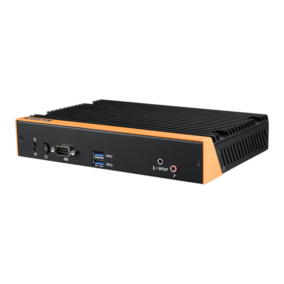
Page 18: Ds-580 Front And Rear Views
Figure 2.2 Rear view DS-580 Front External I/O Connectors 2.2.1 Power ON/OFF Button DS-580 has a power ON/OFF button on front side. Push this button to turn the sys- tem ON and OFF. Figure 2.3 Power button DS-580 User Manual... -
Page 19: Com Connector
2.2.3 USB Connectors DS-580 front side provides 2 x USB3.0 interface connectors, which give complete Plug & Play and hot swapping capability for up to 127 external devices. The two USB 3.0 interface are compliant with USB UHCI, Rev. 3.0. (Refer to Table 2.2 for pin defi- nitions) Figure 2.5 USB connector... -
Page 20: S/Pdif / Line Out
The connector port have Microphone (Input) functions. Figure 2.7 Mic-in connector DS-580 Rear External I/O Connectors 2.3.1 Power Input Connector DS-580 comes with a DC-Jack header that takes 19 VDC external power input. Figure 2.8 DC input connector DS-580 User Manual... -
Page 21: Hdmi Connector
2.3.2 HDMI Connector DS-580 HDMI (High-Definition Multimedia Interface) connectors provide all-digital audio/video interface to transmit the uncompressed audio/video signals and are HDCP compliant. Connect the HDMI audio/video device to this port. HDMI technol- ogy can support a maximum resolution of 3840 x 2160p (Ultra HD 4K) but the actual resolutions supported depend on the monitor being used. -
Page 22: Usb Connectors
2.3.3 USB Connectors DS-580 rear side provides 2 x USB2.0 interface connectors, which give complete Plug & Play and hot swapping capability for up to 127 external devices. (Pin definition refer Table 2.4) Figure 2.10 USB 2.0 connector Table 2.4: USB Pin Assignments... -
Page 23: Ethernet Connector (Lan)
2.3.4 Ethernet Connector (LAN) DS-580 provides two RJ45 LAN interface connectors,they are fully compliant with IEEE 802.3u 10/100/1000 Base-T standards. The Ethernet port provides a standard RJ-45 jack connector with LED indicators on the front side to show its Active/Link sta- tus and speed status. -
Page 24: Hardware Installation
Loosening the 4 fixing screws ① on the top cover ② . Remove the top cover ② . Insert the memory module into memory socket ④⑤ . Assemble back the heatsink cover with the 4 screws. Figure 2.12 Memory module installation DS-580 User Manual... -
Page 25: Hdd/Ssd Installation
Loosening the 2 screws ② on the side view and move out the drive bay. Fixing the 4 screws ① with HDD/SSD and storage bracket. Insert the storage bracket into chassis. Fixing the screw back. Figure 2.13 HDD/SSD installation DS-580 User Manual... -
Page 26: Mini Pcie Card /Sim Card Installation
Figure 2.14 Mini PCIe / SIM card installation 2.4.4 Antenna Installation Loosening the 4 fixing screws ① on the side of top cover. Attach the antenna module to the ant holes ② of chassis. Assemble back the top cover with the screws. DS-580 User Manual... -
Page 27: Installation
M.2 Installation Loosening the 4 fixing screws ① on the top cover ② . Remove the top cover ② . Insert the M.2 module into M.2 socket ③ . Assemble back the heatsink cover with the 4 screws. DS-580 User Manual... -
Page 28: Mount Brackets Installation
Figure 2.16 M.2 module installation 2.4.6 Mount Brackets Installation Fixing the two mount brackets with 4 screws M3x5L ① directly. DS-580 User Manual... -
Page 29: Rubber Feet Installation
Figure 2.17 Mount brackets installation 2.4.7 Rubber Feet Installation Retrieve the four rubber feet from the accessory box. Attach the rubber feet to the four corners and fixing them by four screws ① directly. DS-580 User Manual... - Page 30 Figure 2.18 Rubber feet Installation DS-580 User Manual...
-
Page 31: Chapter 3 Bios Settings
Chapter BIOS settings This chapter explains the BIOS configuration process. -
Page 32: Bios Introduction
Using the AMI BIOS Setup program, users can modify the BIOS settings and control various system features. This chapter describes the basic navigation of the BIOS setup screens for the DS-580 series. The AMI BIOS's ROM features a built-in setup program that allows users to modify the basic system configuration. -
Page 33: Advanced Bios Setup
Figure 3.2 Advanced BIOS setup screen ACPI Settings System ACPI Parameters – Enable ACPI Auto Configuration – Enable Hibernation – ACPI Sleep State – Lock Legacy Resources DS-580 User Manual... - Page 34 Figure 3.3 ACPI setup screen SMART Settings System SMART Settings – SMART Self Test Run SMART Self test on all HDDs during POST Figure 3.4 SMART Setting screen DS-580 User Manual...
- Page 35 ITE8528E Super I/O Configuration System super I/O chip parameters Figure 3.5 Super I/O configuration setup screen ITE8528E HW Monitor Hardware status (PC health) monitoring Figure 3.6 Hardware monitoring screen DS-580 User Manual...
- Page 36 S5 RTC Wake Settings Enable the system to wake from S5 using a real-time clock (RTC) alarm Figure 3.7 S5 RTC wake setup screen Serial Port Console Redirection Figure 3.8 Serial port console redirection setup screen DS-580 User Manual...
- Page 37 CPU Configuration CPU configuration parameters Figure 3.9 CPU configuration setup screen PPM Configuration Enable/disable CPU C-state report to OS Figure 3.10 CPU C-state report setup screen DS-580 User Manual...
- Page 38 Allows users to set the USB mass storage device start unit command timeout time; options include 10, 20, 30, and 40 seconds. – Device Power-Up Delay Enable/disable Auto or Manual USB mass storage device start unit command timeout. DS-580 User Manual...
- Page 39 Figure 3.12 USB configuration setup screen Platform Trust Technology Figure 3.13 Platform Trust Technology Security Configuration Intel® Anti-Theft Technology configuration DS-580 User Manual...
-
Page 40: Bios Chipset Setup
Figure 3.14 Intel TXE configuration setup screen 3.2.3 BIOS Chipset Setup Select the Chipset tab in the DS-580 BIOS Setup Utility to enter the BIOS Chipset setup screen. Users can select any item displayed in the left frame of the screen. ... -
Page 41: Bios Security Setup
Figure 3.15 North Bridge and South Bridge setup scree 3.2.4 BIOS Security Setup Select the Security tab from the setup screen to enter the BIOS Security setup screen Administrator Password Set an administrator password User Password Set a user password DS-580 User Manual... -
Page 42: Bios Boot Setup
Figure 3.16 Security configuration setup screen 3.2.5 BIOS Boot Setup Select the Boot tab from the DS-580 setup screen to enter the BIOS Boot setup screen. Users can select any item in the left frame of the screen. Figure 3.17 Boot configuration setup screen... -
Page 43: Bios Save & Exit Setup
Save Changes and Reset Reset the system after saving changes Discard Changes and Reset Reset the system without saving changes Save Changes Save changes to all setup options Discard Changes Discard changes to all setup options DS-580 User Manual... - Page 44 Restore the User Defaults to all setup options Boot Override – UEFI Built-in EFI Shell – Launch EFI Shell From File System Device Allows users to launch the EFI Shell application (Shell.efi) from an available file system device DS-580 User Manual...
- Page 45 DS-580 User Manual...
- Page 46 No part of this publication may be reproduced in any form or by any means, such as electronically, by photocopying, recording, or otherwise, without the prior written permission of the publisher. All brand and product names are trademarks or registered trademarks of their respective companies. © Advantech Co., Ltd. 2019...
Need help?
Do you have a question about the DS-580 and is the answer not in the manual?
Questions and answers