
Related Manuals for Advantech DLoG DLT-V7210 P


Summary of Contents for Advantech DLoG DLT-V7210 P
- Page 1 Operating Instructions DLT-V72 Series Industrial Computer Operating Instructions V2.50 (EN)
- Page 2 Note regarding all links and website content included in this document: Advantech Co., Ltd. is not responsible for the accessibility of the websites and for the content of external links contained in this document. The content and accessibility of the linked websites are the sole responsibility of their operators.
- Page 3 − Retain all documents and pass them on to any future owners of the equipment. − Read and observe the “DLT-V72 Operating Instructions” available online and provided for download from our websites: www.advantech.com www.advantech-service-iot.eu On our websites you will also find the latest versions of all DLT-V72 documentation.
- Page 4 INTENDED USE DLT-V72 Industrial Computers are data communication terminals for use in commercial industries such as logistics, warehousing and manufacturing. Any other or additional use beyond this is regarded as improper use. DLT-V72 Industrial Computers are only permitted to be operated: −...
- Page 5 REQUIREMENT FOR COMMISSIONING AND OPERATING PERSONNEL Requirements for commissioning and maintenance Work such as commissioning and maintaining the DLT-V72 is only permitted to be performed by skilled personnel who have specialist vocational training and who have up-to-date knowledge and experience in the area of work in question. Examples: −...
- Page 6 − If battery packs from other manufacturers are inserted in the DLT-V72, the warranty for this device will be rendered void. − The battery packs must be certified for the DLT-V72. − Do not use battery packs from any other Advantech devices; they are not compatible.
- Page 7 Prevent physical damage due to deep discharge. Storing the battery packs incorrectly will cause them to discharge completely (deep discharge) and thus damage them irreparably. To prevent a deep discharge: − Remove the battery pack from the battery pocket, if the DLT-V72 is not used for a longer period of time (more than one month).
- Page 8 INFORMATION ON SAFE MOUNTING During the mounting process The DLT-V72 can fall down and cause injuries due to its weight. − Use the assistance of a second person for installation work. − Always hold the DLT-V72 by the housing with both hands. −...
- Page 9 − Only connect or disconnect electrical connections when the device is in a de-energized state. − Use only original Advantech power supply cables; these meet the specific requirements for low-temperature flexibility, UV resistance, oil resistance, etc. Installing the disconnecting device The DLT-V72 is not equipped with disconnecting devices that are accessible from the outside;...
- Page 10 SAFETY DURING ONGOING WORK OPERATIONS Requirements for the operating personnel Users of the DLT-V72 must be trained by skilled personnel and instructed in the operation of the device. All users must be familiar with all functions of the product they come into contact with.
- Page 11 REGULAR MAINTENANCE WORK General To avoid damage to the DLT-V72 and to ensure safe functioning: − Depending on the load and environmental conditions, check at least once per month, and more often if necessary, that all connected cables are secured and that the cable cover is tightly sealed (important for IP protection against dust, etc.).
- Page 12 Accessories and peripherals Accessories and peripherals may only be installed or integrated if expressly approved by Advantech for the respective DLT-V72. If other parts are attached or installed and connected, claims for warranty and / or product liability will be lost.
-
Page 13: Table Of Contents
Table of contents 1. INTRODUCTION........................7 1.1. Information about the DLT-V72 manuals ......................7 1.1.1. Current manual versions at our websites ........................7 1.1.2. ONE manual for all device models ..........................7 1.2. Warnings and notes in the operating instructions ....................8 2. - Page 14 10.3. Preparation work at the factory ........................49 10.4. Customer-specific settings ..........................50 10.5. Windows Zero Configuration (WZC) ........................ 50 10.6. Advantech WLAN Client Manager (IGX Tool) ....................51 10.6.1. Area of application ..............................51 10.6.2. After image reinstallation: Driver installation ......................51 10.6.3.
- Page 15 12.3. Mounting the DLT-V72 at the deployment location ..................85 12.3.1. Electrically isolated DLT-V72 mounting ........................86 12.4. Attaching accessories to the DLT-V72 ......................87 12.4.1. VESA mounting hole pattern ............................ 87 12.4.2. Attach the mounting bracket ............................ 88 12.4.3. Attach accessories ..............................88 13.
- Page 16 18. REASONABLY FORESEEABLE MISUSE................115 19. GUIDELINES AND CERTIFICATES ..................116 19.1. Simplified EU declaration of conformity ......................116 19.2. USA/CANADA ..............................116 19.3. CCC, SRRC China ............................117 19.4. CNROHS ................................ 118 19.5. Taiwan ................................118 20. END-OF-LIFE DEVICE DISPOSAL ..................119 21.
-
Page 17: Introduction
DLT-V72. Keep the manuals for future use. Please contact Advantech if you require additional information or clarification. You can find the contact address in section Technical customer support. 1.1.1. Current manual versions at our websites The latest versions of our manuals are available at our websites: www.advantech.com... -
Page 18: Warnings And Notes In The Operating Instructions
Introduction 1.2. Warnings and notes in the operating instructions Personal injury Information with regard to personal injury is shown as follows (signal words for indicating risk level): DANGER / WARNING / CAUTION DANGER means that death or severe bodily injury will occur if this information is not observed. WARNING means that death or severe bodily injury can occur if this information is not observed. -
Page 19: Technical Customer Support
Technical customer support Technical customer support Contact your distributor, sales representative, or an Advantech Service Center for technical support. Please have the following information ready: − Product name − Serial number − Description of your peripheral attachments − Description of your software (operating system, application software, etc.) −... -
Page 20: Functional Description
Functional description Functional description 3.1. Intended use DLT-V72 Industrial Computers are data communication terminals for use in commercial industries such as logistics, warehousing and manufacturing. Any other or additional use beyond this is regarded as improper use. DLT-V72 Industrial Computers are only permitted to be operated: −... -
Page 21: Mount, Operate And Service The Device Correctly
Do not damage the name plate or remove it from the device. Information on the labels on the device (examples): − Model name − Serial number − FCC ID (Radio) − Barcode (for Advantech-internal use only) DLT-V72 Operating Instructions V2.50 11 / 121... -
Page 22: Unpacking, Transporting, Storing
Unpacking, transporting, storing Unpacking, transporting, storing 4.1. Packing list Before setting up the system, check that the items listed below are included and in good condition. If any item does not accord with the table, please contact your dealer immediately: −... -
Page 23: Storage
Unpacking, transporting, storing 4.4. Storage Observe the permissible storage temperature range in the manual, section 5.2 Environmental conditions. Observe the “DLT-V72 Safety Instructions” regarding DLT-V72 devices with integrated UPS. WARNING Personal injury due to short-circuit, fire, chemical burns, toxic substances. Devices with integrated UPS (optional) contain lithium-ion battery packs. -
Page 24: Technical Data - Device
Technical data – Device Technical data – Device 5.1. General ® Intel ATOM™ E3845 Quad Core 1.91 GHz Processor Chipset Dual channel 1333 MHz memory bus speed Cache 2 MB L2 cache, 22 nm 4 GB RAM DDR3L Technology BIOS AMI Aptio UEFI;... - Page 25 Technical data – Device NOTICE: Property damage Protect the display of the DLT-V72 from the memory effect. The display of the DLT-V72 has to be protected from the burning in of a motionless image. An image that has remained motionless for too long can cause irreversible damage to the display. Recommendation: ...
-
Page 26: Environmental Conditions
Technical data – Device 5.2. Environmental conditions 5.2.1. DLT-V72 without integrated UPS Operating temperature -30 to +50 °C Specification according to EN 60068-2-1/2 Storage temperature -30 to +65 °C Specification according to EN 60068-2-1/2 Relative humidity 10% to 90% at 40 °C relative humidity Noncondensing Specification according to EN 60068-2-3 Mechanical vibration... -
Page 27: Device Dimensions
Technical data – Device 5.3. Device dimensions 5.3.1. DLT-V7210 P, R, D Dimensions without add-ons (in mm) Fig. 5.1: Dimensions DLT-V7210 P, R, D 5.3.2. DLT-V7212 P, R, D Dimensions without add-ons (in mm) Fig. 5.2: Dimensions DLT-V7212 P, R, D DLT-V72 Operating Instructions V2.50 17 / 121... -
Page 28: Dlt-V7210 K, Kd
Technical data – Device 5.3.3. DLT-V7210 K, KD Dimensions without add-ons (in mm) Fig. 5.3: Dimensions DLT-V7210 K, KD 5.3.4. DLT-V7212 P+ Dimensions without add-ons (in mm) Fig. 5.4: Dimensions DLT-V7212 P+ 18 / 121 DLT-V72 Operating Instructions V2.50... -
Page 29: Vesa Drill Holes
Technical data – Device 5.4. VESA drill holes The back of the DLT-V72 has a VESA-compatible 75 x 75 mm mounting hole pattern. It is used to attach VESA- compatible mountings to mount the DLT-V72 at the deployment location. Depth of thread: M6 x 6mm NOTICE: Property damage Only use mountings and mounting materials that have been tested and approved for the respective DLT-V72. -
Page 30: Technical Data - Radio Modules (Optional)
Technical data – Radio modules (optional) Technical data – Radio modules (optional) 6.1. Identification of the equipment variants The DLT-V72 offers numerous radio equipment variants for WLAN, WWAN, GNSS and Bluetooth. To identify the variant installed in your device, proceed as follows: −... -
Page 31: Radio Card For Wwan
Technical data – Radio modules (optional) 6.2.2. Radio card for WWAN USA: QUECTEL EC25A Europe: QUECTEL EC25E Card type WWAN PCIe Full-Mini Card Technology WWAN 2G, 3G, 4G cellular bands and GNSS FCCID FCC ID: XMR201605EC25A (valid for the EC25-A variant) Maximum transmitting power Class 3 (23dBm±2dB) for LTE FDD Class 3 (23dBm±2dB) for LTE TDD... -
Page 32: Antennas (Optional)
Technical data – Radio modules (optional) 6.3. Antennas (optional) 6.3.1. WLAN antenna IEEE 802.11 a/b/g/n/ac Fig. 6.1: WLAN antenna IEEE 802.11 a/b/g/n/ac Technical data Application WLAN a/b/g/n/ac Dual Band with MRC Bluetooth (integrated via Radio card) WLAN frequency range Band 1: 2400 to 2485 MHz Band 2: 5150 to 5850 MHz Bluetooth features See section 6.4.1 Bluetooth... -
Page 33: Wlan, Wwan, Lte 4G Antenna (Multiband)
Technical data – Radio modules (optional) 6.3.2. WLAN, WWAN, LTE 4G antenna (Multiband) Fig. 6.2: WLAN, WWAN, LTE 4G antenna (Multiband) Technical data Application WLAN IEEE 802.11 ac/a/b/g/n Dual Band with MRC WWAN 4G Bluetooth 4.2+HS WLAN frequency range Band 1: 2400 to 2485 MHz Band 2: 5150 to 5875 MHz WWAN frequency bands FDD LTE: B1/B3/B5/B7/B8/B20... -
Page 34: External Wlan Antenna Ieee 802.11 A/B/G/N
Technical data – Radio modules (optional) 6.3.3. External WLAN antenna IEEE 802.11 a/b/g/n Fig. 6.3: External WLAN antenna Technical data Application WLAN IEEE 802.11 a/b/g/n Dual Band Mounting location For detached mounting, e.g. on the roof of the forklift WLAN frequency range Band 1: 2400 to 2485 MHz Band 2: 5150 to 5875 MHz Number of antennas... -
Page 35: External Wwan Antenna 2G, 3G, 4G
Technical data – Radio modules (optional) 6.3.4. External WWAN antenna 2G, 3G, 4G Fig. 6.4: External 2G, 3G, 4G WWAN antenna Technical data Application WWAN 2G, 3G, 4G cellular bands Mounting location For detached mounting, e.g. on the roof of the forklift Number of antennas Type Omnidirectional antenna... -
Page 36: Bluetooth
The GPS receiver has an integrated antenna for position data of the Global Positioning System (GPS) and communicates with the DLT-V72 via USB interface. We recommend using only a GPS receiver approved by Advantech. Fig. 6.5: External GPS receiver (optional) Installation The installation CD supplied with the GPS receiver includes installation files and a multi-lingual manual. -
Page 37: Connectors
Connectors Connectors 7.1. Connectors under the cable cover Fig. 7.1: External connectors under the cable cover Pin assignment Power supply 12/24/48 VDC nominal 1 x SMA (optional) Remote WWAN antenna 1 x RSMA (optional) Remote WLAN antenna USB0, USB1, USB2, USB3 USB 2.0 interfaces (HI-SPEED™), bootable Fused at 1.0 A per channel ESD Level 4 protected (according to EN 61000-4-2) -
Page 38: Network Adapter (10/100/1000)
Connectors 7.1.2. Network adapter (10/100/1000) The DLT-V72 is equipped with a 10/100/1000 Mbit network adapter with 10/100/1000 Mbit per second. This adapter can be accessed via the bottom of the device and offers an RJ45 connection jack. The RJ45 connection port has two integrated status LEDs and are assigned as follows: Left LED (green): Right LED (orange): LED off: no connection... -
Page 39: Connectors Under The Antenna Or Protective Cap
Connectors 7.2. Connectors under the antenna or protective cap The following connectors can be found under the DLT-V72 antenna or under the protective cap (for devices without radio equipment): − Service-USB (USB 3.0 Host, SUPERSPEED − CFast-Slot − Mini-SIM card slot (optional) NOTICE: Property damage −... -
Page 40: Open/Close The Wlan Antenna Ieee 802.11 A/B/G/N/Ac
Connectors 7.4. Open/close the WLAN antenna IEEE 802.11 a/b/g/n/ac Tools required: − Torx screwdriver, Tx20 − Allen key (size 7) Opening the antenna cap: Unfasten both screws on the antenna cap. Remove the antenna cap from the device. Fig. -
Page 41: Open/Close The Wlan, Wwan, Lte 4G Antenna
Connectors 7.5. Open/close the WLAN, WWAN, LTE 4G antenna Tools required: − Torx screwdriver, Tx20 − Allen key (size 7) Opening the antenna cap: Unfasten both screws on the antenna. Remove the antenna carefully. The antenna module is located underneath the antenna cap: Fig. -
Page 42: Operation
Operation Operation 8.1. Safety during ongoing work operations WARNING Personal injury, Property damage and downtimes due to improper operation Requirements for the operating personnel Users of the DLT-V72 must be trained by skilled personnel and instructed in the operation of the device. All users must be familiar with all functions of the product they come into contact with. -
Page 43: Switching The Dlt-V72 On/Off
Operation 8.2. Switching the DLT-V72 on/off The following factors determine how the DLT-V72 can be switched on and off: − Is the DLT-V72 mounted on a vehicle and connected with the ignition signal? − What are the automatic shutdown settings that were defined in the “DLoG Config” program? Switch on Switch the DLT-V72 on as follows, depending on the configuration: ... -
Page 44: Operating The Touchscreen
Operation 8.3. Operating the touchscreen All touchscreens can be operated with: − Clean, dry fingers − Clean, dry gloves − Suitable touch stylus: Resistive touchscreens: touch stylus plastic or wood, rounded tip PCT touchscreens: touch stylus with capacitive (electrically conductive) tip Prevent damage to the touchscreen Valid for all touchscreen versions: Resistive and PCT! ... -
Page 45: Operation Elements
Operation 8.4. Operation elements 8.4.1. Note on the backlight function on/off The DLT-V72 will continue to react to keyboard, mouse and touchscreen inputs even if the backlight is switched off. 8.4.2. Rear side DLT-V72 Operating Instructions V2.50 35 / 121... -
Page 46: Front Side: Dlt-V7210 P, R, D And Dlt-V7212 P, R, D
Operation 8.4.3. Front side: DLT-V7210 P, R, D and DLT-V7212 P, R, D 36 / 121 DLT-V72 Operating Instructions V2.50... -
Page 47: Front Side: Dlt-V7212 P
Operation 8.4.4. Front side: DLT-V7212 P+ DLT-V72 Operating Instructions V2.50 37 / 121... -
Page 48: Front Side: Dlt-V7210 K, Kd
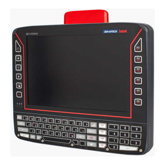
Operation 8.4.5. Front side: DLT-V7210 K, KD 38 / 121 DLT-V72 Operating Instructions V2.50... -
Page 49: Integrated Keyboard
Operation 8.4.6. Integrated keyboard 8.4.6.1. Language variants The integrated keyboard of the DLT-V7210 K is available in three languages: − English − German − French The integrated keyboard of the DLT-V7210 KD is available in English. Example English version (QWERTY) Fig. -
Page 50: Abb. 8.3: Integrated Keyboard French (Azerty)
Operation German „Umlaute“ Umlaut Press the keys successively: ä + V + A Ä + V + A ö + V + O Ö + V + O ü + V + U Ü + V + U 8.4.6.4. Integrated keyboard French (AZERTY) features Abb. -
Page 51: Operating States
Operation 8.5. Operating states Status of LEDs Supply voltage Temperature DLT-V72 status Initial state, idle time – waiting for a new ignition signal or for the <Power> key after switch-off; no voltage supply FLASHING Temperature sensor faulty FLASHING DLT-V72 is in standby mode (S3) Computer will only start if the temperature in the device is in the range between -30 and +59 °C again. -
Page 52: Software Keyboard (Optional)
Fig. 8.4: Software keyboard If the software keyboard was ordered together with the DLT-V72 industrial PC, then the program will have been fully pre-licensed by the Advantech production department. For subsequent installation, an installation program is available. The “DLoG software keyboard manual” is available on our websites. -
Page 53: Operating The Dlt-V72 With Ups
Operation 8.7. Operating the DLT-V72 with UPS WARNING Personal injury due to short-circuit, fire, chemical burns, toxic substances. DLT-V72 devices with integrated UPS contain lithium-ion battery packs. These can ignite if handled or stored improperly (risk of fire), cause chemical burns or release toxic substances. ... -
Page 54: General Device Configuration
General device configuration General device configuration 9.1. Operating systems (optional) Please find the latest overview of all supported operating systems in the DLT-V72 data sheets on our websites. The following operating systems are available at the time of manual creation, June 2019: −... -
Page 55: Energy Options And Battery Pack Durability
General device configuration 9.2.3. Energy options and battery pack durability Valid for all MS Windows operating systems: NOTICE: Property damage All DLT-V72 devices with MS Windows have had the power options set at the factory so that the optimal duration of the battery pack can be achieved: The power saving plan is set to power options (DLoG). -
Page 56: Linux (Optional)
General device configuration 9.3. Linux (optional) The configuration of the DLT-V72 with Linux with regard to radio networks, touchscreen calibration, etc. is described in the “Advantech Linux Manual”. Please contact our Technical Customer Support if required. 9.4. USB Recovery Stick The optional recovery stick allows images to be backed up and restored onto the DLT-V72 when necessary (backup &... - Page 57 Automatic shutdown configuration Configuration description DLT-V72 with MS-Windows OS „DLoG Config Manual“. Available on our Websites DLT-V72 with Linux OS „Advantech Linux Manual“. Please contact our Technical Customer Support if required DLT-V72 Operating Instructions V2.50 47 / 121...
-
Page 58: 10. Wlan Configuration
Antenna solutions for use in Germany The Advantech antenna solutions are based on the prevailing IEEE 802.11 standard. This standard allows radio data transfer at rates from 1 Mbps to 54 Mbps (867 Mbit/s if using IEEE 802.11ac) using the 2.4 GHz and 5 GHz frequency band. -
Page 59: Configuration Differences Between Ms Windows And Linux
The radio configuration of the DLT-V72 with MS Windows operating system is described in the following manual sections. The radio configuration of the DLT-V72 with Linux is described in the “Advantech Linux Manual”. Please contact our Technical Customer Support if required. -
Page 60: Customer-Specific Settings
Use the configuration program that is already factory-installed on the DLT-V72. Observe the description of the configuration programs in the following sections. Radio card Operating Configuration program system Advantech WLAN Client Manager (IGX Tool) Password: gold Qualcomm Atheros SPARKLAN Windows QCA61x4A Wireless Wireless Zero Configuration (abbreviation: WZC) -
Page 61: Advantech Wlan Client Manager (Igx Tool)
WLAN configuration 10.6. Advantech WLAN Client Manager (IGX Tool) 10.6.1. Area of application This chapter describes the Advantech WLAN Client Manager program version 1.00 under the following operating systems: − Win7Pro − WinEmbStd7 − Win8.1IndPro − Win10IoTEnt This chapter applies to DLT-V72 devices with the Radio card "SPARKLAN WPEQ-261ACN(BT) MiniPCIe". -
Page 62: 10.6.4. Driver Installation Winembstd7
WLAN configuration 10.6.4. Driver installation WinEmbStd7 If it is not known which operating system variant (32 or 64 bit) is installed on the DLT-V72, the system overview can be used for testing: Fig. 10.1: System overview in Control Panel For 32 bit systems: ... -
Page 63: Fig.10.2: Setup.exe For 64 Bit Operating System In The Subfolder Win7_X64
WLAN configuration Example screenshot for 64 bit system, subfolder Win7_X64: Fig.10.2: Setup.exe for 64 bit operating system in the subfolder Win7_X64 NOTE The remaining installation workflow is covered in the next chapter and is identical in all operating systems. DLT-V72 Operating Instructions V2.50 53 / 121... -
Page 64: 10.6.5. Driver Installation Win7Pro / Win 8.1 Indpro / Win 10 Iot
WLAN configuration 10.6.5. Driver installation Win7Pro / Win 8.1 IndPro / Win 10 IoT Open the corresponding installation directory depending on the operating system. Run Setup.exe to start the installation. NOTE The following installation example shows the Win8.1 / 10 driver. For Windows7 installation, please use the corresponding Win7 driver. -
Page 65: Fig.10.4: Igx Driver Installation Welcome Dialog
WLAN configuration On completion, the following window is displayed that starts the actual driver installation process: Fig.10.4: IGX driver installation Welcome dialog Continue the installation with Next: Fig.10.5: IGX driver installation user and company name In this dialog, enter a username and a company name and confirm with Next. DLT-V72 Operating Instructions V2.50 55 / 121... -
Page 66: Fig.10.6: Igx Driver Installation All Program Features
WLAN configuration Fig.10.6: IGX driver installation All program features Leave the Complete option enabled. Continue the installation with Next. Fig.10.7: IGX driver installation starts Continue the installation of the required files with Install. 56 / 121 DLT-V72 Operating Instructions V2.50... -
Page 67: Fig.10.8: Igx Driver Installation Windows Security
WLAN configuration During installation, the following window is opened: Fig.10.8: IGX driver installation Windows Security Ensure that the Always trust software from… option has been selected. Continue the driver installation with Install. Fig.10.9: IGX driver installation Exit with Finish ... -
Page 68: Fig.10.10: Igx Driver Installation Perform Computer Re-Start
WLAN configuration The system re-start is carried out. Fig.10.10: IGX driver installation Perform computer re-start 58 / 121 DLT-V72 Operating Instructions V2.50... -
Page 69: 10.6.6. Start Wlan Client Manager, Login
WLAN configuration 10.6.6. Start WLAN Client Manager, Login Launch the WLAN Client Manager by double-clicking the Launch WCU icon: Fig.10.11: WCU icon on the desktop You must login as "WCU_Administrator" first. To do this, click Admin Login. Fig.10.12: WCU main window, Admin Login DLT-V72 Operating Instructions V2.50 59 / 121... -
Page 70: Fig.10.13: Wcu-Administrator Login Window
WLAN configuration Then open the login window. Enter the passport, which by default is "gold". Confirm the input with the Login button. Fig.10.13: WCU-Administrator login window 60 / 121 DLT-V72 Operating Instructions V2.50... -
Page 71: 10.6.7. Wlan Client Manager Functions
WLAN configuration 10.6.7. WLAN Client Manager functions 10.6.7.1. License The License function lists the current status of the enabled options: Fig.10.14: Check License NOTE The correct implementation of the WLAN driver requires a valid license in combination with the DLT-V72 terminal. -
Page 72: 10.6.8. Browse Nearby Wireless Networks
WLAN configuration 10.6.8. Browse nearby wireless networks 10.6.8.1. Set up the WLAN connection To set up a WLAN connection, you can show all available networks using the Browse nearby wireless networks function. You can select the appropriate network from here. Fig.10.16: Browse nearby wireless networks function 62 / 121 DLT-V72 Operating Instructions V2.50... -
Page 73: Fig.10.17: Advanced Security Settings Dialog
WLAN configuration 10.6.8.2. Define security settings The security settings must now be selected depending on the network. These settings can be made in the Advanced Security Settings section: Fig.10.17: Advanced Security Settings dialog To be able to connect with the network automatically, set the checkmark to connect automatically when the network is in range: Fig.10.18: Connection when the network is in range dialog DLT-V72 Operating Instructions V2.50... - Page 74 WLAN configuration Available parameters in the Connection and Security sections: Connection Connect automatically when the Enable this parameter to set up an automatic connection network is in range to the network. Connect to a more preferred network In the event of multiple profiles being present, this option if available can be used to select the preferred profile.
-
Page 75: Fig.10.19: Security Settings - Network Authentication Methods
WLAN configuration This results in the following selection options and settings: Fig.10.19: Security settings - network authentication methods The network authentication methods shown, as well as their designations, differ depending on the operating system used. DLT-V72 Operating Instructions V2.50 65 / 121... -
Page 76: Fig.10.20: Security Settings - Advanced Settings (Cisco: Leap)
WLAN configuration For the remaining settings as in the case shown above (Cisco: Leap), the required additional parameters are carried out using the two buttons Settings and Advanced settings. Fig.10.20: Security settings – Advanced settings (Cisco: Leap) Fig.10.21: Security settings – LEAP properties 66 / 121 DLT-V72 Operating Instructions V2.50... -
Page 77: Fig.10.22: Wireless Network Properties Dialog
WLAN configuration Lastly, the network key must be entered in the following example (WPA2-Personal) (Network Security Key). Confirm the settings with OK. Fig.10.22: Wireless Network properties dialog DLT-V72 Operating Instructions V2.50 67 / 121... -
Page 78: Fig.10.23: Create New Profile Dialog
WLAN configuration Fig.10.23: Create new profile dialog Confirm the new profile with the OK button. 68 / 121 DLT-V72 Operating Instructions V2.50... -
Page 79: Fig.10.24: Network Connection Is Established
WLAN configuration 10.6.8.3. Establish network connection After the WLAN profile settings have been made, a connection to the network is established automatically. The connection setup with the selected network is successful only if the "green" connection line is displayed in the WCU main window. -
Page 80: 10.6.9. Roam Management
WLAN configuration 10.6.9. Roam Management 10.6.9.1. General After clicking the General dialog, the following information is displayed on the screen: Fig.10.25: General dialog in the Roam Management menu General Info Meaning of the display Client Status Current connection status: Connected / Disconnected Network Name SSID SSID of the currently connected access points Network Type... -
Page 81: Fig.10.26: Roaming Dialog In The Roam Management Menu
WLAN configuration 10.6.9.2. Roaming The Roaming dialog is used to define the following parameters: Fig.10.26: Roaming dialog in the Roam Management menu Roam Signal Level (dBm): This setting defines when the client is to be begin the roaming process. Possible values: -55 dBm to -80 dBm Default value: -65 dBm (adjustable in 5 dBm increments) Minimum This setting defines how long the client is to remain connected to the current access... -
Page 82: Fig.10.27: Roam Management - Choose Band And Channels
WLAN configuration Firmware Logging Option can be enabled to create a "Firmware" log. The log file is saved to the C:\WlanLogs folder and is assigned the current timestamp and the extension _fw. If the log file is larger than 100 mb, a new file is created. NOTE: This option should only be enabled for short periods for analysis purposes, not permanently! Roam RSSI... - Page 83 WLAN configuration Channel List Select all 2.4Ghz This option can be used for simultaneous pre-selection of all 2.4 GHZ channels channels 1 to 13 supported by the WLAN driver. Modifications to individual channels can be carried out at any time by clicking the checkboxes for each channel.
-
Page 84: Fig.10.28: Radio Dialog In The Roam Management Menu
WLAN configuration 10.6.9.3. Radio Tab The Radio dialog is used to define the following parameters: Fig.10.28: Radio dialog in the Roam Management menu Power Save The Power Save Level is set. The levels OFF and Auto-PSM are available. Mode Selection The band of the client is specified. -
Page 85: Fig.10.29: Adapter Tab In Roam Management Menu
WLAN configuration 10.6.9.4. Adapter Tab After clicking the Adapter dialog, the following information is displayed on the screen: Fig.10.29: Adapter Tab in Roam Management menu DLT-V72 Operating Instructions V2.50 75 / 121... -
Page 86: 11. Wwan Configuration
WWAN configuration 11. WWAN configuration 11.1. Safety notes CAUTION Danger of radiation emission. DLT-V72 devices with radio technology emit high frequency energy (abbreviation: HF). To protect persons and domestic animals against HF radiation: Mount the DLT-V72 so that persons and domestic animals maintain a minimum distance of 20 to 50 cm from the radio antennas. -
Page 87: Preparation Work At The Factory (Dlt-V72 Delivery Status)
WWAN configuration 11.2. Preparation work at the factory (DLT-V72 delivery status) The following preparations have already been carried out at the factory for the optional WWAN functionality of the DLT-V72: − The WWAN card and the corresponding drivers are installed. −... -
Page 88: Configuration Of Radio Card Quectel Ec25
WWAN configuration 11.4. Configuration of Radio card QUECTEL EC25 The following information is valid for the Radio card QUECTEL EC25. Its precise designation is: − USA: QUECTEL EC25A or EC25V − Europe: QUECTEL EC25E The WWAN configuration is identical for both Radio cards. For this reason, the abbreviation QUECTEL EC25 is used. -
Page 89: Fig. 11.4: Quectel Ec25 - Connect To The Internet - Dial-Up
WWAN configuration Click Dial-up. Fig. 11.4: QUECTEL EC25 - Connect to the Internet - Dial-up Specify as a telephone number, e.g. *99***1#. Enter a connection name, e.g. Vodafone test connection. Username and password are not required in the example. (Provider- dependent) Fig. -
Page 90: Fig. 11.7: Quectel Ec25 - Dial Vodafone Test Connection
WWAN configuration Do not enter a user name or password. Click Dial. The test connection is established. Fig. 11.7: QUECTEL EC25 - Dial Vodafone test connection In the Network and activation center of the device, the status of the test connection can be tested: ... -
Page 91: Trouble Shooting
WWAN configuration 11.4.2. Trouble Shooting 11.4.2.1. Test virtual COM ports In the device manager it is possible to test that the virtual COM ports are correctly set. If they are not correctly set, they must be modified as appropriate. The virtual COM ports must be set up as shown in the figure: Fig. -
Page 92: Fig. 11.10: Quectel Ec25 - Test Nmea Data Flows
WWAN configuration 11.4.2.2. Test communication between DLT-V72 and WWAN Radio card The open source software Tera Term, for example, can be used to test that the DLT-V72 can communicate with the Radio card. This software can be downloaded from the following URL, for example (website available at time of writing this operating manual, dated May 2019): https://www.heise.de/download/product/tera-term-51776 Perform the following steps:... -
Page 93: 12. Mechanical Installation
Mechanical installation 12. Mechanical installation 12.1. Safety notes WARNING Risk of injury and damage due to improper mechanical installation. These mounting instruction are directed to skilled personnel. Only qualified skilled personnel may perform the mechanical installation work on the DLT-V72. If the DLT-V72 is incorrectly mounted, any warranty for this device will be void. -
Page 94: Overview: Recommended Mounting Sequence
Mechanical installation 12.2. Overview: Recommended mounting sequence Requirement: The vehicle/installation location must be prepared (e.g. connection to the ignition, correct voltage, etc.) − Find a suitable installation position for the DLT-V72. − Secure the device mounting (RAM or mounting bracket) to the targeted subject/vehicle. −... -
Page 95: Mounting The Dlt-V72 At The Deployment Location
Mechanical installation 12.3. Mounting the DLT-V72 at the deployment location WARNING Risk of injury and damage due to improper deployment location. Observe the intended use of the DLT-V72, e.g. not in potentially explosive areas, not in life-supporting facilities. Ensure that the deployment location of the DLT-V72 complies with the permissible environmental conditions. -
Page 96: Electrically Isolated Dlt-V72 Mounting
Mechanical installation 12.3.1. Electrically isolated DLT-V72 mounting DANGER Risk of accident on vehicles due to unexpected vehicle emergency stop because of electro- conductive connection of the DLT-V72 to the vehicle chassis. Due to a variety of technical properties of forklifts and forklift trucks, it can be necessary to electrically isolate DLT-V72 from the chassis of the vehicle to prevent malfunctions. -
Page 97: Attaching Accessories To The Dlt-V72
Observe the maximum screw-in depth of the hole of the mounting hole pattern: The recommended screw-in depth of Dx1 always applies (screw diameter x 1). − If you ordered a bracket from Advantech, it includes the suitable screws and washers. Please use them. NOTICE: Property damage Only use mounting brackets, accessories and mounting materials that have been tested and approved for the respective DLT-V72. -
Page 98: Attach The Mounting Bracket
Mechanical installation 12.4.2. Attach the mounting bracket The housing of the DLT-V72 has holes provided for attaching a mounting bracket. Screw-in depth: M6 x 6 mm Suitable mounting material: − Cylinder head screws DIN912 M6 − Washers DIN 125 - A 6.4 Fig. -
Page 99: 13. Electrical Installation, Cables, Cable Cover
Electrical installation, cables, cable cover 13. Electrical installation, cables, cable cover 13.1. Safety notes 13.1.1. General WARNING Risk of injury and damage due to improper electrical installation. These instructions are directed to skilled personnel. Only qualified skilled personnel are permitted to perform the electrical installation of the DLT-V72. ... -
Page 100: Power Cables And Fuses
WARNING Electric shock, fire due to incorrect cable routing or insufficient grounding. Use only original Advantech power cables; these meet the specific requirements for low-temperature flexibility, UV resistance, oil resistance, etc. Make sure that the power supply cables are run without kinks and are protected (securely protected against crushing and abrading). -
Page 101: Preparations
Electrical installation, cables, cable cover 13.2. Preparations Lay out ready all cables that are to be connected to the DLT-V72. Select the appropriate slots on the connector panel of the DLT-V72. Test in which order the cables best fit in the cable compartment. 13.3. -
Page 102: Tools
Electrical installation, cables, cable cover 13.3.4. Tools − Hexagon screwdriver, size 3 − Philips screwdriver, size 3 − Torque wrench − Allen wrench, size 2.5 − Flat head screwdriver, size 0 − Socket wrench, size 7 13.4. Procedure 13.4.1. Insert the rubber seal in the cable compartment ... -
Page 103: Ensure A Proper Electrical Connection
Electrical installation, cables, cable cover 13.4.2. Ensure a proper electrical connection Remove the nut from the ground bolt. The toothed washer remains on the ground bolt. Plug the ring tongue on the power supply cable onto the ground bolt; the flat side of the ring tongue points towards the DLT-V72 connector panel. -
Page 104: Secure The Power Supply Cable To The Strain Relief Rail
Electrical installation, cables, cable cover 13.4.4. Secure the power supply cable to the strain relief rail Mounting screws Open the round cable passage in the rubber seal. Insert the power supply cable. Place one cable clip on the power supply cable. ... -
Page 105: Close Off Unused Cable Openings
Electrical installation, cables, cable cover 13.4.6. Close off unused cable openings Close off all unused cable openings of the rubber seal using the accompanying blind plugs so that they are sealed. Fig. 13.7: Unused cable outlets sealed off with blind plugs 13.4.7. -
Page 106: Pressure Compensation Element
Electrical installation, cables, cable cover 13.5. Pressure compensation element The DLT-V72 cable cover has a pressure compensation element. Do not modify or remove the pressure compensation element; doing so would make the device leak and the IP protection would no longer be ensured. Fig. -
Page 107: 14. Integrated Power Supply, Power Supply Cable
Integrated power supply, power supply cable 14. Integrated power supply, power supply cable DLT-V72 is equipped with a galvanically separated, integrated DC power supply unit. Power is connected to the back of the unit using a Phoenix Contact plug. There is no power switch. Fig. -
Page 108: Dc Voltage Supply Connection
Integrated power supply, power supply cable Power consumption DLT-V7210 (all model types) Typically 25 W; Standby typically 1 W DLT-V7212 (all model types) Typically 30 W; Standby typically 1 W Power supply unit fuses Power supply unit Fuse type Example DC-16 5 x 20 mm T 12,5 A Schurter 0001.2515... -
Page 109: Dc Power Supply Cable
DC Power supply cable WARNING Electric shock, fire due to incorrect power supply cable. Use only original Advantech power supply cables; these meet the specific requirements for low- temperature flexibility, UV resistance, oil resistance, etc. Fig. 14.3: DC connection cable assignment DLT-V72 Operating Instructions V2.50... -
Page 110: 15. Optional Equipment
Optional equipment 15. Optional equipment 15.1. Integrated UPS (optional) The DLT-V72 is optionally available with an integrated uninterrupted power supply (UPS). The battery pack (lithium-ion technology) of the UPS is located in the battery pocket up top on the device. Fig. -
Page 111: Charging The Battery Pack
The battery packs must be authorized/approved for the DLT-V72. Do not use battery packs from any other Advantech devices; they are not compatible. If battery packs from other manufacturers are inserted in the DLT-V72, the warranty provided by Advantech for this device will be rendered void. -
Page 112: Fig. 15.2: Inserting The Battery Pack In The Battery Pocket
Optional equipment Procedure for opening the battery cover IMPORTANT: Switch off the DLT-V72. Loosen the two screws of the battery cover using an Allen wrench. Remove the battery cover. Remove the battery pack. Insert the new battery pack into the battery pocket as shown in the figure. ... -
Page 113: Screen Defroster (Optional)
Requirements: Screen Blanking sensor stick and Screen Blanking software, both optional. 15.4. USB recovery stick (optional) The optional Advantech recovery stick allows images to be backed up and restored onto the DLT-V72 when necessary (backup & recovery). DLT-V72 Operating Instructions V2.50... -
Page 114: Keyboards And Keyboard Mounts (Optional)
Optional equipment 15.5. Keyboards and keyboard mounts (optional) Any USB keyboard can be connected to the DLT-V72. Advantech offers the following keyboards: − SMALL keyboard − Mountable − Protection class IP65 − Keyboard layouts: German, English, French Fig. 15.3: SMALL keyboard −... -
Page 115: Scanner And Scanner Bracket (Optional)
Optional scanner brackets are available for the DLT-V72. Fig. 15.6: Example scanner bracket 15.7. Touch stylus Advantech offers some touch stylus pens (with associated mountings) for resistive and PCT touchscreens. Use only touch stylus that have been approved by Advantech. Touch stylus with mounting... -
Page 116: Protective Film For Touchscreen (Optional)
Optional equipment 15.8. Protective film for touchscreen (optional) An optional protective film is available for DLT-V72 touchscreens. This film protects the touchscreen during extreme use. NOTICE: Property damage Do not attach the protective film to damaged or worn out touchscreens. Air bubbles can get trapped and cause malfunctions. -
Page 117: 16. Maintenance
Advantech Service Centers. Accessories and peripherals Accessories and peripherals may only be installed or integrated if expressly approved by Advantech for the respective DLT-V72. If other parts are attached or installed and connected, claims for warranty and / or product liability will be lost. -
Page 118: Replacing The Integrated Keyboard Of The Dlt-V7210 K, Kd
Maintenance 16.2. Replacing the integrated keyboard of the DLT-V7210 K, KD If necessary, the integrated keyboard of the DLT-V7210 K, KD can be removed and replaced by a new keyboard (only by skilled personnel). WARNING Hazardous voltage, electric shock from contact with live parts. To prevent an electric shock: ... -
Page 119: Attach The Integrated Keyboard (Example)
Maintenance 16.2.2. Attach the integrated keyboard (example) Reuse: − Keyboard grid, black New, replacement parts: − Silicon keyboard mat − 5 x screws ISO14580-m3x8 A2 Fig. 16.2: Integrated keyboard: Keyboard components Procedure − Place the silicon keyboard mat on the circuit board. -
Page 120: Fig. 16.5: Integrated Keyboard: Attach Keyboard Grid
Maintenance Fig. 16.5: Integrated keyboard: Attach keyboard grid Use a TX10 screwdriver to tighten the 5 mounting screws of the integrated keyboard. Tightening torque: Maximum 2 Nm. 110 / 121 DLT-V72 Operating Instructions V2.50... -
Page 121: Regular Maintenance Work
Maintenance 16.3. Regular maintenance work 16.3.1. General To avoid damage to the DLT-V72 and to ensure safe functioning: Depending on the load and environmental conditions, check at least once per month, and more often if necessary, that all connected cables are secured and that the cable cover is tightly sealed (important for IP protection against dust, etc.). -
Page 122: Replacing The Battery Pack
Maintenance 16.3.2. Replacing the battery pack See section 15.1 Integrated UPS (optional) 16.3.3. Replacing the optional touchscreen protective film NOTICE: Property damage Do not attach the protective film to damaged or worn out touchscreens. Air bubbles can get trapped and cause malfunctions. The ordered optional protective film is normally attached to the DLT-V72 touchscreen at the factory. -
Page 123: 17. Malfunctions And Troubleshooting
Replace the battery pack. Use only original Advantech battery packs. No UPS functionality Battery pack is discharged Charge the battery pack properly. although battery pack is or deep discharged. - Page 124 Malfunctions and troubleshooting Software keyboard not License missing or invalid Enter the correct software license functioning Activate connection in the Control No WLAN connection Connection deactivated Panel AP access problem List ACL and check access rights to AP Invalid network settings Check WLAN, authorization parameters, network and protocol settings Signal strength too weak...
-
Page 125: 18. Reasonably Foreseeable Misuse
Reasonably foreseeable misuse 18. Reasonably foreseeable misuse Observe the intended use The DLT-V72 Industrial Computers are data communication terminals for use in commercial environments (e.g. logistics, warehousing, manufacturing). Do not use in the EX zone (potentially explosive), on ships and rail vehicles. ... -
Page 126: 19. Guidelines And Certificates
Comply with the provisions of the applicable EU directives, including their amendments applicable at the time of the declaration. For getting the detailed declarations of conformity please visit our websites and contact your regional person in charge: www.advantech.com / www.advantech.eu / www.advantech-service-iot.eu Shielded components All components connected to the DLT-V72, as well as cable connections must also meet the legal EMC requirements for compliance with the EMC legislation. -
Page 127: Ccc, Srrc China
Guidelines and certificates CAUTION Radio frequency exposure. In order to comply with the FCC requirements regarding radio frequency exposure from vehicle- mounted transmission devices: The antenna has to be kept at least 20 cm to 50 cm away from people and domestic animals. Any change or modification which is not expressly approved in the corresponding pages can lead to the withdrawal of the operating license for this device. -
Page 128: Cnrohs
Guidelines and certificates 19.4. CNROHS 19.5. Taiwan Numerous DLT-V72 models are approved for the Taiwanese market and carry the appropriate labeling on the device. 118 / 121 DLT-V72 Operating Instructions V2.50... -
Page 129: 20. End-Of-Life Device Disposal
End-of-life device disposal 20. End-of-life device disposal DLT-V72 devices and lithium-ion batteries are recyclable; they may not be disposed of with general/domestic waste. They must be disposed of properly in accordance with local regulations. Please contact the responsible authorities in your country/region to find out about the applicable regulations, if necessary. -
Page 130: List Of Figures
List of figures 21. List of figures Fig. 5.1: Dimensions DLT-V7210 P, R, D ..........................17 Fig. 5.2: Dimensions DLT-V7212 P, R, D ..........................17 Fig. 5.3: Dimensions DLT-V7210 K, KD ..........................18 Fig. 5.4: Dimensions DLT-V7212 P+ ........................... 18 Fig. -
Page 131: Dlt-V72 Operating Instructions V2.50
List of figures Fig. 11.9: QUECTEL EC25 - Virtual COM ports DLT-V72....................81 Fig. 11.10: QUECTEL EC25 - Test NMEA data flows ......................82 Fig. 12.1: VESA mounting hole pattern on the rear side of the DLT-V72 ................87 Fig. 12.2: Mounting bracket on the DLT-V72 ........................88 Fig.
Need help?
Do you have a question about the DLoG DLT-V7210 P and is the answer not in the manual?
Questions and answers