Table of Contents
Advertisement
Quick Links
Advertisement
Table of Contents

Related Manuals for Advantech DS-563SQ-S6A1E


Summary of Contents for Advantech DS-563SQ-S6A1E
- Page 1 DS-563SQ-S6A1E Computer/ 微型計算機 1 ...
- Page 2 The documentation and the software included with this product are copyrighted 2013 by Advantech Co., Ltd. All rights are reserved. Advantech Co., Ltd. reserves the right to make improvements in the products described in this manual at any time without notice.
-
Page 3: Declaration Of Conformity
Product Warranty (18 months) Advantech warrants to you, the original purchaser, that each of its products will be free from defects in materials and workmanship for two years from the date of purchase. This warranty does not apply to any products which have been repaired or altered by persons other than repair personnel authorized by Advantech, or which have been subject to misuse, abuse, accident or improper installation. -
Page 4: Technical Support And Assistance
Technical Support and Assistance Visit the Advantech website at www.advantech.com/support where you can find the latest information about the product. Contact your distributor, sales representative, or Advantech's customer service center for technical support if you need additional assistance. Please have the following information... - Page 5 Federal Communication Commission Interference Statement 15.105 Class B This equipment has been tested and found to comply with the limits for a Class B digital device, pursuant to Part 15 of the FCC Rules. These limits are designed to provide reasonable protection against harmful interference in a residential installation.
-
Page 6: Safety Instructions
DISCARD USED BATTERIES ACCORDING TO THE MANUFACTURER'S INSTRUCTIONS. The sound pressure level at the operator's position according to IEC 704-1:1982 is no more than 70 dB (A). RESTRICTED ACCESS AREA: The equipment should only be installed in a Restricted Access Area. DISCLAIMER: This set of instructions is given according to IEC 704‐1. Advantech disclaims all responsibility for the accuracy of any statements contained herein. 6 ... -
Page 7: Packing List
Packing List Before installation, please ensure the following items have been shipped: 1 x DS-565 Unit 1 x English User Manual 1x Accessory box Chapter 1 General Introduction This chapter gives background information on DS-565 series. 1.1 Introduction The DS‐565 is powered by Intel Cedarview‐M N2600 processor‐based platform with Dsub 15pin VGA x 1 and Display Port x 1. DS‐565 media player is the only one ultra slim device (166x 177x 19mm) in the worldwide and build Windows 7 Embedded of OS Image with single touch function that enables digital signage manufacturers to deploy systems faster and development and implementation. The player‐screen communication interface supports digital audio/video signals via display port, for picture‐perfect content reproduction. DS‐565 also supports 1x Giga LAN, 1x COM ports, 4x USB2.0 giving a great selection for data communication in display applications. The entire design makes ... - Page 8 I/O Interface 1 x VGA 1 x HDMI 4 x USB 2.0 compliant ports 1 audio phone jack for Line-out 1 x COM (RS-232) 1 x MiniPCIe (Internal) Ethernet Chipset: 1 x Intel 82583V Speed: 1Gbps(Orange) / 100Mbps (Green) / 10Mbps (Off) Interface: 1 x RJ-45 jacks with LED Standard: MDI(copper), IEEE802.3 Ethernet Interface for 1000BASE-T, 100BASE-TX, and 10BASE-T applications (802.3, 802.3u, and 802.3ab)
-
Page 9: Mounting Kit
1.5 Mounting Kit 1.5.1. Dimension Figure. 2 AC_TRAY_ANGLE_3 Figure. 3 ANGLE_BASE 9 ... - Page 10 Figure. 4 ANGLE_CB Figure. 5 ANGLE_CT **Warning! Use suitable mounting apparatus to avoid risk of injury. 10 ...
- Page 11 1.5.2. Installatiion with brackets Figure. 6 System with Brackets (top view) Figure. 7 System with brackets (bottom view) **Note! This pair of wallmount bracket is designed for side of chassis and bottom side. Reverse installation is not permitted. 11 ...
-
Page 12: Power Requirements
1.5.3. Direction of Systems with bracket (1) Direction method 1: Upright (2) Direction method 2: Flatways 1.6 Power Requirements 1.6.1 System Power 19V DC‐in Model name Output rated Tma (degree C) FSP065‐RAB 19VDC, 3.42A 40 (+‐5%) ADP_65JH ABCD 19VDC, 3.42A 40 (+‐5%) **CAUTION: Provided with each unit. "This product is intended to be supplied by an UL certified power supply, output rated 19Vdc, 3.31A minimum, Tma=40 degree C." or equivalent statement provided in operating manual, if power unit is not provided. 12 ... - Page 13 1.6.2 RTC Battery 1 x PH socket, under height limit **CAUTION: RISK OF EXPLOSION IF BATTERY IS REPLACED BY AN INCORRECT TYPE. DISPOSE OF USED BATTERIES ACCORDING TO THE INSTRUCTIONS 1.7 Environmental Specifications 1.7.1 Operating Temperature ‐5°C ~ 50°C (23° F ~122° F) 1.7.2 Relative Humidity 95% @ 40° C (non‐condensing) 1.7.3 Storage Temperature 40℃; 60 ℃ (‐4° F; 140° F) 1.7.4 Vibration Loading During Operation 5‐500Hz, PSD 0.0005G²/Hz , 0.5 Grms, 3 axes, 1 hr/per axis 1.7.5 Safety UL, TUV, CB, C‐Tick, RCM, BSMI, CE LVD, NOM, EAC, S Mark, BSMI, CCC 1.7.6 EMC CE, FCC Class B, VCCI, BSMI, C‐Tick 1.7.7 RF FCC, R&TTE, TELEC, NCC, FCC ID, A‐Tick 13 ...
-
Page 14: Chapter 2 Hardware Installation
Chapter 2 Hardware Installation This chapter introduces external I/O and the installation of DS‐565 Hardware. 2.1 DS‐563 I/O Connectors 2.1.1 Front I/O 2.1.2 Rear I/O 2.2 DS‐563 External I/O Connectors 2.2.1 Power ON/OFF Button DS‐565 has a power ON/OFF button on the front side. Push this button to turn the system ON and OFF. It also supports a 5 second delay soft power off. Figure. 8 Power ON/OFF Button 2.2.2 COM Connector DS‐565 provides one D‐sub 9‐pin connectors serial communication interface port. The ports support RS‐232 mode communications. Table. 1 COM Connector Pin Assignments Signal Name Figure. 9 COM Connector 14 ... - Page 15 2.2.3 USB 1~4 Connectors DS‐565 provides four USB interface connectors, which gives complete Plug & Play and hot swapping capability for up to 127 external devices. The USB interface is compliant with USB UHCI, Rev. 2.0. The USB interface supports Plug and Play, which enables you to connect or disconnect a device without turning off the system. Table. 2 USB 1~4 Port Pin Assignments Signal Name USB Data- USB Data+ Figure. 10 USB 1~4 Connectors 2.2.4 Ethernet Connector (LAN) DS‐565 provides one RJ‐45 LAN interface connector, fully compliant with IEEE802.3u 10/100/1000 Base‐T CSMA/CD standards. The Ethernet port provides a standard RJ‐45 jack connector with LED indicators to show its Active/Link status and speed status. Table. 3 LAN Connector Pin Assignments Signal Name MDI0+ MDI0- MDI1+ MDI1- Figure. 11 Ethernet Connector MDI2+ MDI2- MDI3+ MDI3- +V3.3 & Link1000# ...
- Page 16 2.2.6 Power Switch (Optional Contrl): RJ11 RJ‐11 only uses for Power switch between device and panel, not for telecommunicate function. **CAUTION: EXCEPT POWER SWITCH FUNCTION, CAN CAUSE ANY DEVICE BURED UP, FIRE, AND DANGEROUS RESULTS. 2.2.7 HDMI An integrated, 19‐pin receptacle connector HDMI Type A Interface is provided. The HDMI link supports resolutions up to 1920x1080 (HDMI&VGA). Table. 4 DisplayPort Pin out Signal Name 1 TMDS Data 2+ 2 TMDS Data 2 shield 3 TMDS Data 2‐ Figure. 13 HDMI Connector 4 TMDS Data 1+ 5 TMDS Data 1 shield 6 TMDS Data 1‐ 7 TMDS Data 0+ 8 TMDS Data 0 shield 9 TTMDS Data 0‐ TMDS Clock+ TMDS Clock shield ...
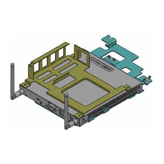
- Page 17 2.3 Hardware Installation 2.3.1 HDD Installation (1) To assembly a HDD module, secure HDD to HDD bracket with 2 screws. (2) Install a HDD module into DS‐565, then secure it with a screw. SATA connector Screw 1 HDD bracket Screw 2 Figure. 14 HDD Installation Top cover HDD Module FAN Module Installed direction Bottom cover Figure. 15 System Installation 17 ...
- Page 18 2.3.2 Memory Installation (1) Be easy to install/ remove memory on bottom cover. (2) Remove memory cover and replace memory inside. (3) Install the memory cover, then secure with screw. Screw Memory cover Figure. 16 Memory Installation 18 ...
-
Page 19: Chapter 3 Bios Settings
Chapter 3 BIOS Settings This chapter introduces how to set BIOS configuration data. 3.1 BIOS Introduction AMIBIOS has been integrated into many motherboards for over two decades. With the AMIBIOS Setup program, you can modify BIOS settings and control various system features. This chapter describes the basic navigation of the DS‐565 series BIOS setup screens. AMIBIOS’s ROM has a built‐in setup program that allows users to modify the basic system configuration. This information is stored in battery‐backed CMOS so it retains the setup information when the power is turned off. 3.2 Main Setup When you first enter the BIOS Setup Utility, you will enter the Main setup screen. You can always return to the Main setup screen by selecting the Main tab. The Main BIOS setup screen has two main frames. The left frame displays all the options that can be configured. Options in blue can be configured, and grayed‐out options cannot be configured instead. The right frame displays the key legend. The key legend in the top is an area reserved for a text message. When an option is selected in the left frame, it is highlighted in white. Often a text message will accompany it. 3.2.1 System Time/ System Date Use this option to change the system time and date. Highlight System Time or System Date using the <Arrow> keys. Enter new values through the keyboard. Press the <Tab> key or the <Arrow> keys to move between fields. The date must be entered in MM/DD/YY format. The time must be entered in HH:MM:SS format. Figure. 17 Main Setup Screen 19 ... - Page 20 3.2.2 Advanced BIOS Features Setup Select the Advanced tab from the DS‐565 setup screen to enter the Advanced BIOS Setup screen. You can select any of the items in the left frame of the screen, such as CPU configuration, to go to the sub menu for that item. You can display an Advanced BIOS Setup option by highlighting it using the <Arrow> keys. All Advanced BIOS Setup options are described in this section. The Advanced BIOS Setup screens are shown below. The sub menus are described on the following pages. Figure. 18 Advanced BIOS Features Setup Screen This section allows you to control hardware monitoring and power ACPI Settings: management CPU Configuration: Hyper‐threading: Enabled for Windows XP and Linux (OS optimized for Hyper‐Threading Technology) and Disabled for other OS (OS not optimized for Hyper‐Threading Technology). When disabled, only one thread per enabled‐core is enabled. Active Processor Cores: Number of cores to be enabled in each processor package. Limit CPUID Maximum: Disabled for Windows XP. Execute Disable Bit: It can prevent certain classes of malicious buffer overflow attacks when combined with a supporting OS (Windows Server 2003 Sp1, Windows XP SP2, SuSE Linux 9.2 RedHat Enterprise 3 Update 3.). Intel Virtualization Technology: When enabled, a VMM can utilize the additional hardware capabilities provided by Vander pool Technology. Hardware Prefetcher: To turn on/off the Mid Level Cache (L2) streamer prefetcher. Adjacent Cache Line Prefetch: To turn on/off prefetching of adjacent cache lines 20 ...
- Page 21 Figure. 19 CPU Setting page SATA Configuration: This section allows you to set up SATA devices configuration. SATA Controller(s): Enable or disable SATA Device. SATA Mode Selection: Determines how SATA controller(s) operate. The choice: IDE, AHCI, RAID Figure. 20 SATA Setting page Configuration Management Engine Technology Parameters. PCH-FW Configuration: Configuration: Configuration Active Management Technology parameters. Intel AMT: Enable/Disable Intel(R) Active Management Technology BIOS Extension. 21 ...
- Page 22 Note: iAMT H/W is always enabled. This option just controls the BIOS extension. If enabled, this requires additional firmware in the SPI device. BIOS Hotkey Pressed: OEMFLag Bit 1: Enable/Disable BIOS hotkey press. MEBx Selection Screen: OEMFLag Bit 2: Enable/Disable MEBx selection screen. Hide Un‐Configure ME Confirmation: OEMFLag Bit 6: Hide Un‐Configure ME without password Confirmation Prompt. MEBx Debug Message Output: OEMFLag Bit 14: Enable MEBx debug message Output. Un‐Configure ME: OEMFLag Bit 15: Un‐Configure ME without password. Amt Wait Timer: Set timer to wait before sending ASF_GET_BOOT_OPTIONS. ASF: Enable/Disable Alert Specification Format Activate Remote Assistance Process: Trigger CIRA boot. USB Configure: Enable/Disable USB Configure function. PET Progress: User can Enable/Disable PET Events progress to receive PET events or not. WatchDog: Enable/Disable WatchDog Timer. Figure. 21 AMT Configuration setting USB Configuration Parameters. USB Configuration: Legacy USB Support: Enable Legacy USB support. AUTO option disables legacy support if no USB devices are connected. DISABLE option will keep USB devices available only for EFI applications EHCI Hand‐off: This is a workaround for 0Ses without EHCI hand‐off support. The EHCI ownership change should be claimed by EHCI driver. USB transfer time‐out: The time‐out value for Control, Bulk, and Interrupt transfers. The choice: 1 sec, 5 sec, 10 sec, 20 sec Device reset time‐out: USB mass storage device Start Unit Command time‐out. The choice: 10 sec, 20 sec, 30 sec, 40 sec Device power‐up delay: USB mass storage device Start Unit Command time‐out. 22 ...
- Page 23 Figure. 22 USB Configuration setting Serial Port 0 Configuration: Set Parameters of Serial port 0 (COM) Figure. 23 Serial Port 0 Configuration setting CPU PPM Configuration Parameters CPU PPM Configuration: EIST: Enable/Disable Intel SpeedStep Turbo Mode: Turbo Mode CPU C3 Report: Enable/Disable CPU C3(ACPI C2) report to OS 23 ...
- Page 24 Figure. 24 CPU PPM Configuration setting 3.2.3 Chipset BIOS Feature Setup Select the Chipset tab from the DS‐565 setup screen to enter the Chipset BIOS Setup screen. Users can select any item in the left frame of the screen, such as PCH‐IO Configuration and System Agent Configuration. 3.2.4 Security BIOS Feature Setup Select the BOOT tab from the setup screen to enter the Security BIOS Setup screen. Administrator Password: Set up Administrator Password. When set, limits access to BIOS Setup. User Password: Set User Password. When set, limits machine boot and access to BIOS Setup. 24 ...
- Page 25 Figure. 25 Security BIOS 3.2.5 Save & Exit BIOS Feature Setup Select the BOOT tab from the setup screen to enter the save BIOS Setup screen. Save Changes and Exit: Exit system setup after saving the changes. Discard Changes and Exit: Exit system setup without saving any changes. Save Changes and Reset: Reset the system after saving the changes. Discard Changes and Reset: Reset system setup without saving any changes. Save Changes: Save Changes done so far to any of the setup options. Discard Changes: Discard Changes done so far to any of the setup options. Restore Defaults: Restore/Load Defaults values for all the setup options. Save as User Defaults: Save the changes done so far as User Defaults. Restore User Defaults: Restore the User Defaults to all the setup options. Figure. 26 Save & Exit BIOS Feature Setup 25 ...
- Page 26 26 ...
Need help?
Do you have a question about the DS-563SQ-S6A1E and is the answer not in the manual?
Questions and answers