
Related Manuals for Joy Sport CT-Unicum


Summary of Contents for Joy Sport CT-Unicum
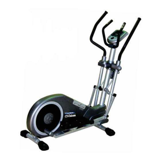
- Page 1 J o y S p o r t The Choice Of The Experts Fitness-Import Timmermannsweg 46 5813 AP Ysselsteyn (LB) info@joysport.nl www.joysport.nl...
-
Page 2: Warning Decal Placement
INHOUDSOPGAVE Veiligheidsvoorschrift en Joy Sport Importeur………………… ..………………………………1‐2 Belangrijke veiligheids…………………………………………..............3 Bediening van de VST‐ ADJUSTOR……………………................4 hoofdbestanddelen………………………………………………………………………………....5‐6 Hardware Kit………………………………………………….................7 Montageinstruktie……………………………………..…………………………………………………..9‐18 Computerhandleiding…………………………………………………..........19‐26 Afstellig Rollen………………………………………………………………………………………………... 27 Overzicht………………………………………………….………..............…28 Onderdelenlijst……………………………………………….………….……………………………………29‐30 Transport en opslag……………….……………………………………………...…........31 WARNING DECAL PLACEMENT JOYSPORT www.joysport.nl... - Page 3 Deze garantie geldt gedurende 24 maanden voor elke fabricagefout aan uw JOY SPORT product die door een JOY SPORT dealer werd verkocht. Wanneer u garantie claimt bied JOY SPORT de mogelijkheid om naar eigen goeddunken het defecte apparaat of het betreffende onderdeel te herstellen of te vervangen.
- Page 4 Belangrijk, veiligheidsvoorschrift. Waarschuwing: Om risico of letsel van de gebruiker te voorkomen, lees deze instructie zorgvuldig. De eigenaar is er verantwoordelijk voor dat gebruikers kennis kunnen nemen van deze instructie. De trainer dient alleen gebruikt te worden als beschreven in de handleiding. Zorg dat de ventilatieopeningen vrij blijven van stof etc. Stop geen vreemde voorwerpen in de openingen. Plaats de trainer op een vlakke ondergrond, om vloer of tapijt te sparen kunt u er en mat onderleggen. Gebruik het apparaat niet buiten, want vocht en stof kunnen een nadelige invloed hebben op de werking en de levensduur van het apparaat De aanbevolen ruimte is 50 cm aan de zijkanten en 1 meter aan de achterkant om veilige werking mogelijk te maken en vrije ruimte om het apparaat te hebben. Maximaal gewicht gebruiker bedraagt 150 kg. Draag geschikte kleding tijdens gebruik en voorkom dat kledingstukken tussen de bewegende delen komen. De gegevens van de computer zijn geen precisie metingen maar enkel een indicatie voor de status van het moment en een hulpmiddel voor de trainingen. ...
- Page 5 Bediening weerstandsknop Weerstandsknop heeft 5 posities om weerstand in te stellen posities om zwaarte in te stellen Weerstandsknop heft 5 Reikwijdte (Instellen van de lengtepas ) inch /cm 21 Inch 17 Inch 18 Inch 19 Inch 20 Inch 53 CM 43 CM 45 CM 48 CM...
- Page 6 Onderdelen Joy Sport CT-Unicum Hoofdframe Staander Computer verbindingsbuis voetsteun buis(L) Pedaal(L) voetsteun buis(R) Pedaal(R) voorsteun Zwaai Arm handgreep (L) achtersteun Zwaai Arm Handgreepbar (R) Handgreep tweede voetsteun buis (L) JOYSPORT www.joysport.nl...
- Page 7 Onderdelen Joy Sport CT-Unicum weerstandsknop Tweede voetsteunbuis (R) voorafdekking staander bovenafdekking (L-R) achterafdekking staander onderafdekking ( L & R ) voorafdekking draaiarm achterafdekking draaiarm bovenafdekking buis voetsteun (L) onderafdekking buis voetsteun voetsteunbuisafdekking (L) Voetsteunbuisafdekking (R) Bidonhouder Adapter Hardware Box CT-Unicum...
- Page 8 Onderdelenlijst Joy Sport CT‐Unicum Nummer Onderdeel Aantal Stap nummer Nummer Onderdeel Aantal Stap nummer Nummer Onderdeel Aantal Stap nummer STAP:1 #122 STAP:6 #122 STAP:12 STAP:1 STAP:7 #122 STAP:13 STAP:1 STAP:8 #128 STAP:13 STAP:1 STAP:8 STAP:14 STAP:2 STAP:8 STAP:14 STAP:2 STAP: 8 STAP:14 STAP:2 STAP:9 STAP:15...
- Page 9 Joy Sport CT Unicum JOYSPORT www.joysport.nl...
- Page 10 STAP:1 Voorsteun montage Nummer Onderdeel Aantal 1) Bevestig de voorsteun met transportwielen aan het hoofdframe met 2 bouten (#19) vulringen (#65) moeren (#20). 2) Zet de moeren goed vast en dek ze af met 2 sierafdekkingen (#21). STAP:2 Achtersteun montage Nummer Onderdeel Aantal 1) Om de achtersteun te monteren is het makkelijk het hoofdframe wat te verhogen door er een verpakkingsdeel onder te leggen. 2) Bevestig de achtersteun op het hoofdframe met 2 bouten (#19) vulringen (#65) moeren(#20). 3) Zet de moeren goed vast en dek ze af met de sierafdekkingen (#21). STAP:3 Inch versteller montage Nummer Onderdeel Aantal 1) Leg de voorgemonteerde staander ontdeel (#68)plat op de vloer ( zie foto) bevestig eerst de kabels tussen knop (#116) en voorstaander. 2) Zet de versteller tegen de staander. 3) Zet de versteller handvast met 4 boutjes ( #18). STAP:4 Montage staander op hoofdframe Nummer Onderdeel Aantal 1) Bij deze stap is de hulp van een eventuele tweede persoon aanbevolen. 2) Klik de stekkers in elkaar, en plaats de staander in het hoofdframe, let op dat u de kabel niet knikt. 3) Plaats de 6 schroeven (#18) en draai ze losjes aan. Attentie: zet de schroeven (#18)in deze fase niet vast. JOYSPORT www.joysport.nl...
- Page 11 JOYSPORT www.joysport.nl...
- Page 12 STAP:5 Montage beschermkapjes Nummer Onderdeel Aantal #122 1) Monteer de onderafdekking (#104,#105) boven/onder om buis (#75). 2) Zet de afdekking vast met bout (#30), en schroef ze samen met 2 zelftappers.(#122). STAP:6 Pedaal Montage (1) Nummer Onderdeel Aantal 1) Let op! De linker en rechter kant worden aangegeven met een sticker (L/R). #122 2) Zet het vliegwiel met het asje omhoog en schuif de pedaalbuis over het asje. 3) Gebruik vulring (#17), moer (#12), draai de moer (#12) vast op de as. 4) Monteer dan de afdekkapjes (#108/#109 )met schroeven (#122). STAP:7 Pedaal montage ( 2 ) Nummer Onderdeel Aantal 1) Schuif de buizen in elkaar (#86) in buis (#69/70). 2) Verbind deze met de schroeven (#18). Atentie: losjes aandraaien, nog niet vastzetten. STAP:8 Lange as montage Nummer Onderdeel Aantal Monteer de voorgemonteerde lagers aan het daarvoor bestemde onderdeel (#100), Let hierbij op het embleem "UP " aan de kant van de grote ring & en de kleine ring, Gebruik de grote ring op de plaats "outside " Zoals in het plaatje aangegeven verbind het met de kleine as op de plaat (#101), met ringen (#39), bouten (#18) Zet deze goed vast (#46) aan de grote ring. JOYSPORT www.joysport.nl...
- Page 13 JOYSPORT www.joysport.nl...
- Page 14 STAP:9 D‐as voor bevestiging verbindingsstangen Nummer Onderdeel Aantal 1) Plaats de d‐as(#63) door de smalle ring van de verbindingsstang (#100), en door de ruimte in de verstelknop (#116) en door de smalle ring van de andere verbindingsstang. 2) Opmerking! Als de d‐as er moeilijk in gaat draai dan de schroeven van stap 3 iets losser zodat er wat meer speling is en zodoende de montage eenvoudiger gaat 3) Plaats de vulring (#39) en bouten (#18) aan beide zijden van d‐as, met de twee 10mm inbussleutels beide bouten gelijktijdig aandraaien, zie foto en draai de bouten uit stap 3 weer aan, als u deze losser gedraaid heeft. STAP:10 Tweede pedaalbuis montage Nummer Onderdeel Aantal 1) Plaats de grote PU rol aan de tweede pedaalbuis midden op de ALUM. rail (#113) op de pedaalbuis (#75). 2) Plaats de"U" klem over de korte zwaaiarm (#98) 3) Schuif de asjes (#14) door beide delen en plaats de vulringen en moeren op beide zijden van de as en zet deze goed vast. 4) Monteer de beschermkapjes. STAP:11 Montage zwaaiarm boven Nummer Onderdeel Aantal 1) Plaats de boven zwaaiarm (#72&#73), in de buisdelen (#69 F). 2) Draai de boutgaten voor de gaten in de buis, (#72 & #69) en (#73 F) met bout (#18) veerring #A, en vulring( #65) en zet ze goed vast. STAP:12 Draaipuntafdekking. Nummer Onderdeel Aantal #122 1) De afdekkingen bestaan uit een voor en achterzijde.
- Page 15 JOYSPORT www.joysport.nl...
- Page 16 STAP:13 Montage middenafdekking en bidonhouder Nummer PARTS LIST QUANTITY #122 1) Breng verstelknop in de laagste stand, laat genoeg ruimte vrij #128 om de middenafdekking en bidonhouder te plaatsen. 2) Verbind bidonhouder (#127) en achterafdekking (#125) met 4 schroeven (#128) voor ronde staande buis en/of twee boutjes (#30). 2) Zet bidonhouder en afdekking goed vast (#126) in het midden van de staande buizen zet deze met 4 schroeven vast (#122). STAP:14 Montage handgrepen Nummer Onderdeel Aantal 1) Plaats de handgreep (#71) met de boutjes (#6) in de greephouder aan de staande buis en zet ze vast met M10 inbussleutel. 2) Schuif de sensorkabels door de gaten onder de handgreep in de staande buis omhoog (#71). 3) Laat ze aan bovenzijde uitsteken. 4) Zet de afdekking vast met schroeven ( #61). Attentie! De afdekking met een moer aan de binnenzijde is de #134 onderkant (#97) voor en afdekking (#134) ronde buis STAP:15 Computer plaatsen Nummer Onderdeel Aantal 1) Verbind de kabels van de computer (#43) & en de kabels uit de staander samen 2) Attentie! Check & plug kabels, zelfde kleur samenvoegen, zorg dat alle kabels goed in elkaar geklikt worden. 3) Plaats de computer op de topplaat van de staander en zet vast met boutjes (E).
- Page 17 JOYSPORT www.joysport.nl...
- Page 18 STAP:17 Rolafstelling en eindbevestiging Nummer Onderdeel Aantal 1) Zet de rollers tussen de alu rails. 2) Draai de rollers in het midden van de baan. 3) Als het niet helemaal lukt beweeg de staander (#72I) zachtjes van links naar rechts, de rollen zullen nu makkelijker het midden opzoeken. ,zet alle schroeven vast (#18) ook 4) Na het positioneren van de rollen die eerst los vast gezet zijn STAP 3, 4 and STAP 7. Tot slot met sleutel alles goed vastzetten (# 18). STAP:18 Instellen van kabel weerstandsknop Nummer Onderdeel Aantal 1) Trek eerst de knop op en draai de weerstand naar laag of hoog. 2) Om in te stellen kunt u de knop omhoog of omlaag stellen naar een stand die gewenst is. Er zijn vijf standen. 3) Op eind vastzetten met sleutel STAP:19 ADAPTER Nummer Onderdeel Aantal 1) Plaats adapter (#92) in geaard stopcontact. 2) Plaats de connector in het achtergedeelte van het apparaat. JOYSPORT www.joysport.nl...
- Page 19 JOYSPORT www.joysport.nl...
- Page 20 Computer Handleiding Ⅰ. Inschakelen Stroom in: Sluit de stekker aan op een geaard stopcontact. Vervolgens de schakelaar naast de kabelingang op On zetten. Een luide piep klinkt, en het display licht op (Fig. 1) en gebruikersselectie verschijnt binnen enkele seconden. (Fig. 2) Uitschakelen: De console zal zichzelf uitschakelen na 4 minuten geen signaal te hebben ontvangen.
- Page 21 4. Instelling lengte In display licht “H.t” op rechts boven in Druk om uw lengte in te stellen Druk om uw lengte te bevestigen. ENTER 5. Instelling gewicht. Display geeft “W.t” aan rechts boven. Druk om uw gewicht in te stellen ...
- Page 22 6. PERSOONLIJKE PROGRAMMA INSTELLINGEN. Voor elk in te stellen programma,kunt u de waarden naar wens wijzigen. Als u drukt.. ENTER Kunt u LEVEL wijzigen Druk om instelling te wijzigen en druk om LEVEL te bevestigen ENTER Wijziging van tijd. Druk om te wijzigen en druk om TIME te bevestigen.
- Page 23 Druk bij H.R.C. (55%, 75%, 90%, Tag)… ENTER U kunt nu een hartslag programma selecteren, Druk om een programma te selecteren en druk om te bevestigen. ENTER Wijzigen tijd Druk naar gewenste waarde en druk om tijd te bevestigen. ENTER ...
- Page 24 Ⅲ. Vooringestelde Programma Diagrammen PROGRAM(P1-P12) ● P1 ● P2 ● P3 ● P4 ● P5 ● P6 ● P7 ● P8 ● P9 ● P10 ● P11 ● P12 HRC(55%, 75%, 90%, Tag) ●HRC(55%) ●HRC(75%) ●HRC(90%) ●HRC(Tag) JOYSPORT www.joysport.nl...
- Page 25 Fitness Evaluatie gegevens 1. Body Fat Instelling druk om te starten (Leg uw handen op de detectoren om uw hartslag te meten.) Als geen BODY FAT hartslag gemeten wordt binnen 10 minuten verschijnt error in het display. Als de hartslag gemeten wordt, body fat evaluatie begint en geeft aan na 25 sec.
- Page 26 2. Hartslag Evaluatie Deze geeft aan hoe uw hart functioneerd. Het geeft aan hoe uw hart hersteld na een inspannende training. NOTE! That the heart rate displayed may be inaccurate and used for reference om de test te beginnen (Plaats uw handen op de detectoren). Als de hartslag gemeten wordt Druk RECOVERY zal de meting beginnen en na 60 seconden uitslag geven.
- Page 27 6. BODY FAT Gebruik deze om programma te starten. 7. RECOVERY Gebruik deze knop voor hartslag evaluatie Specifikaties Item Display Display Range Setting Range Default Memory MALE/ FEM SEX(性别) 10 - 100 AGE(年龄) 20 - 330(Lb) WEIGHT(METRIC 公制)体重 10 - 150(KG) 36 - 84(INCH) HEIGHT(身高) 90 –...
- Page 28 Rolverstelling Nadat het apparaat geheel gemonteerd is, Kan het zijn dat een van de rollen te dicht tegen de rail zit. U kunt de rollen op de volgende manier bijstellen. Photo 1 STAP1 Als getoond in foto 1 en tekening 1,verwijder twee schroeven en neem rolafdekking weg. Als het linker en rechterpedaal verschillend zijn, Is ook de afdekking anders. Er zijn 3 moeren aangegeven met ➀、➁、➂ voor iedere moer. STAP2 Photo 2 Als te zien in de tekening en foto 2, gebruik ...
- Page 29 JOYSPORT www.joysport.nl...
- Page 30 Joy Sport CT-Unicum Onderdelen Overzicht onderdeel nr omschrijving Unicum onderdeel nr. omschrijving Unicum eindkap handvat ☆ eindkap ☆ ☆ ☆ handvat bekleding middenafdekking links T-steun ☆ middenafdekking rechts ☆ ☆ ☆ polsslagsensor zijafdekking links eindkap ☆ zijafdekking rechts ☆ schroef ☆...
- Page 31 Joy Sport CT-Unicum Onderdelen Overzicht onderdeel nr omschrijving Unicum onderdeel nr. omschrijving Unicum bout ☆ linker rol houder ☆ lager rechterrolhouder ◎ alu rail ☆ onderbalk links ☆ bout onderbalk rechts AD basis ☆ Vliegwiel steun bediening ☆ bevestiging stuur ☆...
- Page 32 JOYSPORT www.joysport.nl...
- Page 33 J o y S p o r t The Choice Of The Experts Fitness-Import Timmermannsweg 46 5813 AP Ysselsteyn (LB) info@joysport.nl www.joysport.nl...
-
Page 34: Table Of Contents
TABLE OF CONTENTS WARNING DECAL PLACEMENT………………………………………………………………………………………….1‐2 IMPORTANT SAFTY………………………………………………………………………………………………………….. .…3 VST (VARIABLE STRIDE LENGTH) SYSTEM……………………………….……………………………………… ….4 HOW TO OPERATE THE VST‐ ADJUSTOR…………………….................5 HARDWARE PACKAGE CONTENTS……………………………………………………………………………………. 6‐7 HARWARD KIT………………………………………………………..………………………………………………… …… 8 ASSEMBLY INSTRUCTIONS………………………………………..………………………………………. …………… 9‐18 CONSOLEMANUAL……………………………………………………................19‐26 ROLLER ADJUSTMENT………………………………………………………………………………………………………… 27 EXPLODED VIEW………………………………………………….……….............. 28 PARTS LIST…………………………………………………….………….………………………………………………… .. 29‐30 TRANSPORT AND STORAGE……………….……………………………………………...………………………….…… ..31 WARNING DECAL PLACEMENT JOYSPORT www.joysport.nl... - Page 35 Dear customer, We want to thank you for having chosen a JOY SPORT product, and wish you a lot of fun and success during training with your JOY SPORT exercisers. Please note and follow the enclosed safety and assembly instructions carefully.
- Page 36 IMPORTANT SAFETY INSTRUCTIONS IMPORTANT ELLIPTICAL EXERCISER WARNINGS AND CAUTIONS READ AND UNDERSTAND THESE WARNINGS AND CAUTIONS WARNING: In order to reduce the risk of injury to any and all persons, READ and UNDERSTAND the following important PRECATIONS and information before operating or allowing others to operate the elliptical exerciser. The owner has the responsibility of ensuring that all users of the elliptical exerciser are adequately informed of all warnings and precautions This elliptical exerciser should not be used by, on, or near children, invalids, or disabled persons. This elliptical exerciser must only be used as described in the manual. Attachments that are not recommended by the manufacturer must not be used. Never operate the elliptical exerciser with the air openings blocked, Keep the air openings free of lint, hair and the like. Never operate the elliptical exerciser on a soft surface such as a bed or a couch where the air openings may be blocked. Never drop or insert any object into any opening. Place the elliptical exerciser n a level surface. To protect the floor and carpet from damage, place a mat under the elliptical exerciser. DO NOT uses or store the elliptical exerciser outdoors, in a garage or covered patio, keep the elliptical exerciser away from moisture and dust. The elliptical exerciser should be used indoors. Heat, moisture and dirt can adversely affect the operation of this elliptical exerciser. ...
-
Page 37: Vst (Variable Stride Length) System
(Variable Stride Length) System At GO-elliptical, it is our mission to build the most versatile yet affordable elliptical cross trainers without sacrificing utility/performance and comfort for the whole family. After years of research and development, we have perfected an patented adjustable stride length technology ergonomically designed to achieve a level of fit with biomechanics without keeping on raising the pedal incline degrees–... -
Page 38: How To Operate The Vst- Adjustor
HOW TO OPERATE THE ADJUSTOR ADJUSTOR comes with five (5) adjustable locations for different ranges of stride length VST Range VST Range (Variable Adjustable Stride Length ) inch / mm (Variable Adjustable Stride Length ) inch /cm CT-Unicum 17-21 inch 43-53 cm Simply release the knob going down (Top hole is the smallest range) to adjust stride length. To make further adjustments, first pull up the knob then move it down to the new desired location. Finally, set the knob/pin to the new location by locking up the knob. There are two places that will display the stride length selection you just made: ... - Page 39 HARDWARE PACKAGE/PARTS/TOOLS Joy Sport CT-Unicum NOTE: USE THE TOOLS ONLY FOR THIS "VST" ELLIPTICAL Base Frame Up right tube Console Long connecting bar Pedal support tube(L) Pedal(L) Pedal support tube(R) Pedal(R) Front stabilizer Swing Arm Handle bar (L) Rear stabilizer Swing Arm Handle bar (R)
- Page 40 HARDWARE PACKAGE/PARTS/TOOLS Joy Sport CT-Unicum NOTE: USE THE TOOLS ONLY FOR THIS "VST" ELLIPTICAL Adjustor Pedal support tube Second (R) Front cover for upright tube step foot cover-top (L & R ) Rear cover for upright tube step foot cover-Bottom ( L & R )
- Page 41 Hardware kit contents Joy Sport CT‐Unicum KEY NO PARTS LIST QUANTITY STEP NO. KEY NO PARTS LIST QUANTITY STEP NO. KEY NO PARTS LIST QUANTITY STEP NO. STEP:1 #122 STEP:6 #122 STEP:12 STEP:1 STEP:7 #122 STEP:13 STEP:1 STEP:8 #128 STEP:13 STEP:1 STEP:8 STEP:14 STEP:2 STEP:8 STEP:14 STEP:2...
- Page 42 STEP:1 FRONT SUPPORT ( Front Stabilizer) ASSY. PARTS LIST QUANTITY As photo shown 1) in order to facilitate assembly, use one of the larger styroform set under the Frame ( as photo shown) 2) Attach the front support with transportation wheels to the frame with two bolts (#19) washers (#65) nuts (#20) 3) locking sleeves with tool and cover the nut with two caps (#21) STEP:2 REAR SUPPORT ( Rear Stabilizer) ASSY. PARTS LIST QUANTITY As photo shown 1) In order to facilitate assembly, use one of the larger styroform set under the Frame ( as photo shown) 2) Attach the rear support to the frame with two bolts (#19) washers (#65) nuts (#20) 3) locking sleeves with tool and cover the nut with two caps (#21) STEP:3 STRIDE LENGTH ADJUSTOR ASSY. PARTS LIST QUANTITY As photo shown 1) place the pre‐assembled upright tube (#68) flat on the floor ( as photo shown) 1‐1) First, connect the cables between upright tube and the adjustor (#116) 1‐2)pull another section cables of upright tube facilitate enter to the upright tube 2) the adjustor with semi‐circular piece with the tube and align the bolt. Note! the adjustor can not hold against the upper and lower 3) hand tightern the adjustor with four bolts ( #18) to the upright tube NOTE! DO NOT TOTALLY TIGHTEN ALL FOUR BOLTS (#18). KEEP THE ADJUSTOR IS MOVEABLE FROM SIDE TO SIDE AT THIS POINT. STEP:4 UPRIGHT TUBE ASSY. TO THE FRAME PARTS LIST QUANTITY As photo shown 1) place upright tube on top of a chair ( or by a second person to assist holding) close to the main frame be facilitated to connect the cables. 2) check the direction of upright tube before connect the Top/Bottom pre‐assembled cables as photo shown.
- Page 43 JOYSPORT www.joysport.nl...
- Page 44 STEP:5 STEP FOOT COVEER ASSY. PARTS LIST QUANTITY #122 As photo shown 1) Set the step foot coves (#104,#105) Top/Bottom with the pedal support tube (#75) 2) locking up the covers with the screw (#30), then fix the covers with 2 self‐tapping screws(#122). STEP:6 PEDAL SUPPORT TUBE ASSY ( 1 ) PARTS LIST QUANTITY As photo shown 1) Frist, distinguish between the left/right pedal support tube (note: check pedal support tube with left/right label) #122 2) move pulley to the upper position, insert rear part of both pedal support tube (#75) to the axle on pulley. 3) add washers (#17), nut (#12), locking up the nut (#12) with axle 4) then tighten up the rear pedal support tube coveers (#108/#109) with screws (#122) The distinction between pedal support tube covers left/right NOTE! STEP:7 PEDAL SUPPORT TUBE ASSY ( 2 ) PARTS LIST QUANTITY As photo shown 1) insert both of connecting tubes (#86) with front part of step tubes to the swivel tubes (#69) 2) Connecting both (#86) tube with (#69 & #70) with screws (#18). NOTE: Use finger lightly tighten the (#18) screws at this STEP, DO NOT TIGHTEN TOTALLY STEP:8 LONG CONNECTIING BAR ASSY PARTS LIST QUANTITY As photo shown Pre‐asssebled ball bearing on both end of long connecting bars (#100), check the sign of "UP " one side with big ring & one with samll ring, use the big ring side check the "outside " direction as figure shown connecting it with the...
- Page 45 JOYSPORT www.joysport.nl...
- Page 46 STEP:9 D‐AXLE ASSY OF ADJUSTOR CONNECTION SHAFT PARTS LIST QUANTITY As photo shown 1) Use a pair of working gloves with item to do the assembly, set the D‐Axle (#63) from one of the small ring on top of Long connecting bar (#100), use D‐Axle set thru top tube of adjustor (#116) then set it thru the other small ring on top of the other Long connecting bar. 2) Note! If D‐Axle set thru top with any difficulty, release screws in STEP:3 ( stride length adjustor assy), so adjustor will get more space tolerance to enable the D‐Axle (#63) easy to assemble. 3) Add washer (#39) and screws (#18) to both end of D‐Axle, with two M10 Allen Key as photo shown, tighten up both screws (#18) at the same time then locking up all screws (#18) with the adjustor assy. that was finger tightened in the STEP:3 STEP:10 SECOND PEDAL SUPPORT TUBE ASSY PARTS LIST QUANTITY As photo shown 1) set the large PU roller pre‐assembled with the second pedal support tube to the center of ALUM. rail (#113) pre‐assembled on the pedal support tube (#75) 2) fit the front "U" bracket with the pre‐assembled short square swing arms (#98) 3) as photo shown insert both small axle (#14) thru both parts ( due to the samll axle is in spec. if with difficulty to set it thru both parts, add nut (#12) to outside of small axle with the hex wrench to back & forth rotate the axle, it will be easy to put thru 4) set washer (#11) & nut (#12) to both side of small axle as photo shown with two tools to locking up totally. Note! Due to the second pedal support tube is a moving part MAKE SURE! to release both nut (#12) half to one cycle then cover the end cap (#5) and make sure the pedal support tube be able to move up/down freely. STEP:11 UPPER SWING ARM HANDLEBAR PARTS LIST QUANTITY As photo shown 1) set the swing arm handlebar R/L (#72&#73), insert to both swivel tubes (#69 F). 2) turn and match the handlebars with the aligned holes, secure the parts (#72 & #69) also (#73 F) with screw (#18) and special spring washer #A, then flat washer( #65) tighten up both totally.
- Page 47 JOYSPORT www.joysport.nl...
- Page 48 STEP:13 CENTER COVER & BOTTLE HOLDER ASSY PARTS LIST QUANTITY #122 As photo shown 1) Pull down the knob of adjustor to the lowest position, leave enough space #128 to install the center cover & bottle holder. 2)locking bottle holder(#127) and rear cover (#125) with four screws (#128) for round of upright tube and or two screws (#30) for square of upright tube ( T100) NOTE: #30 IS FOR THE 2) Secure the bottle holder and fron cover (#126) to the center of upright SQUARE UPRIGHT TUBE tube and locking with four screws (#122) STEP:14 FIXED HANDLEBAR ASSY PARTS LIST QUANTITY As photo shown 1) Fit the fixed handlebar (#71) with the screws (#6) and thru the bracket hold of upright tube with M10 Allen Key, 2) Set both EKG grip cables thru the small holes under the fix handlebar (#71) on the upright tube. 3) Pick up the cables from top of the upright tube. #134 4) Secure the fix handlebar covers with screw ( #61) Note! the cover with a nut inside of post is the bottom cover (#97)‐ for and the bottom cover (#134)‐IS FOR T100 ROUND TUBE SQUARE TUBE STEP:15 CONSOLE ASSEMBLY PARTS LIST QUANTITY As photo shown 1) connect cables comes out from console (#43) & cables from the upright tube together.
- Page 49 JOYSPORT www.joysport.nl...
- Page 50 ROLLER ALIGNMENT AND STEP:17 PARTS LIST QUANTITY UPRIGHT TUBE FINAL SECURE As photo show 1) Set Two of the Roller Alignment Bar to each of the roller (Orange stopper on the Alignment bar towards the Rail end) on the Alum. Rail. 2) Place both side Rollers to the center of the Alignment Bar. 3) If the Roller not be able to set right in the center to the Alum. Rail, simply move the handlebar (#72I) slightly from side to side, roller will set in the center of Alignment bar with ease As photo shown : After set both roller in place, secure all screws (#18) 4) originally finger lightly tightened in STEP 3, 4 and STEP 7. Finally with the tool tighten all screws (# 18) firmly. 5) pull out the Alignment Bar from both Alum. Rail beside the rollers Remark: In case user will like to adjust the Roller slightly, it can also follow the Roller adjustment instruction on Pag 27 STEP:18 OPERATE THE ADJSTABLE STRIDE LENGTH‐ ADJUSTOR PARTS LIST QUANTITY As photo shown 1) First, pull the knob out and turn the adjustor base up or down. 2) to adjust the knob simply release it & pull up then more down when the pointer aligned to a scale you desire Note! there are five stride scale 3) Finally, tighten the adjustor base with a hex wrench Note! if the scale shift occurs, you may manually correct the pointer position. STEP:19 POWER ADAPTOR PARTS LIST QUANTITY As photo shown 1) Plug the power cord with power adaptor (#92) into an appropriate outlet IMPORTANT: The elliptical exerciser is not compatible with GFCI‐equipped outlets. 2) The other end of the access hole in the rear of the base frame Note! before plug in, please check the voltage specifications on the label.
- Page 51 JOYSPORT www.joysport.nl...
- Page 52 Joy Sport CT-Unicum Ⅰ. Power Modes Power On: Plug in the power cord with power adaptor into an appropriate outlet. Next, locate and switch “on” the reset/off button on the frame, near the power cord . A loud beep will sound and the display will then light (Fig.
- Page 53 4. .HEIGHT SET UP The console will now flash “H.t” on the upper right-hand corner of the display. Press to select your height. Press to confirm HEIGHT. ENTER 5. .WEIGHT SET UP The console will now flash “W.t” on the upper right-hand corner of the display. ...
- Page 54 6. PERSONALIZE PROGRAM SETTINGS For each preset program, you can further personalize the level of work that you desire. If you pressed on MANUAL… ENTER You can now set up resistance LEVEL Press to adjust setting then press to confirm LEVEL set up. ENTER ...
- Page 55 If you pressed on H.R.C. (55%, 75%, 90%, Tag)… ENTER You can now select a preset target heart rate control program Press to select a program then press to confirm. ENTER You can now set up TIME Press to adjust target then press to confirm TIME set up.
- Page 56 Ⅲ. Preset Program Diagrams PROGRAM(P1-P12) ● P1 ● P2 ● P3 ● P4 ● P5 ● P6 ● P7 ● P8 ● P9 ● P10 ● P11 ● P12 HRC(55%, 75%, 90%, Tag) ●HRC(55%) ●HRC(75%) ●HRC(90%) ●HRC(Tag) JOYSPORT www.joysport.nl...
- Page 57 Fitness Evaluation Features 1. Body Fat Evaluation Press to begin evaluation (Put your for the machine to detect your BODY FAT hand on the EKG grips heart rate.) If no heart rate is detected after 10 minutes have lapsed, “ERROR” will appear on the display. If a heart rate is detected, body fat evaluation will begin and take about 25 seconds.
- Page 58 2. Recovery Heart Rate Evaluation A recovery heart rate is a measurement taken to help determine how well your heart is functioning. It refers to the heart's ability to return itself to a normal rhythm after being elevated during exercise. NOTE! That the heart rate displayed may be inaccurate and used for reference to begin the test.
- Page 59 5. ENTER Use this button to confirm your selection and go on to the next step. 6. BODY FAT Use button to start body fat evaluation test. 7. RECOVERY Use this button to start recovery heart rate evaluation test. Console Feature Specifications Item Display Display Range...
-
Page 60: Roller Adjustment
Joy Sport CT-Unicum Roller Adjustment After the machine is completely assembled, if any of the PU rollers occur too close to the alum rail due to screw size & holes tolerance during the assembly, you may adjust the rollers with the following procedures: Photo 1 STEP1 As shown in Photo 1 and Drawing 1, release, two screws & take off the roller cover. As the left and right pedals are different, you will find two different Roller Assemblies, style A and B, as shown in the drawing. There are three nuts in each style A and B assembly as marked in the drawing ➀、➁、➂ for each nut. STEP2 Photo 2 ... -
Page 61: Exploded View
EXPLODED VIEW A - T300 JOYSPORT www.joysport.nl... -
Page 62: Parts List
Joy Sport CT-Unicum PARTS LIST Key Number Description Unicum Key Number Description Unicum Handlebar end cap ☆ End cap (T-Bar) ☆ ☆ ☆ Handlebar grip Middle cover, LH T-Bar grip ☆ Middle cover, RH ☆ ☆ ☆ Hand pulse grip unit... - Page 63 Joy Sport CT-Unicum PARTS LIST Key Number Description Unicum Key Number Description Unicum Screw ☆ Left roller holder ☆ Bearing Right roller holder ◎ Alum rail ☆ Long metal cross, LH ☆ Screw Long metal cross, RH AD - Base ☆...
- Page 64 JOYSPORT www.joysport.nl...
Need help?
Do you have a question about the CT-Unicum and is the answer not in the manual?
Questions and answers